1998 NISSAN PATROL heating
[x] Cancel search: heatingPage 1 of 128

HEATER &
AIR CONDITIONER
SECTION
HA
CONTENTS
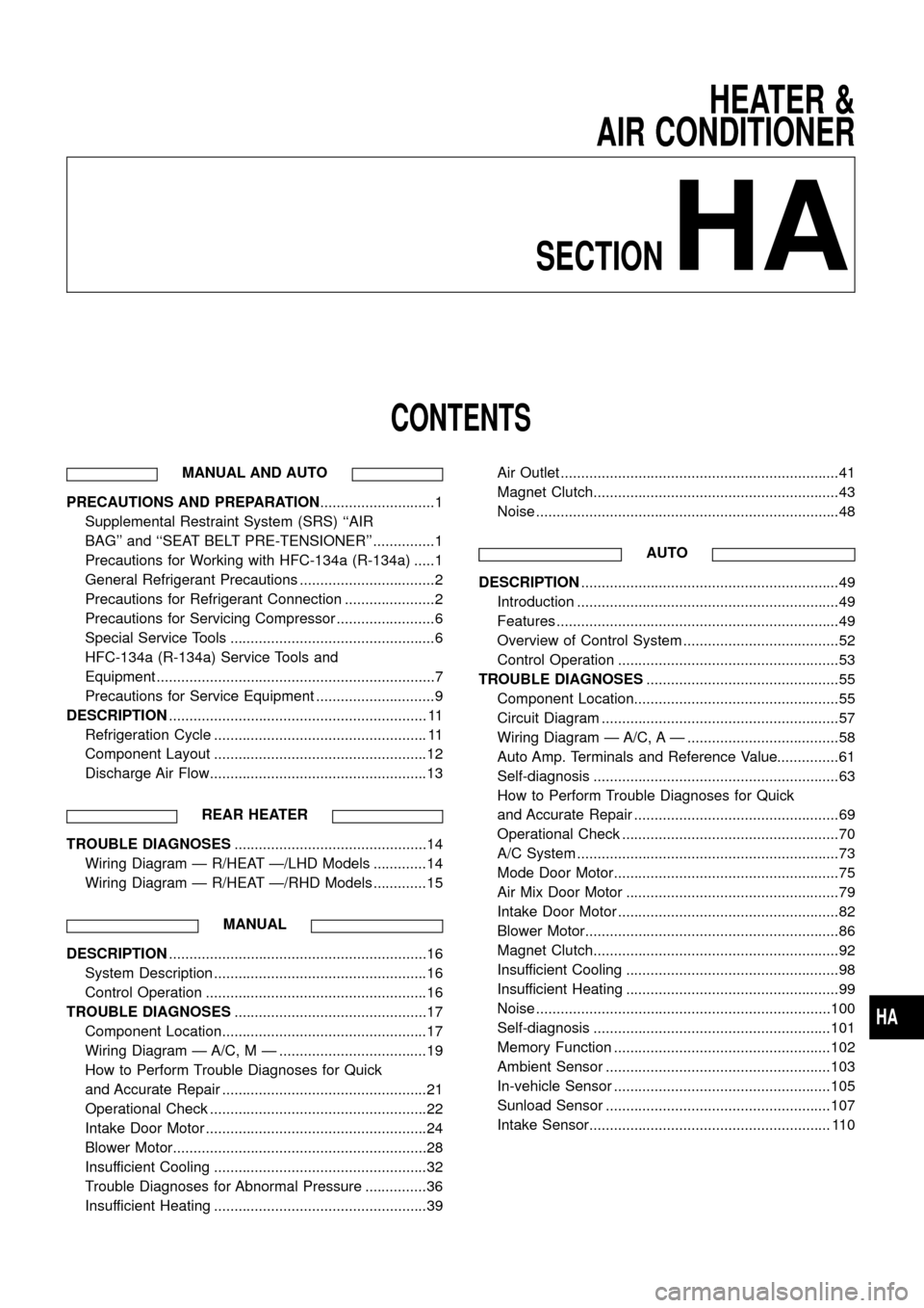
MANUAL AND AUTO
PRECAUTIONS AND PREPARATION............................1
Supplemental Restraint System (SRS) ``AIR
BAG'' and ``SEAT BELT PRE-TENSIONER'' ...............1
Precautions for Working with HFC-134a (R-134a) .....1
General Refrigerant Precautions .................................2
Precautions for Refrigerant Connection ......................2
Precautions for Servicing Compressor ........................6
Special Service Tools ..................................................6
HFC-134a (R-134a) Service Tools and
Equipment ....................................................................7
Precautions for Service Equipment .............................9
DESCRIPTION............................................................... 11
Refrigeration Cycle .................................................... 11
Component Layout ....................................................12
Discharge Air Flow.....................................................13
REAR HEATER
TROUBLE DIAGNOSES...............................................14
Wiring Diagram Ð R/HEAT Ð/LHD Models .............14
Wiring Diagram Ð R/HEAT Ð/RHD Models .............15
MANUAL
DESCRIPTION...............................................................16
System Description ....................................................16
Control Operation ......................................................16
TROUBLE DIAGNOSES...............................................17
Component Location..................................................17
Wiring Diagram Ð A/C, M Ð ....................................19
How to Perform Trouble Diagnoses for Quick
and Accurate Repair ..................................................21
Operational Check .....................................................22
Intake Door Motor ......................................................24
Blower Motor..............................................................28
Insufficient Cooling ....................................................32
Trouble Diagnoses for Abnormal Pressure ...............36
Insufficient Heating ....................................................39Air Outlet ....................................................................41
Magnet Clutch............................................................43
Noise ..........................................................................48
AUTO
DESCRIPTION...............................................................49
Introduction ................................................................49
Features .....................................................................49
Overview of Control System ......................................52
Control Operation ......................................................53
TROUBLE DIAGNOSES...............................................55
Component Location..................................................55
Circuit Diagram ..........................................................57
Wiring Diagram Ð A/C, A Ð .....................................58
Auto Amp. Terminals and Reference Value...............61
Self-diagnosis ............................................................63
How to Perform Trouble Diagnoses for Quick
and Accurate Repair ..................................................69
Operational Check .....................................................70
A/C System ................................................................73
Mode Door Motor.......................................................75
Air Mix Door Motor ....................................................79
Intake Door Motor ......................................................82
Blower Motor..............................................................86
Magnet Clutch............................................................92
Insufficient Cooling ....................................................98
Insufficient Heating ....................................................99
Noise ........................................................................100
Self-diagnosis ..........................................................101
Memory Function .....................................................102
Ambient Sensor .......................................................103
In-vehicle Sensor .....................................................105
Sunload Sensor .......................................................107
Intake Sensor........................................................... 110
HA
Page 23 of 128

How to Perform Trouble Diagnoses for Quick
and Accurate Repair
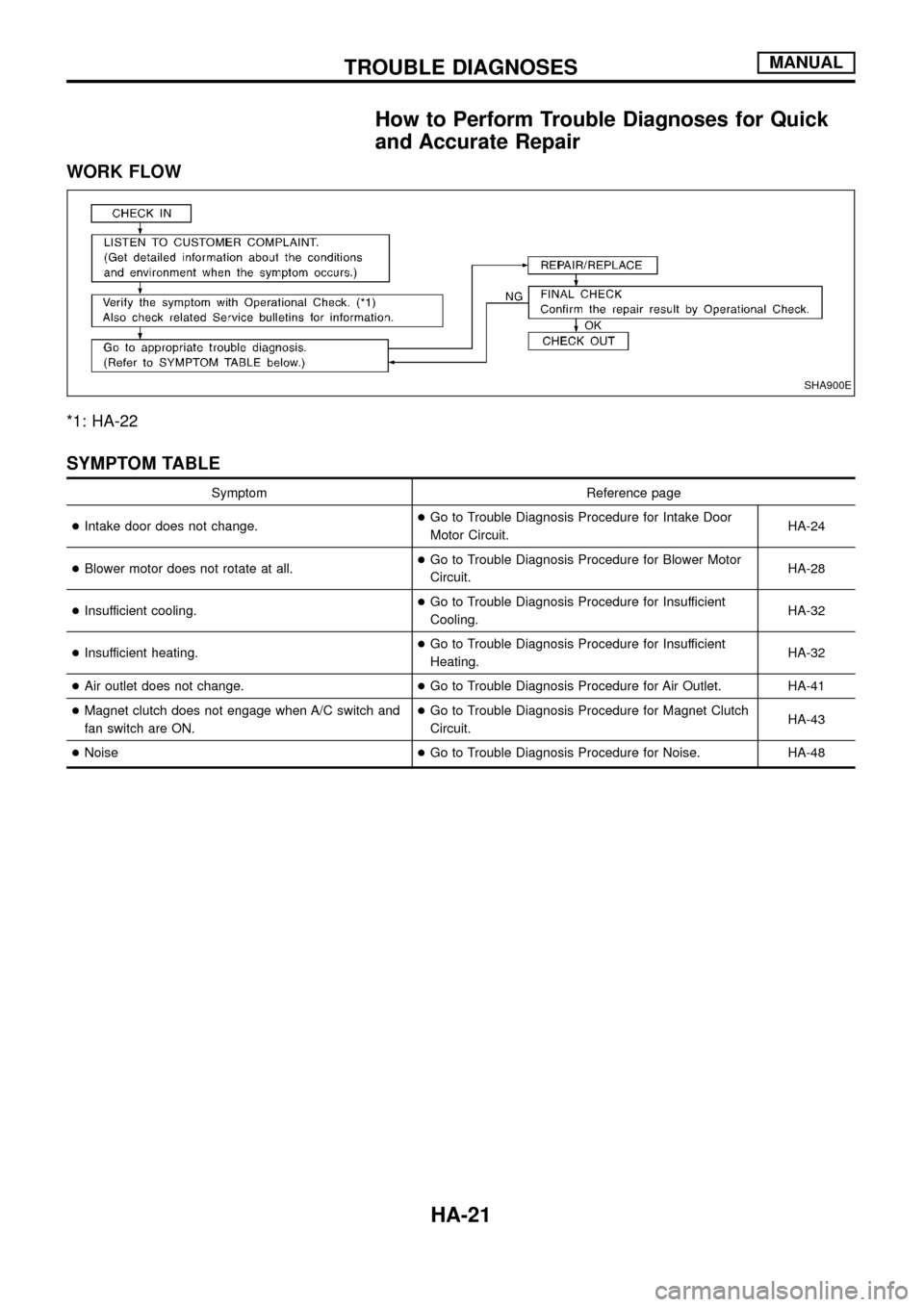
WORK FLOW
*1: HA-22
SYMPTOM TABLE
Symptom Reference page
+Intake door does not change.+Go to Trouble Diagnosis Procedure for Intake Door
Motor Circuit.HA-24
+Blower motor does not rotate at all.+Go to Trouble Diagnosis Procedure for Blower Motor
Circuit.HA-28
+Insufficient cooling.+Go to Trouble Diagnosis Procedure for Insufficient
Cooling.HA-32
+Insufficient heating.+Go to Trouble Diagnosis Procedure for Insufficient
Heating.HA-32
+Air outlet does not change.+Go to Trouble Diagnosis Procedure for Air Outlet. HA-41
+Magnet clutch does not engage when A/C switch and
fan switch are ON.+Go to Trouble Diagnosis Procedure for Magnet Clutch
Circuit.HA-43
+Noise+Go to Trouble Diagnosis Procedure for Noise. HA-48
SHA900E
TROUBLE DIAGNOSESMANUAL
HA-21
Page 41 of 128

Insufficient Heating
TROUBLE DIAGNOSIS PROCEDURE FOR INSUFFICIENT HEATING
SYMPTOM:
+Insufficient heating.
Inspection ¯ow
*1: HA-40
*2: HA-40*3: HA-22 *4: HA-21
RHA604G
TROUBLE DIAGNOSESMANUAL
HA-39
Page 42 of 128

CONTROL LINKAGE ADJUSTMENT
Water cock control rod
+When adjusting water cock control rod, ®rst disconnect
temperature control cable from air mix door lever and then
adjust control rod. Reconnect temperature control cable
and readjust it. (Refer to TEMPERATURE CONTROL
CABLE.)
1. Push air mix door lever in direction of arrow.
2. Pull control rod of water cock in direction of arrow so as to make
clearance of about 2 mm (0.08 in) between ends of rod and link
lever and connect the rod to door lever.
After connecting control rod, check it operates properly.
Temperature control cable
1. Move the temperature control knob to the full hot position.
2. Set the air mix door lever in the full hot position.
3. Pull on the cable cover in the direction of the arrow, then clamp
it.
After positioning control cable, check that it operates properly.
SHA522E
RHA632EA
TROUBLE DIAGNOSESMANUAL
Insufficient Heating (Cont'd)
HA-40
Page 71 of 128

How to Perform Trouble Diagnoses for Quick
and Accurate Repair
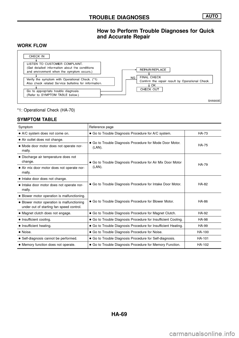
WORK FLOW
*1: Operational Check (HA-70)
SYMPTOM TABLE
Symptom Reference page
+A/C system does not come on.+Go to Trouble Diagnosis Procedure for A/C system. HA-73
+Air outlet does not change.
+Go to Trouble Diagnosis Procedure for Mode Door Motor.
(LAN).HA-75
+Mode door motor does not operate nor-
mally.
+Discharge air temperature does not
change.
+Go to Trouble Diagnosis Procedure for Air Mix Door Motor
(LAN).HA-79
+Air mix door motor does not operate nor-
mally.
+Intake door does not change.
+Go to Trouble Diagnosis Procedure for Intake Door Motor. HA-82
+Intake door motor does not operate nor-
mally.
+Blower motor operation is malfunctioning.
+Go to Trouble Diagnosis Procedure for Blower Motor. HA-86
+Blower motor operation is malfunctioning
under out of starting fan speed control.
+Magnet clutch does not engage.+Go to Trouble Diagnosis Procedure for Magnet Clutch. HA-92
+Insufficient cooling.+Go to Trouble Diagnosis Procedure for Insufficient Cooling. HA-98
+Insufficient heating.+Go to Trouble Diagnosis Procedure for Insufficient Heating. HA-99
+Noise.+Go to Trouble Diagnosis Procedure for Noise. HA-100
+Self-diagnosis cannot be performed.+Go to Trouble Diagnosis Procedure for Self-diagnosis. HA-101
+Memory function does not operate.+Go to Trouble Diagnosis Procedure for Memory Function. HA-102
SHA900E
TROUBLE DIAGNOSESAUTO
HA-69
Page 101 of 128

Insufficient Heating
TROUBLE DIAGNOSIS PROCEDURE FOR INSUFFICIENT HEATING
SYMPTOM:
+Insufficient heating.
Inspection ¯ow
*1: HA-70
*2: HA-64
*3: HA-65
*4: HA-67*5: HA-75
*6: HA-85
*7: HA-89*8: HA-94
*9: HA-79
*10: HA-68
SHA024F
TROUBLE DIAGNOSESAUTO
HA-99