1998 NISSAN PATROL wiring
[x] Cancel search: wiringPage 1 of 128

HEATER &
AIR CONDITIONER
SECTION
HA
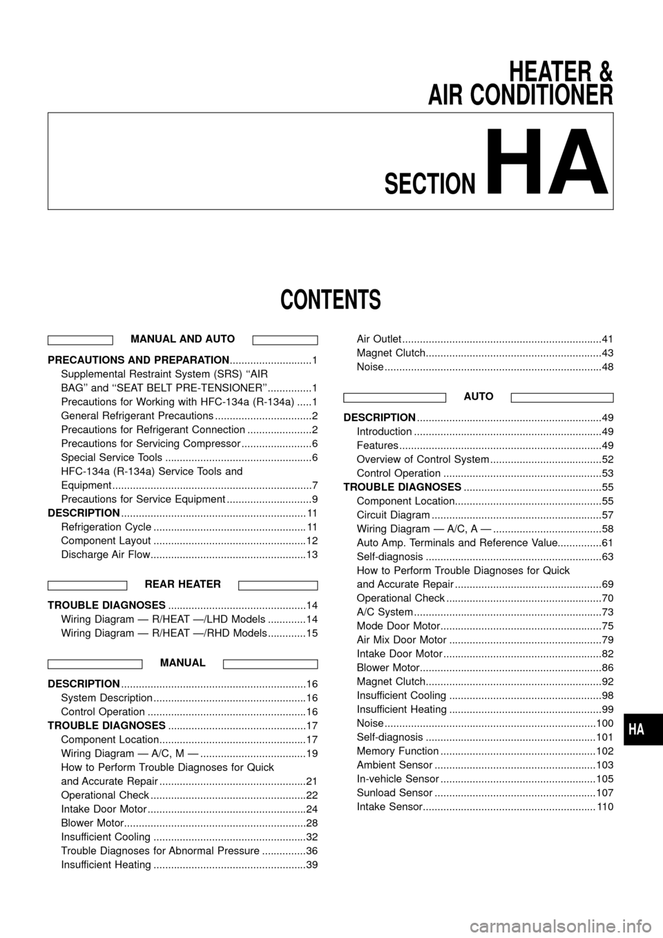
CONTENTS
MANUAL AND AUTO
PRECAUTIONS AND PREPARATION............................1
Supplemental Restraint System (SRS) ``AIR
BAG'' and ``SEAT BELT PRE-TENSIONER'' ...............1
Precautions for Working with HFC-134a (R-134a) .....1
General Refrigerant Precautions .................................2
Precautions for Refrigerant Connection ......................2
Precautions for Servicing Compressor ........................6
Special Service Tools ..................................................6
HFC-134a (R-134a) Service Tools and
Equipment ....................................................................7
Precautions for Service Equipment .............................9
DESCRIPTION............................................................... 11
Refrigeration Cycle .................................................... 11
Component Layout ....................................................12
Discharge Air Flow.....................................................13
REAR HEATER
TROUBLE DIAGNOSES...............................................14
Wiring Diagram Ð R/HEAT Ð/LHD Models .............14
Wiring Diagram Ð R/HEAT Ð/RHD Models .............15
MANUAL
DESCRIPTION...............................................................16
System Description ....................................................16
Control Operation ......................................................16
TROUBLE DIAGNOSES...............................................17
Component Location..................................................17
Wiring Diagram Ð A/C, M Ð ....................................19
How to Perform Trouble Diagnoses for Quick
and Accurate Repair ..................................................21
Operational Check .....................................................22
Intake Door Motor ......................................................24
Blower Motor..............................................................28
Insufficient Cooling ....................................................32
Trouble Diagnoses for Abnormal Pressure ...............36
Insufficient Heating ....................................................39Air Outlet ....................................................................41
Magnet Clutch............................................................43
Noise ..........................................................................48
AUTO
DESCRIPTION...............................................................49
Introduction ................................................................49
Features .....................................................................49
Overview of Control System ......................................52
Control Operation ......................................................53
TROUBLE DIAGNOSES...............................................55
Component Location..................................................55
Circuit Diagram ..........................................................57
Wiring Diagram Ð A/C, A Ð .....................................58
Auto Amp. Terminals and Reference Value...............61
Self-diagnosis ............................................................63
How to Perform Trouble Diagnoses for Quick
and Accurate Repair ..................................................69
Operational Check .....................................................70
A/C System ................................................................73
Mode Door Motor.......................................................75
Air Mix Door Motor ....................................................79
Intake Door Motor ......................................................82
Blower Motor..............................................................86
Magnet Clutch............................................................92
Insufficient Cooling ....................................................98
Insufficient Heating ....................................................99
Noise ........................................................................100
Self-diagnosis ..........................................................101
Memory Function .....................................................102
Ambient Sensor .......................................................103
In-vehicle Sensor .....................................................105
Sunload Sensor .......................................................107
Intake Sensor........................................................... 110
HA
Page 2 of 128

MANUAL AND AUTO
SERVICE PROCEDURES........................................... 112
HFC-134a (R-134a) Service Procedure .................. 112
Maintenance of Lubricant Quantity in
Compressor ............................................................. 114
Ventilation Air Filter .................................................. 116
Refrigerant Lines ..................................................... 117Checking Refrigerant Leaks .................................... 119
Compressor Mounting .............................................122
Compressor Ð DKS-17CH......................................123
Compressor Clutch ..................................................123
SERVICE DATA AND SPECIFICATIONS...................126
General Speci®cations .............................................126
Inspection and Adjustment ......................................126
When you read wiring diagrams:
+Read GI section, ``HOW TO READ WIRING DIAGRAMS''.
+See EL section, ``POWER SUPPLY ROUTING'' for power distribution circuit.
When you perform trouble diagnoses, read GI section, ``HOW TO FOLLOW FLOW
CHART IN TROUBLE DIAGNOSES'' and ``HOW TO PERFORM EFFICIENT DIAGNOSIS
FOR AN ELECTRICAL INCIDENT''.
Page 3 of 128

Supplemental Restraint System (SRS) ``AIR
BAG'' and ``SEAT BELT PRE-TENSIONER''
The Supplemental Restraint System such as ``AIR BAG'' and ``SEAT BELT PRE-TENSIONER'' used along with
a seat belt, helps to reduce the risk or severity of injury to the driver and front passenger in a frontal collision.
The SRS system composition which is available to NISSAN MODEL Y61 is as follows (The composition var-
ies according to the destination.):
Driver air bag module (located in the center of the steering wheel), front passenger air bag module (located
on the instrument panel on passenger side), seat belt pre-tensioner, a diagnosis sensor unit, warning lamp,
wiring harness and spiral cable.
Information necessary to service the system safely is included in theRS sectionof this Service Manual.
WARNING:
+To avoid rendering the SRS inoperative, which could increase the risk of personal injury or death
in the event of a collision which would result in air bag in¯ation, all maintenance must be performed
by an authorized NISSAN dealer.
+Improper maintenance, including incorrect removal and installation of the SRS, can lead to per-
sonal injury caused by unintentional activation of the system. For removal of Spiral Cable and Air
Bag Module, see the RS section.
+Do not use electrical test equipment on any circuit related to the SRS unless instructed to in this
Service Manual. Spiral cable and wiring harnesses covered with yellow insulation either just before
the harness connectors or for the complete harness are related to the SRS.
Precautions for Working with HFC-134a
(R-134a)
WARNING:
+CFC-12 (R-12) refrigerant and HFC-134a (R-134a) refrigerant are not compatible. These refriger-
ants must never be mixed, even in the smallest amounts. If the refrigerants are mixed, compres-
sor failure is likely to occur.
+Use only speci®ed lubricant for the HFC-134a (R-134a) A/C system and HFC-134a (R-134a) com-
ponents. If lubricant other than that speci®ed is used, compressor failure is likely to occur.
+The speci®ed HFC-134a (R-134a) lubricant rapidly absorbs moisture from the atmosphere. The
following handling precautions must be observed:
a: When removing refrigerant components from a vehicle, immediately cap (seal) the component
to minimize the entry of moisture from the atmosphere.
b: When installing refrigerant components to a vehicle, do not remove the caps (unseal) until
just before connecting the components. Connect all refrigerant loop components as quickly
as possible to minimize the entry of moisture into system.
c: Only use the speci®ed lubricant from a sealed container. Immediately reseal containers of
lubricant. Without proper sealing, lubricant will become moisture saturated and should not
be used.
d: Avoid breathing A/C refrigerant and lubricant vapor or mist. Exposure may irritate eyes, nose
and throat. Use only approved recovery/recycling equipment to discharge HFC-134a (R-134a)
refrigerant. If accidental system discharge occurs, ventilate work area before resuming ser-
vice. Additional health and safety information may be obtained from refrigerant and lubricant
manufacturers.
e: Do not allow lubricant (Nissan A/C System Oil Type S) to come in contact with styrofoam
parts. Damage may result.
PRECAUTIONS AND PREPARATIONMANUAL AND AUTO
HA-1
Page 16 of 128

Wiring Diagram Ð R/HEAT Ð/LHD Models
THA165
TROUBLE DIAGNOSESREAR HEATER
HA-14
Page 17 of 128

Wiring Diagram Ð R/HEAT Ð/RHD Models
THA166
TROUBLE DIAGNOSESREAR HEATER
HA-15
Page 21 of 128

Wiring Diagram Ð A/C, M Ð
YHA157
TROUBLE DIAGNOSESMANUAL
HA-19
Page 22 of 128

YHA158
TROUBLE DIAGNOSESMANUAL
Wiring Diagram Ð A/C, M Ð (Cont'd)
HA-20
Page 28 of 128

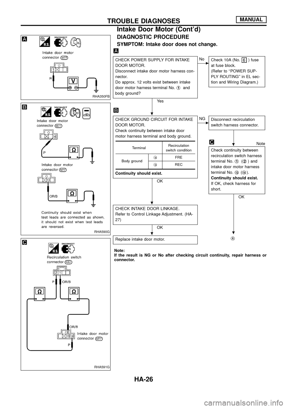
DIAGNOSTIC PROCEDURE
SYMPTOM: Intake door does not change.
CHECK POWER SUPPLY FOR INTAKE
DOOR MOTOR.
Disconnect intake door motor harness con-
nector.
Do approx. 12 volts exist between intake
door motor harness terminal No.j
1and
body ground?
Ye s
cNo
Check 10A (No.) fuse
at fuse block.
(Refer to ``POWER SUP-
PLY ROUTING'' in EL sec-
tion and Wiring Diagram.)
CHECK GROUND CIRCUIT FOR INTAKE
DOOR MOTOR.
Check continuity between intake door
motor harness terminal and body ground.
Continuity should exist.
OK
cNG
Disconnect recirculation
switch harness connector.
Note
Check continuity between
recirculation switch harness
terminal No.j
1(j2) and
intake door motor harness
terminal No.j
13(j14).
Continuity should exist.
If OK, check harness for
short.
OK
CHECK INTAKE DOOR LINKAGE.
Refer to Control Linkage Adjustment. (HA-
27)
OK
Replace intake door motor.
jA
TerminalRecirculation
switch condition
Body groundj
14FRE
j
13REC
Note:
If the result is NG or No after checking circuit continuity, repair harness or
connector.
RHA350FB
RHA590G
RHA591G
.
.
.
..
TROUBLE DIAGNOSESMANUAL
Intake Door Motor (Cont'd)
HA-26