1998 NISSAN PATROL AC hoses
[x] Cancel search: AC hosesPage 9 of 128

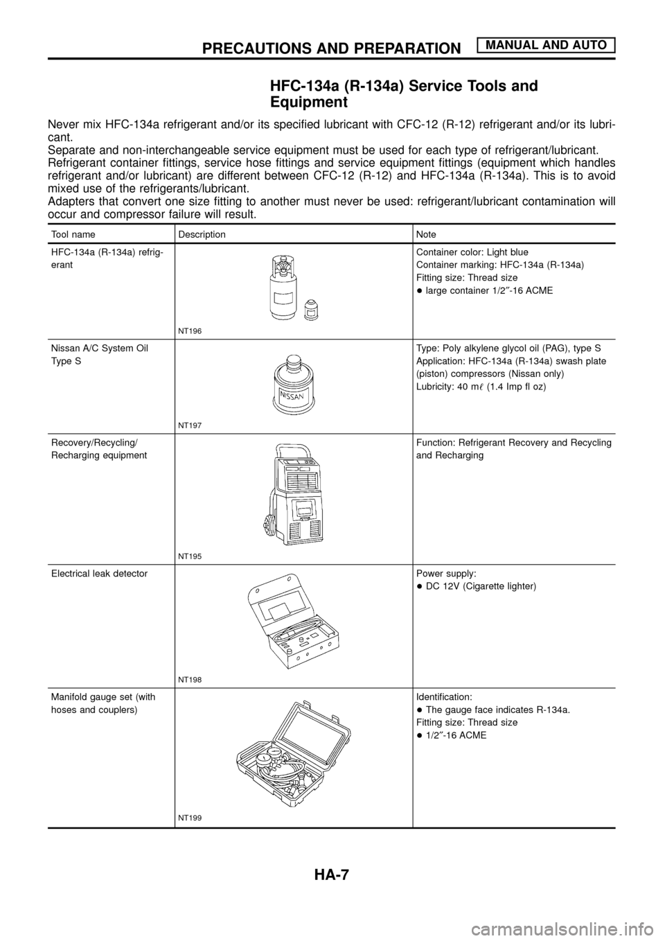
HFC-134a (R-134a) Service Tools and
Equipment
Never mix HFC-134a refrigerant and/or its speci®ed lubricant with CFC-12 (R-12) refrigerant and/or its lubri-
cant.
Separate and non-interchangeable service equipment must be used for each type of refrigerant/lubricant.
Refrigerant container ®ttings, service hose ®ttings and service equipment ®ttings (equipment which handles
refrigerant and/or lubricant) are different between CFC-12 (R-12) and HFC-134a (R-134a). This is to avoid
mixed use of the refrigerants/lubricant.
Adapters that convert one size ®tting to another must never be used: refrigerant/lubricant contamination will
occur and compressor failure will result.
Tool name Description Note
HFC-134a (R-134a) refrig-
erant
NT196
Container color: Light blue
Container marking: HFC-134a (R-134a)
Fitting size: Thread size
+large container 1/2²-16 ACME
Nissan A/C System Oil
Type S
NT197
Type: Poly alkylene glycol oil (PAG), type S
Application: HFC-134a (R-134a) swash plate
(piston) compressors (Nissan only)
Lubricity: 40 m!(1.4 Imp ¯ oz)
Recovery/Recycling/
Recharging equipment
NT195
Function: Refrigerant Recovery and Recycling
and Recharging
Electrical leak detector
NT198
Power supply:
+DC 12V (Cigarette lighter)
Manifold gauge set (with
hoses and couplers)
NT199
Identi®cation:
+The gauge face indicates R-134a.
Fitting size: Thread size
+1/2²-16 ACME
PRECAUTIONS AND PREPARATIONMANUAL AND AUTO
HA-7
Page 10 of 128

Tool name Description Note
Service hoses
+High side hose
+Low side hose
+Utility hose
NT201
Hose color:
+Low hose: Blue with black stripe
+High hose: Red with black stripe
+Utility hose: Yellow with black stripe or
green with black stripe
Hose ®tting to gauge:
+1/2²-16 ACME
Service couplers
+High side coupler
+Low side coupler
NT202
Hose ®tting to service hose:
+M14 x 1.5 ®tting is optional or
permanently attached.
Refrigerant weight scale
NT200
For measuring of refrigerant
Fitting size: Thread size
+1/2²-16 ACME
Vacuum pump
(Including the isolator
valve)
NT203
Capacity:
+Air displacement: 4 CFM
+Micron rating: 20 microns
+Oil capacity: 482 g (17 oz)
Fitting size: Thread size
+1/2²-16 ACME
PRECAUTIONS AND PREPARATIONMANUAL AND AUTO
HFC-134a (R-134a) Service Tools and
Equipment (Cont'd)
HA-8
Page 11 of 128

Precautions for Service Equipment
RECOVERY/RECYCLING EQUIPMENT
Follow the manufacturer's instructions for machine operation and
machine maintenance. Never introduce any refrigerant other than
that speci®ed into the machine.
ELECTRONIC LEAK DETECTOR
Follow the manufacture's instructions for tester operation and tester
maintenance.
VACUUM PUMP
The lubricant contained inside the vacuum pump is not compatible
with the speci®ed lubricant for HFC-134a (R-134a) A/C systems.
The vent side of the vacuum pump is exposed to atmospheric
pressure. So the vacuum pump lubricant may migrate out of the
pump into the service hose. This is possible when the pump is
switched off after evacuation (vacuuming) and hose is connected
to it.
To prevent this migration, use a manual valve situated near the
hose-to-pump connection, as follows.
+Usually vacuum pumps have a manual isolator valve as part of
the pump. Close this valve to isolate the service hose from the
pump.
+For pumps without an isolator, use a hose equipped with a
manual shut-off valve near the pump end. Close the valve to
isolate the hose from the pump.
+If the hose has an automatic shut off valve, disconnect the hose
from the pump: as long as the hose is connected, the valve is
open and lubricating oil may migrate.
Some one-way valves open when vacuum is applied and close
under a no vacuum condition. Such valves may restrict the pump's
ability to pull a deep vacuum and are not recommended.
MANIFOLD GAUGE SET
Be certain that the gauge face indicates R-134a or 134a. Make
sure the gauge set has 1/2²-16 ACME threaded connections for
service hoses. Con®rm the set has been used only with refrigerant
HFC-134a (R-134a) along with speci®ed lubricant.
SERVICE HOSES
Be certain that the service hoses display the markings described
(colored hose with black stripe). All hoses must include positive
shut off devices (either manual or automatic) near the end of the
hoses opposite the manifold gauge.
RHA270D
SHA533D
RHA272D
PRECAUTIONS AND PREPARATIONMANUAL AND AUTO
HA-9
Page 114 of 128

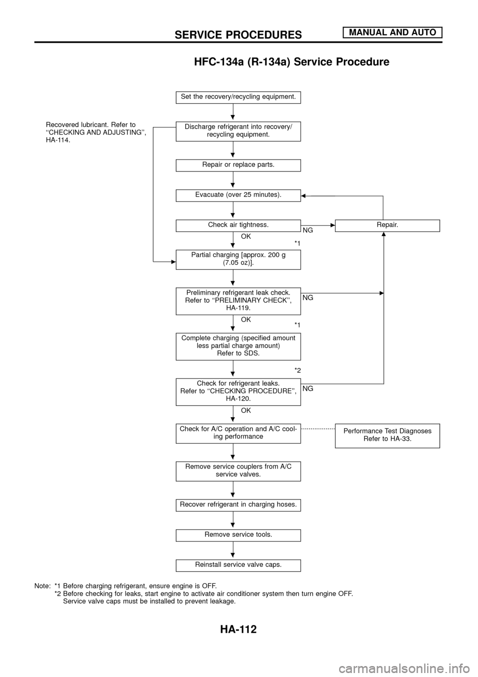
HFC-134a (R-134a) Service Procedure
Set the recovery/recycling equipment.
Recovered lubricant. Refer to
``CHECKING AND ADJUSTING'',
HA-114.
c
Discharge refrigerant into recovery/
recycling equipment.
Repair or replace parts.
Evacuate (over 25 minutes).b
Check air tightness.
OK
*1
cNGRepair.m
Partial charging [approx. 200 g
(7.05 oz)].
Preliminary refrigerant leak check.
Refer to ``PRELIMINARY CHECK'',
HA-119.
OK
*1
cNG
Complete charging (speci®ed amount
less partial charge amount)
Refer to SDS.
*2
Check for refrigerant leaks.
Refer to ``CHECKING PROCEDURE'',
HA-120.
OK
NG
Check for A/C operation and A/C cool-
ing performance..................
Performance Test Diagnoses
Refer to HA-33.
Remove service couplers from A/C
service valves.
Recover refrigerant in charging hoses.
Remove service tools.
Reinstall service valve caps.
Note: *1 Before charging refrigerant, ensure engine is OFF.
*2 Before checking for leaks, start engine to activate air conditioner system then turn engine OFF.
Service valve caps must be installed to prevent leakage.
.
.
.
.
.
.
.
.
.
.
.
.
.
SERVICE PROCEDURESMANUAL AND AUTO
HA-112
Page 121 of 128

Checking Refrigerant Leaks
PRELIMINARY CHECK
Perform a visual inspection of all refrigeration parts, ®ttings, hoses,
and components for signs of A/C lubricant leakage, damage and
corrosion.
PRECAUTIONS FOR HANDLING LEAK DETECTOR
When performing a refrigerant leak check, use an A/C leak detec-
tor or equivalent. Ensure that the instrument is calibrated and set
properly per the operating instructions.
The leak detector is a delicate device. In order to use the leak
detector properly, read the operating instructions and perform any
speci®ed maintenance.
Other gases in the work area or substances on the A/C
components, for example, anti-freeze, windshield washer
¯uid, solvents and cleaners, may falsely trigger the leak detec-
tor. Make sure the surfaces to be checked are clean. Do not
allow the sensor tip of the detector to come into contact with
any substance. This can also cause false readings and may
damage the detector.
1. Position probe approximately 5 mm (3/16 in) away from point
to be checked.
2. When testing, circle each ®tting completely with probe.
SHA705EB
SHA707EA
SHA706E
SERVICE PROCEDURESMANUAL AND AUTO
HA-119
Page 122 of 128

3. Move probe along component approximately 25 to 50 mm (1 to
2 in)/sec.
CHECKING PROCEDURE
To prevent inaccurate or false readings, make sure there is no
refrigerant vapor or tobacco smoke in the vicinity of the
vehicle. Perform the leak test in calm area (low air/wind move-
ment) so that the leaking refrigerant is not dispersed.
1. Turn engine off.
2. Connect a suitable A/C manifold gauge set to the A/C service
ports.
3. Check if the A/C refrigerant pressure is at least 345 kPa (3.452
bar, 3.52 kg/cm
2, 50 psi) above 16ÉC (61ÉF). If less than
speci®cation, evacuate and recharge the system with the speci-
®ed amount of refrigerant.
NOTE: At temperatures below 16ÉC (61ÉF), leaks may not be
detected since the system may not reach 345 kPa
(3.452 bar, 3.52 kg/cm
2, 50 psi).
4. Conduct the leak test from the high side to the low side at points
in alphabetical order (j
a,jb......). Refer to HA-117.
Perform a leak check for the following areas carefully. Clean the
component to be checked and move the leak detector probe
completely around the connection/component.
+Compressor
Check the ®tting of high and low pressure hoses, relief valve
and shaft seal.
+Liquid tank
Check the pressure switch, tube ®tting, weld seams and the
fusible plug mounts.
+Service valves
Check all around the service valves. Ensure service valve caps
are secured on the service valves (to prevent leaks).
NOTE: After removing A/C manifold gauge set from service
valves, wipe any residue from valves to prevent any
false readings by leak detector.
+Cooling unit (Evaporator)
Turn blower fan on ``High'' for at least 15 seconds to dissipate
any refrigerant trace in the cooling unit. Insert the leak detector
probe into the drain hose immediately after stopping the
engine. (Keep the probe inserted for at least ten seconds.)
5. If a leak detector detects a leak, verify at least once by blowing
compressed air into area of suspected leak, then repeat check.
6. Do not stop when one leak is found. Continue to check for
additional leaks at all system components.
7. Start engine.
8. Set the heater A/C control as follows:
a. A/C switch ON
b. Face mode
c. Recirculation switch ON
d. Max cold temperature
e. Fan speed high
SHA708EA
SERVICE PROCEDURESMANUAL AND AUTO
Checking Refrigerant Leaks (Cont'd)
HA-120