1998 NISSAN PATROL battery
[x] Cancel search: batteryPage 236 of 326
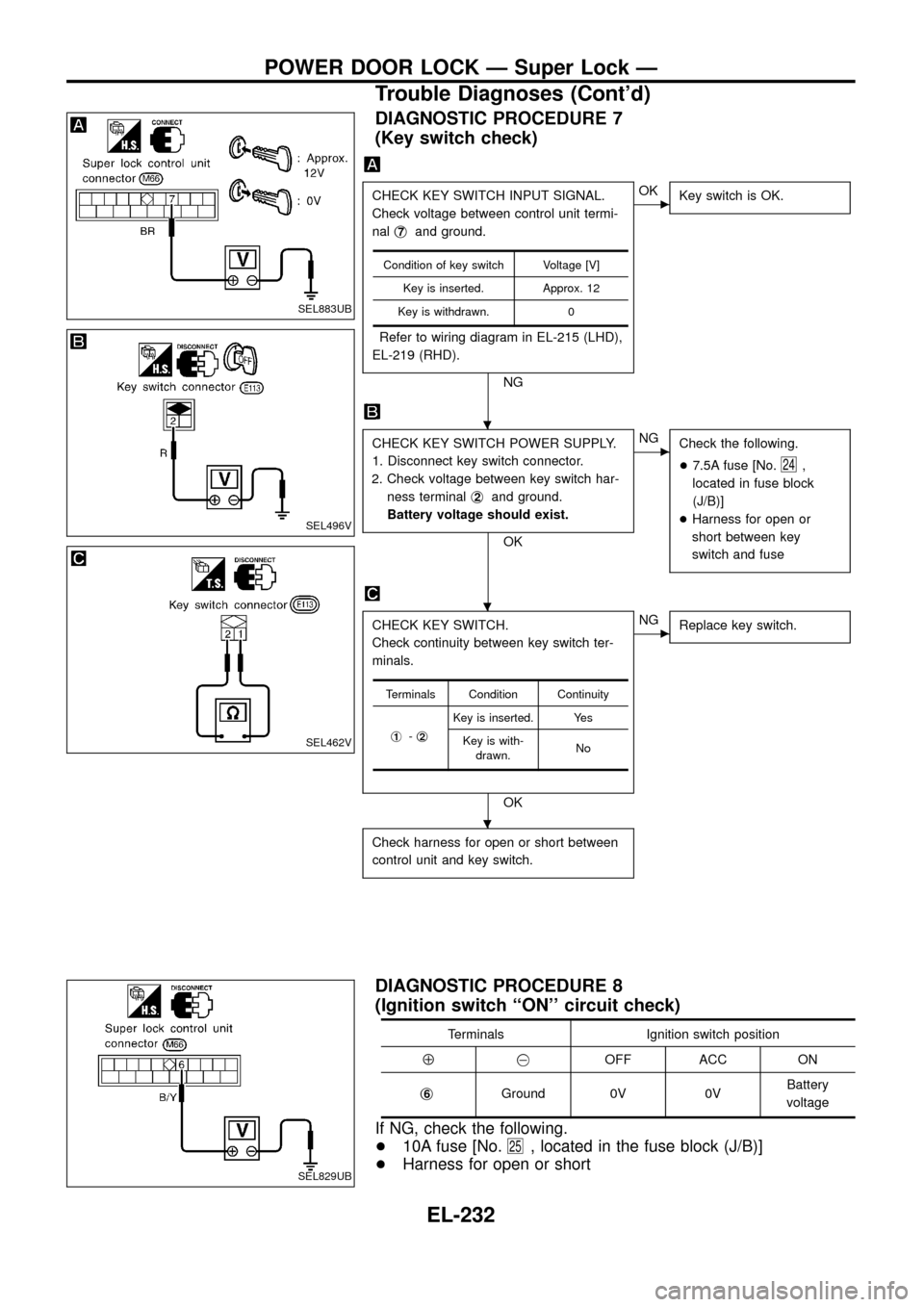
DIAGNOSTIC PROCEDURE 7
(Key switch check)
CHECK KEY SWITCH INPUT SIGNAL.
Check voltage between control unit termi-
nalj
7and ground.
Refer to wiring diagram in EL-215 (LHD),
EL-219 (RHD).
NG
cOK
Key switch is OK.
CHECK KEY SWITCH POWER SUPPLY.
1. Disconnect key switch connector.
2. Check voltage between key switch har-
ness terminalj
2and ground.
Battery voltage should exist.
OK
cNG
Check the following.
+7.5A fuse [No.
24,
located in fuse block
(J/B)]
+Harness for open or
short between key
switch and fuse
CHECK KEY SWITCH.
Check continuity between key switch ter-
minals.
OK
cNG
Replace key switch.
Check harness for open or short between
control unit and key switch.
Condition of key switch Voltage [V]
Key is inserted. Approx. 12
Key is withdrawn. 0
Terminals Condition Continuity
j
1-j2
Key is inserted. Yes
Key is with-
drawn.No
DIAGNOSTIC PROCEDURE 8
(Ignition switch ``ON'' circuit check)
Terminals Ignition switch position
Å@OFF ACC ON
j
6Ground 0V 0VBattery
voltage
If NG, check the following.
+10A fuse [No.
25, located in the fuse block (J/B)]
+Harness for open or short
SEL883UB
SEL496V
SEL462V
SEL829UB
.
.
.
POWER DOOR LOCK Ð Super Lock Ð
Trouble Diagnoses (Cont'd)
EL-232
Page 241 of 326
Trouble Diagnoses
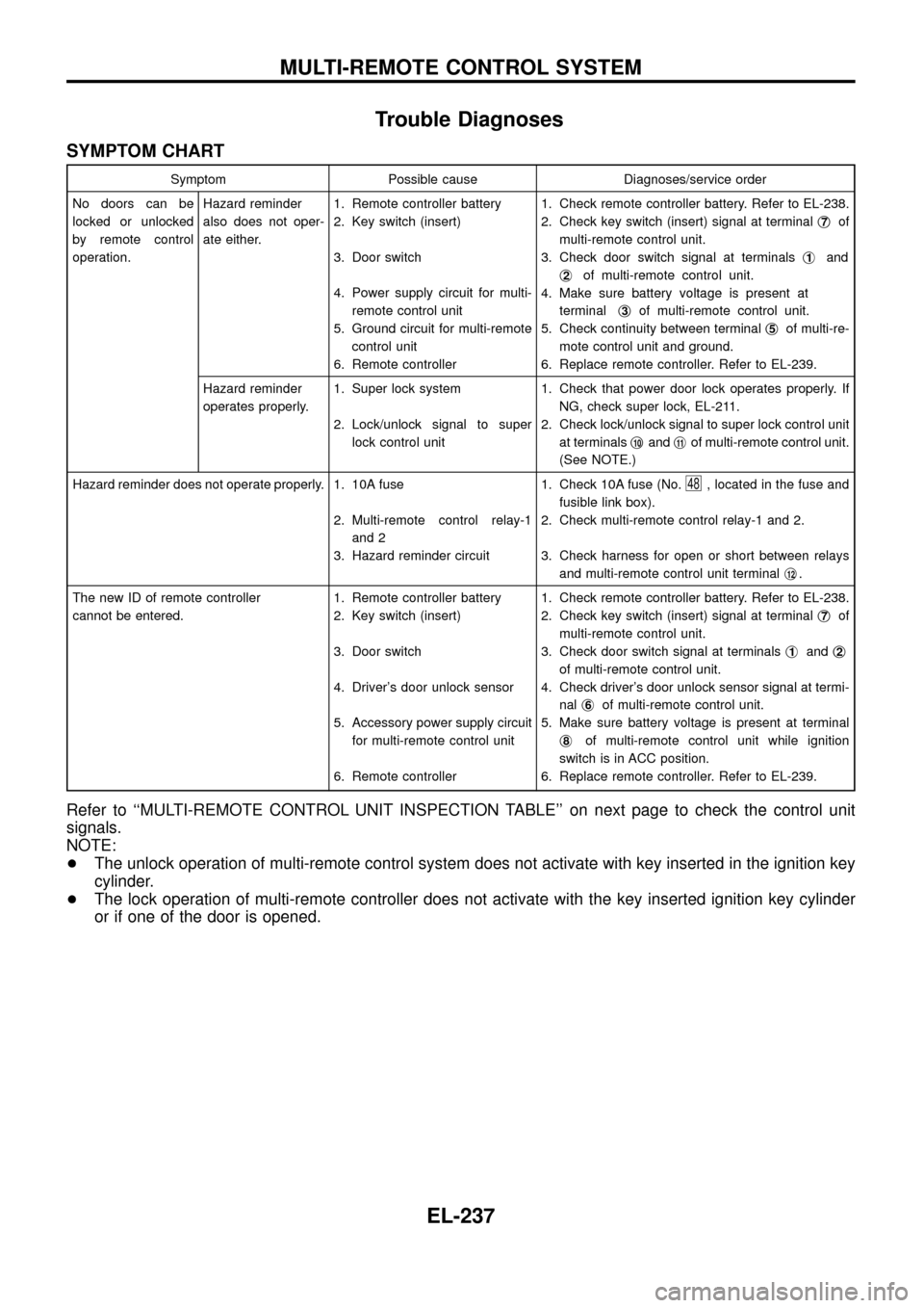
SYMPTOM CHART
Symptom Possible cause Diagnoses/service order
No doors can be
locked or unlocked
by remote control
operation.Hazard reminder
also does not oper-
ate either.1. Remote controller battery
2. Key switch (insert)
3. Door switch
4. Power supply circuit for multi-
remote control unit
5. Ground circuit for multi-remote
control unit
6. Remote controller1. Check remote controller battery. Refer to EL-238.
2. Check key switch (insert) signal at terminalj
7of
multi-remote control unit.
3. Check door switch signal at terminalsj
1and
j
2of multi-remote control unit.
4. Make sure battery voltage is present at
terminalj
3of multi-remote control unit.
5. Check continuity between terminalj
5of multi-re-
mote control unit and ground.
6. Replace remote controller. Refer to EL-239.
Hazard reminder
operates properly.1. Super lock system
2. Lock/unlock signal to super
lock control unit1. Check that power door lock operates properly. If
NG, check super lock, EL-211.
2. Check lock/unlock signal to super lock control unit
at terminalsj
10andj11of multi-remote control unit.
(See NOTE.)
Hazard reminder does not operate properly. 1. 10A fuse
2. Multi-remote control relay-1
and 2
3. Hazard reminder circuit1. Check 10A fuse (No.
48, located in the fuse and
fusible link box).
2. Check multi-remote control relay-1 and 2.
3. Check harness for open or short between relays
and multi-remote control unit terminalj
12.
The new ID of remote controller
cannot be entered.1. Remote controller battery
2. Key switch (insert)
3. Door switch
4. Driver's door unlock sensor
5. Accessory power supply circuit
for multi-remote control unit
6. Remote controller1. Check remote controller battery. Refer to EL-238.
2. Check key switch (insert) signal at terminalj
7of
multi-remote control unit.
3. Check door switch signal at terminalsj
1andj2
of multi-remote control unit.
4. Check driver's door unlock sensor signal at termi-
nalj
6of multi-remote control unit.
5. Make sure battery voltage is present at terminal
j
8of multi-remote control unit while ignition
switch is in ACC position.
6. Replace remote controller. Refer to EL-239.
Refer to ``MULTI-REMOTE CONTROL UNIT INSPECTION TABLE'' on next page to check the control unit
signals.
NOTE:
+The unlock operation of multi-remote control system does not activate with key inserted in the ignition key
cylinder.
+The lock operation of multi-remote controller does not activate with the key inserted ignition key cylinder
or if one of the door is opened.
MULTI-REMOTE CONTROL SYSTEM
EL-237
Page 242 of 326
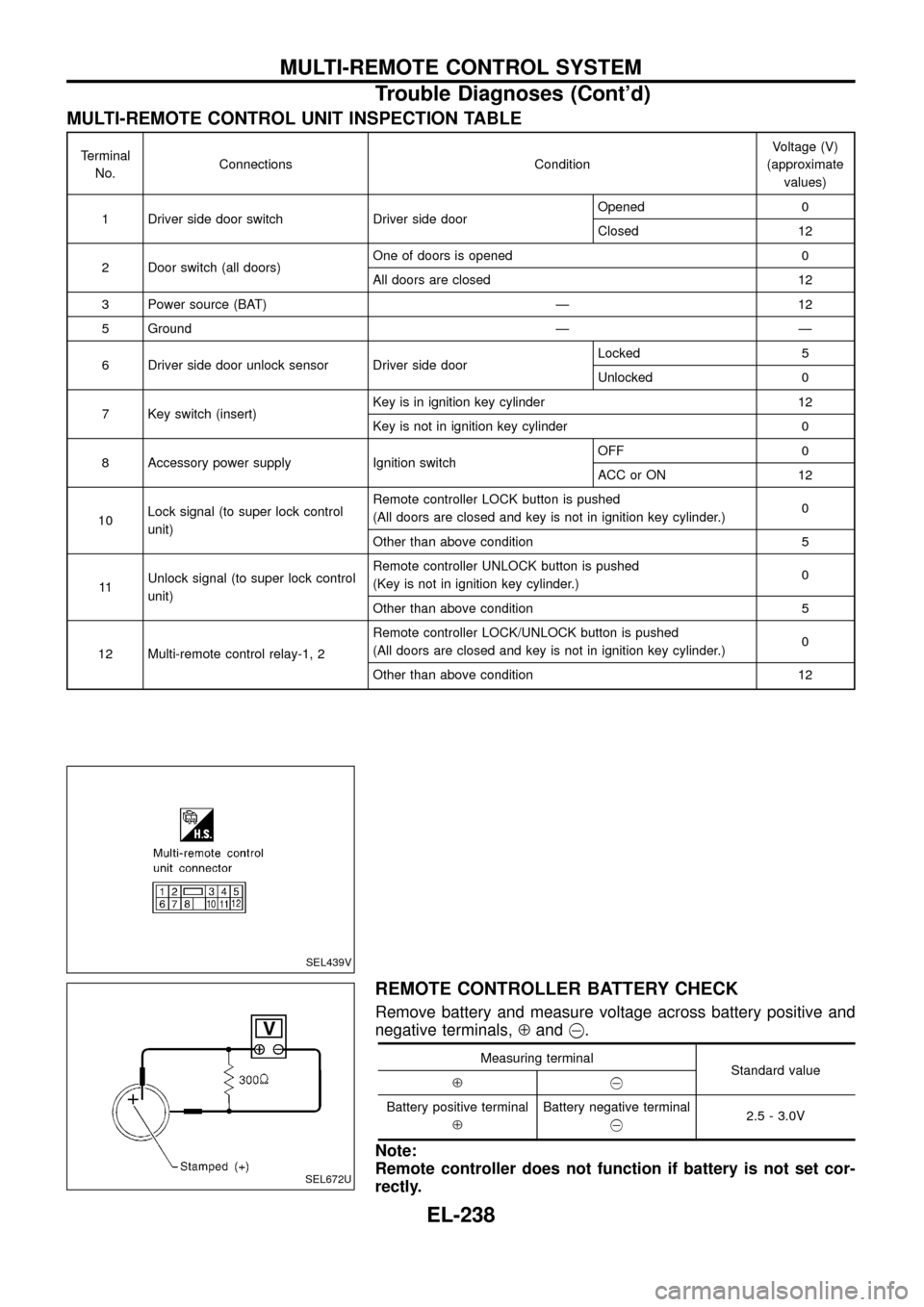
MULTI-REMOTE CONTROL UNIT INSPECTION TABLE
Terminal
No.Connections ConditionVoltage (V)
(approximate
values)
1 Driver side door switch Driver side doorOpened 0
Closed 12
2 Door switch (all doors)One of doors is opened 0
All doors are closed 12
3 Power source (BAT) Ð 12
5 Ground Ð Ð
6 Driver side door unlock sensor Driver side doorLocked 5
Unlocked 0
7 Key switch (insert)Key is in ignition key cylinder 12
Key is not in ignition key cylinder 0
8 Accessory power supply Ignition switchOFF 0
ACC or ON 12
10Lock signal (to super lock control
unit)Remote controller LOCK button is pushed
(All doors are closed and key is not in ignition key cylinder.)0
Other than above condition 5
11Unlock signal (to super lock control
unit)Remote controller UNLOCK button is pushed
(Key is not in ignition key cylinder.)0
Other than above condition 5
12 Multi-remote control relay-1, 2Remote controller LOCK/UNLOCK button is pushed
(All doors are closed and key is not in ignition key cylinder.)0
Other than above condition 12
REMOTE CONTROLLER BATTERY CHECK
Remove battery and measure voltage across battery positive and
negative terminals,Åand@.
Measuring terminal
Standard value
Å@
Battery positive terminal
ÅBattery negative terminal
@2.5 - 3.0V
Note:
Remote controller does not function if battery is not set cor-
rectly.
SEL439V
SEL672U
MULTI-REMOTE CONTROL SYSTEM
Trouble Diagnoses (Cont'd)
EL-238
Page 249 of 326
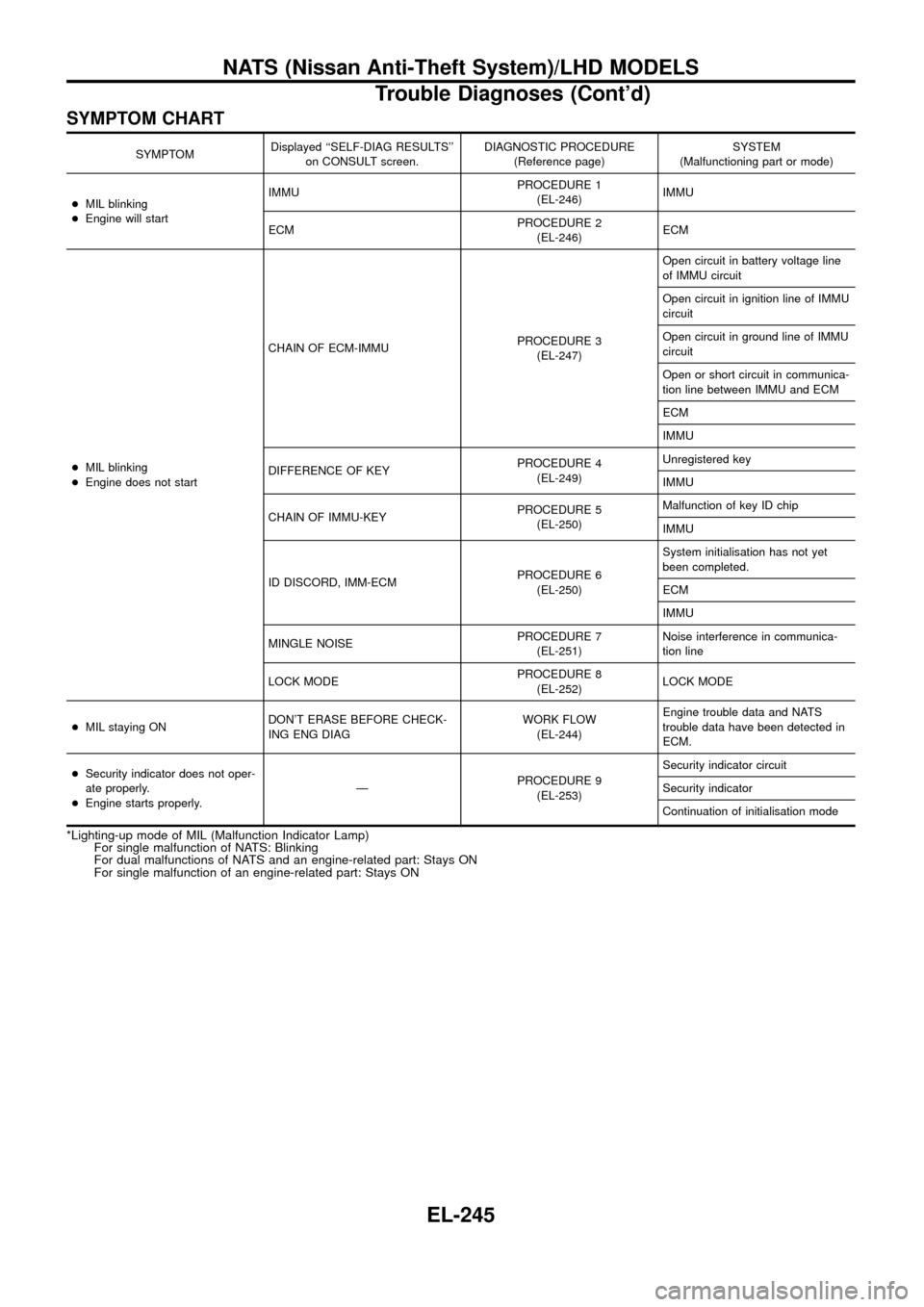
SYMPTOM CHART
SYMPTOMDisplayed ``SELF-DIAG RESULTS''
on CONSULT screen.DIAGNOSTIC PROCEDURE
(Reference page)SYSTEM
(Malfunctioning part or mode)
+MIL blinking
+Engine will startIMMUPROCEDURE 1
(EL-246)IMMU
ECMPROCEDURE 2
(EL-246)ECM
+MIL blinking
+Engine does not startCHAIN OF ECM-IMMUPROCEDURE 3
(EL-247)Open circuit in battery voltage line
of IMMU circuit
Open circuit in ignition line of IMMU
circuit
Open circuit in ground line of IMMU
circuit
Open or short circuit in communica-
tion line between IMMU and ECM
ECM
IMMU
DIFFERENCE OF KEYPROCEDURE 4
(EL-249)Unregistered key
IMMU
CHAIN OF IMMU-KEYPROCEDURE 5
(EL-250)Malfunction of key ID chip
IMMU
ID DISCORD, IMM-ECMPROCEDURE 6
(EL-250)System initialisation has not yet
been completed.
ECM
IMMU
MINGLE NOISEPROCEDURE 7
(EL-251)Noise interference in communica-
tion line
LOCK MODEPROCEDURE 8
(EL-252)LOCK MODE
+MIL staying ONDON'T ERASE BEFORE CHECK-
ING ENG DIAGWORK FLOW
(EL-244)Engine trouble data and NATS
trouble data have been detected in
ECM.
+Security indicator does not oper-
ate properly.
+Engine starts properly.ÐPROCEDURE 9
(EL-253)Security indicator circuit
Security indicator
Continuation of initialisation mode
*Lighting-up mode of MIL (Malfunction Indicator Lamp)
For single malfunction of NATS: Blinking
For dual malfunctions of NATS and an engine-related part: Stays ON
For single malfunction of an engine-related part: Stays ON
NATS (Nissan Anti-Theft System)/LHD MODELS
Trouble Diagnoses (Cont'd)
EL-245
Page 251 of 326
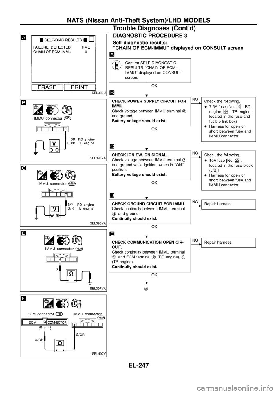
DIAGNOSTIC PROCEDURE 3
Self-diagnostic results:
``CHAIN OF ECM-IMMU'' displayed on CONSULT screen
Con®rm SELF-DIAGNOSTIC
RESULTS ``CHAIN OF ECM-
IMMU'' displayed on CONSULT
screen.
OK
CHECK POWER SUPPLY CIRCUIT FOR
IMMU.
Check voltage between IMMU terminalj
8
and ground.
Battery voltage should exist.
OK
cNG
Check the following.
+7.5A fuse (No.
50:RD
engine,
49: TB engine,
located in the fuse and
fusible link box)
+Harness for open or
short between fuse and
IMMU connector
CHECK IGN SW. ON SIGNAL.
Check voltage between IMMU terminalj
7
and ground while ignition switch is ``ON''
position.
Battery voltage should exist.
OK
cNG
Check the following.
+10A fuse [No.
25,
located in the fuse block
(J/B)]
+Harness for open or
short between fuse and
IMMU connector
CHECK GROUND CIRCUIT FOR IMMU.
Check continuity between IMMU terminal
j
4and ground.
Continuity should exist.
OK
cNG
Repair harness.
CHECK COMMUNICATION OPEN CIR-
CUIT.
Check continuity between IMMU terminal
j
1and ECM terminalj55(RD engine),j11
(TB engine).
Continuity should exist.
OK
cNG
Repair harness.
jA
SEL333U
SEL395VA
SEL396VA
SEL397VA
SEL497V
.
.
.
.
.
NATS (Nissan Anti-Theft System)/LHD MODELS
Trouble Diagnoses (Cont'd)
EL-247
Page 257 of 326
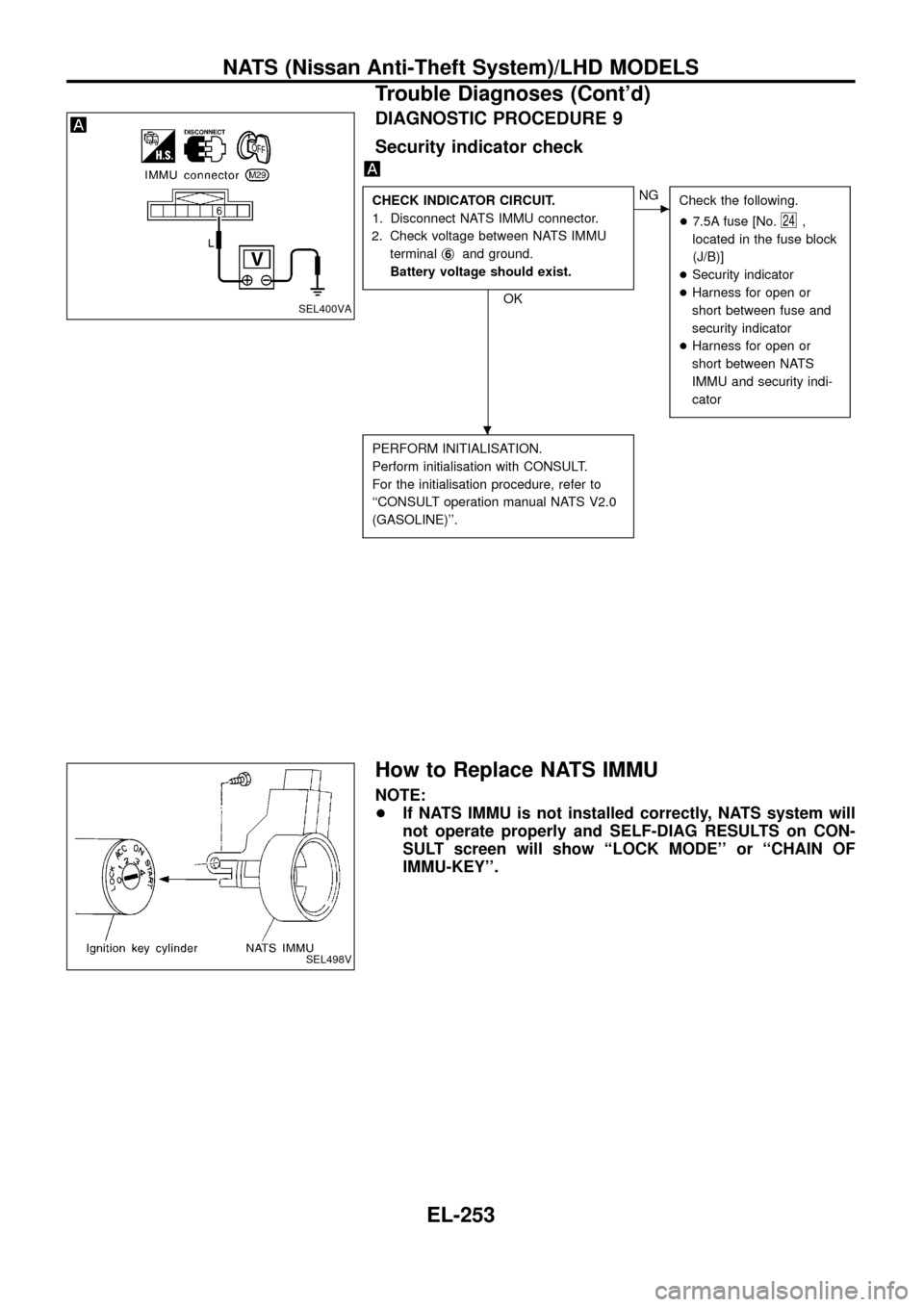
DIAGNOSTIC PROCEDURE 9
Security indicator check
CHECK INDICATOR CIRCUIT.
1. Disconnect NATS IMMU connector.
2. Check voltage between NATS IMMU
terminalj
6and ground.
Battery voltage should exist.
OK
cNG
Check the following.
+7.5A fuse [No.
24,
located in the fuse block
(J/B)]
+Security indicator
+Harness for open or
short between fuse and
security indicator
+Harness for open or
short between NATS
IMMU and security indi-
cator
PERFORM INITIALISATION.
Perform initialisation with CONSULT.
For the initialisation procedure, refer to
``CONSULT operation manual NATS V2.0
(GASOLINE)''.
How to Replace NATS IMMU
NOTE:
+If NATS IMMU is not installed correctly, NATS system will
not operate properly and SELF-DIAG RESULTS on CON-
SULT screen will show ``LOCK MODE'' or ``CHAIN OF
IMMU-KEY''.
SEL400VA
SEL498V
.
NATS (Nissan Anti-Theft System)/LHD MODELS
Trouble Diagnoses (Cont'd)
EL-253
Page 264 of 326
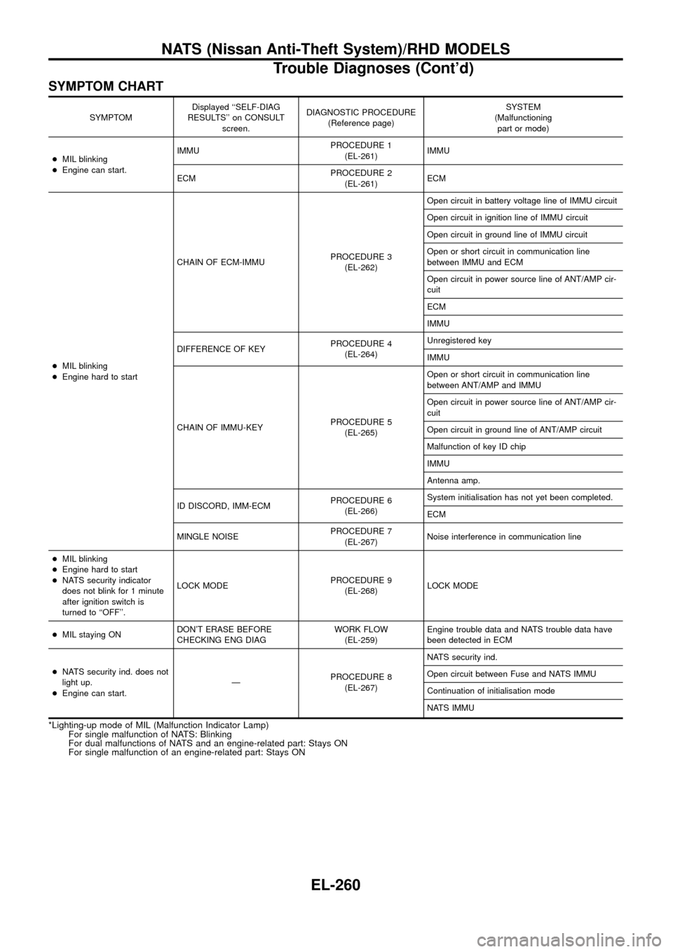
SYMPTOM CHART
SYMPTOMDisplayed ``SELF-DIAG
RESULTS'' on CONSULT
screen.DIAGNOSTIC PROCEDURE
(Reference page)SYSTEM
(Malfunctioning
part or mode)
+MIL blinking
+Engine can start.IMMUPROCEDURE 1
(EL-261)IMMU
ECMPROCEDURE 2
(EL-261)ECM
+MIL blinking
+Engine hard to startCHAIN OF ECM-IMMUPROCEDURE 3
(EL-262)Open circuit in battery voltage line of IMMU circuit
Open circuit in ignition line of IMMU circuit
Open circuit in ground line of IMMU circuit
Open or short circuit in communication line
between IMMU and ECM
Open circuit in power source line of ANT/AMP cir-
cuit
ECM
IMMU
DIFFERENCE OF KEYPROCEDURE 4
(EL-264)Unregistered key
IMMU
CHAIN OF IMMU-KEYPROCEDURE 5
(EL-265)Open or short circuit in communication line
between ANT/AMP and IMMU
Open circuit in power source line of ANT/AMP cir-
cuit
Open circuit in ground line of ANT/AMP circuit
Malfunction of key ID chip
IMMU
Antenna amp.
ID DISCORD, IMM-ECMPROCEDURE 6
(EL-266)System initialisation has not yet been completed.
ECM
MINGLE NOISEPROCEDURE 7
(EL-267)Noise interference in communication line
+MIL blinking
+Engine hard to start
+NATS security indicator
does not blink for 1 minute
after ignition switch is
turned to ``OFF''.LOCK MODEPROCEDURE 9
(EL-268)LOCK MODE
+MIL staying ONDON'T ERASE BEFORE
CHECKING ENG DIAGWORK FLOW
(EL-259)Engine trouble data and NATS trouble data have
been detected in ECM
+NATS security ind. does not
light up.
+Engine can start.ÐPROCEDURE 8
(EL-267)NATS security ind.
Open circuit between Fuse and NATS IMMU
Continuation of initialisation mode
NATS IMMU
*Lighting-up mode of MIL (Malfunction Indicator Lamp)
For single malfunction of NATS: Blinking
For dual malfunctions of NATS and an engine-related part: Stays ON
For single malfunction of an engine-related part: Stays ON
NATS (Nissan Anti-Theft System)/RHD MODELS
Trouble Diagnoses (Cont'd)
EL-260
Page 266 of 326
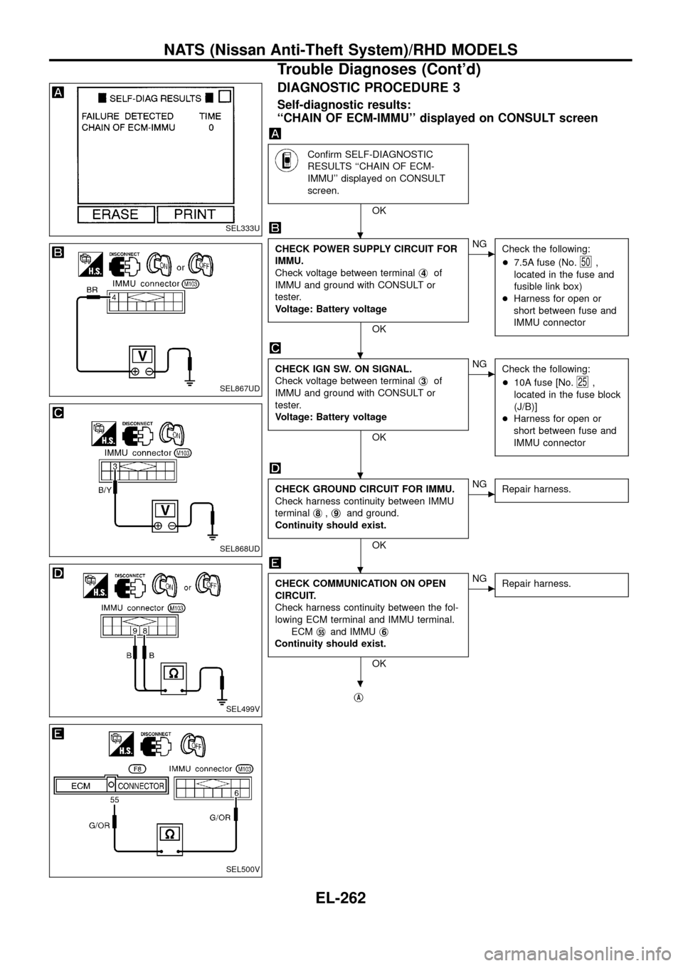
DIAGNOSTIC PROCEDURE 3
Self-diagnostic results:
``CHAIN OF ECM-IMMU'' displayed on CONSULT screen
Con®rm SELF-DIAGNOSTIC
RESULTS ``CHAIN OF ECM-
IMMU'' displayed on CONSULT
screen.
OK
CHECK POWER SUPPLY CIRCUIT FOR
IMMU.
Check voltage between terminalj
4of
IMMU and ground with CONSULT or
tester.
Voltage: Battery voltage
OK
cNG
Check the following:
+7.5A fuse (No.
50,
located in the fuse and
fusible link box)
+Harness for open or
short between fuse and
IMMU connector
CHECK IGN SW. ON SIGNAL.
Check voltage between terminalj
3of
IMMU and ground with CONSULT or
tester.
Voltage: Battery voltage
OK
cNG
Check the following:
+10A fuse [No.
25,
located in the fuse block
(J/B)]
+Harness for open or
short between fuse and
IMMU connector
CHECK GROUND CIRCUIT FOR IMMU.
Check harness continuity between IMMU
terminalj
8,j9and ground.
Continuity should exist.
OK
cNG
Repair harness.
CHECK COMMUNICATION ON OPEN
CIRCUIT.
Check harness continuity between the fol-
lowing ECM terminal and IMMU terminal.
ECMj
55and IMMUj6
Continuity should exist.
OK
cNG
Repair harness.
jA
SEL333U
SEL867UD
SEL868UD
SEL499V
SEL500V
.
.
.
.
.
NATS (Nissan Anti-Theft System)/RHD MODELS
Trouble Diagnoses (Cont'd)
EL-262