1998 NISSAN PATROL Connector 15
[x] Cancel search: Connector 15Page 1 of 326
ELECTRICAL SYSTEM
SECTION
EL
When you read wiring diagrams:
+Read GI section, ``HOW TO READ WIRING DIAGRAMS''.
When you perform trouble diagnoses, read GI section, ``HOW TO FOLLOW FLOW
CHART IN TROUBLE DIAGNOSES'' and ``HOW TO PERFORM EFFICIENT DIAGNOSIS
FOR AN ELECTRICAL INCIDENT''.
+Check for any service bulletins before servicing the vehicle.
CONTENTS
PRECAUTIONS...............................................................1
Supplemental Restraint System (SRS) ``AIR
BAG'' and ``SEAT BELT PRE-TENSIONER''...............1
HARNESS CONNECTOR................................................2
Description ...................................................................2
STANDARDIZED RELAY................................................3
Description ...................................................................3
POWER SUPPLY ROUTING...........................................5
Schematic ....................................................................5
Wiring Diagram Ð POWER Ð....................................6
Fuse ...........................................................................14
Fusible Link................................................................14
Circuit Breaker Inspection .........................................14
GROUND DISTRIBUTION/LHD MODELS....................15
Engine Room Harness ..............................................15
Main Harness.............................................................19
Body Harness ............................................................22
Body No. 2 Harness ..................................................23
Back Door and Rear Window Defogger Harness .....24
Room Lamp Harness.................................................25
GROUND DISTRIBUTION/RHD MODELS...................26
Engine Room Harness ..............................................26
Main Harness.............................................................30
Body Harness ............................................................33
Body No. 2 Harness ..................................................34
Back Door and Rear Window Defogger Harness .....35
Room Lamp Harness.................................................36
BATTERY.......................................................................37
How to Handle Battery ..............................................37
Battery Test and Charging Chart ...............................40
Service Data and Speci®cations (SDS).....................44
STARTING SYSTEM.....................................................45
Wiring Diagram Ð START Ð ....................................45Trouble Diagnoses.....................................................46
Construction ...............................................................47
Removal and Installation ...........................................47
Inspection...................................................................47
Assembly ...................................................................50
Service Data and Speci®cations (SDS).....................51
CHARGING SYSTEM....................................................52
Wiring Diagram Ð CHARGE Ð ................................52
Trouble Diagnoses.....................................................53
Construction ...............................................................54
Removal and Installation ...........................................54
Disassembly...............................................................54
Inspection...................................................................55
Assembly ...................................................................56
Service Data and Speci®cations (SDS).....................56
COMBINATION SWITCH...............................................57
Check .........................................................................57
Replacement ..............................................................58
STEERING SWITCH......................................................59
Check .........................................................................59
HEADLAMP Ð Conventional Type Ð........................61
Wiring Diagram Ð H/LAMP Ð ..................................61
Trouble Diagnoses.....................................................62
Bulb Replacement .....................................................63
Aiming Adjustment .....................................................63
HEADLAMP Ð Daytime Light System Ð..................65
System Description ....................................................65
Wiring Diagram Ð DTRL Ð ......................................67
Trouble Diagnoses.....................................................69
Bulb Replacement .....................................................69
Aiming Adjustment .....................................................69
HEADLAMP Ð Headlamp Aiming Control Ð............70
System Description ....................................................70
EL
Page 3 of 326
Wiring Diagram Ð P/ANT Ð/LHD Models..............181
Wiring Diagram Ð P/ANT Ð/RHD Models .............182
Trouble Diagnoses...................................................183
Location of Antenna .................................................183
Antenna Rod Replacement .....................................183
Window Antenna Repair ..........................................184
ELECTRIC SUNROOF................................................186
Wiring Diagram Ð SROOF Ð ................................186
POWER DOOR MIRROR............................................188
Wiring Diagram Ð MIRROR Ð/LHD Models..........188
Wiring Diagram Ð MIRROR Ð/RHD Models .........189
POWER SEAT.............................................................190
Wiring Diagram Ð SEAT Ð/LHD Models ...............190
Wiring Diagram Ð SEAT Ð/RHD Models...............192
HEATED SEAT............................................................194
Wiring Diagram Ð HSEAT Ð..................................194
POWER WINDOW.......................................................196
System Description ..................................................196
Schematic ................................................................197
Wiring Diagram Ð WINDOW Ð .............................198
Trouble Diagnoses...................................................203
POWER DOOR LOCK.................................................204
System Description ..................................................204
Wiring Diagram Ð D/LOCK Ð ................................205
Trouble Diagnosis ....................................................207
POWER DOOR LOCK Ð Super Lock Ð.................. 211
Component Parts and Harness Connector
Location ................................................................... 211
System Description ..................................................212
Schematic ................................................................214
Wiring Diagram Ð S/LOCK Ð/LHD Models ...........215
Wiring Diagram Ð S/LOCK Ð/RHD Models ..........219
Trouble Diagnoses...................................................223
MULTI-REMOTE CONTROL SYSTEM.......................234
System Description ..................................................234
Wiring Diagram Ð MULTI Ð/LHD Models..............235
Trouble Diagnoses...................................................237
ID Code Entry Procedure ........................................239
NATS (Nissan Anti-Theft System)/LHD MODELS....240System Description ..................................................240
System Composition ................................................240
Wiring Diagram Ð NATS Ð ....................................241
CONSULT ................................................................242
Trouble Diagnoses...................................................244
How to Replace NATS IMMU ..................................253
NATS (Nissan Anti-Theft System)/RHD MODELS...254
Component Parts and Harness Connector
Location ...................................................................254
System Description ..................................................255
System Composition ................................................255
Wiring Diagram Ð NATS Ð ....................................256
CONSULT ................................................................257
Trouble Diagnoses...................................................259
LOCATION OF ELECTRICAL UNITS.........................269
Engine Compartment ...............................................269
Passenger Compartment Ð LHD Models ...............270
Passenger Compartment Ð RHD Models ..............272
HARNESS LAYOUT....................................................275
How to Read Harness Layout .................................275
Outline/LHD Models.................................................276
Outline/RHD Models ................................................277
Main Harness/LHD Models......................................278
Main Harness/RHD Models .....................................282
Engine Room Harness/LHD Models .......................286
Engine Room Harness/RHD Models .......................290
Engine Harness .......................................................294
Engine Control Harness and Alternator Harness ....295
Body Harness/LHD Models .....................................296
Body Harness/RHD Models.....................................300
Body No. 2 Harness/LHD Models ...........................304
Body No. 2 Harness/RHD Models...........................306
Chassis Harness......................................................308
Room Lamp Harness...............................................309
Front Door Harness (Driver side) ............................310
Front Door Harness (Passenger side) .................... 311
Rear Door Harness..................................................312
Back Door Harness and Rear Window Defogger
Harness....................................................................313
Page 5 of 326
Supplemental Restraint System (SRS) ``AIR
BAG'' and ``SEAT BELT PRE-TENSIONER''
The Supplemental Restraint System such as ``AIR BAG'' and ``SEAT BELT PRE-TENSIONER'' used along with
a seat belt, helps to reduce the risk or severity of injury to the driver and front passenger in a frontal collision.
The SRS system composition which is available to NISSAN MODEL Y61 is as follows (The composition var-
ies according to the destination.):
Driver air bag module (located in the center of the steering wheel), front passenger air bag module (located
on the instrument panel on passenger side), seat belt pre-tensioner, a diagnosis sensor unit, warning lamp,
wiring harness and spiral cable.
Information necessary to service the system safely is included in theRS sectionof this Service Manual.
WARNING:
+To avoid rendering the SRS inoperative, which could increase the risk of personal injury or death
in the event of a collision which would result in air bag in¯ation, all maintenance must be performed
by an authorized NISSAN dealer.
+Improper maintenance, including incorrect removal and installation of the SRS, can lead to per-
sonal injury caused by unintentional activation of the system. For removal of Spiral Cable and Air
Bag Module, see the RS section.
+Do not use electrical test equipment on any circuit related to the SRS unless instructed to in this
Service Manual. Spiral cable and wiring harnesses covered with yellow insulation either just before
the harness connectors or for the complete harness are related to the SRS.
PRECAUTIONS
EL-1
Page 6 of 326
Description
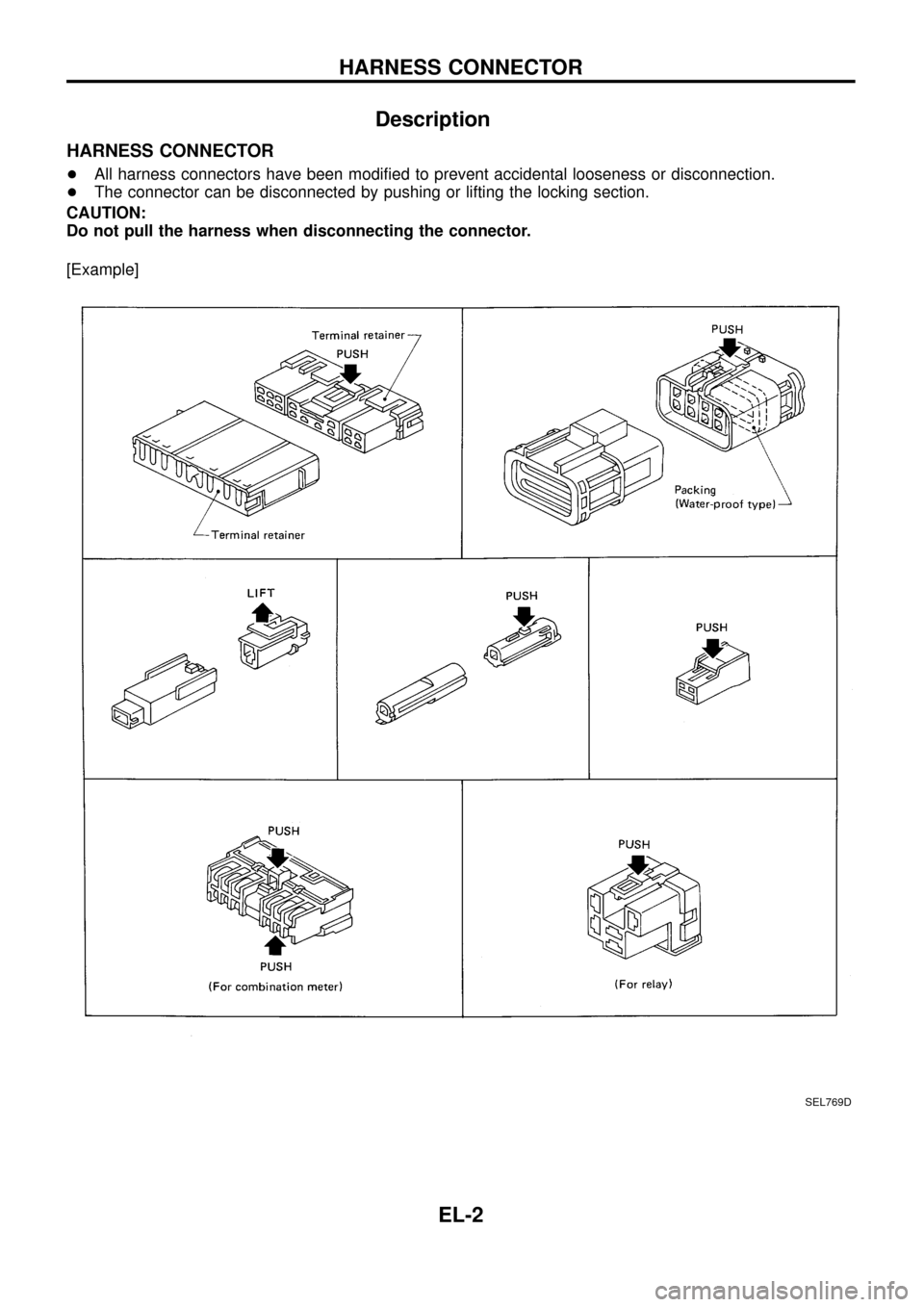
HARNESS CONNECTOR
+All harness connectors have been modi®ed to prevent accidental looseness or disconnection.
+The connector can be disconnected by pushing or lifting the locking section.
CAUTION:
Do not pull the harness when disconnecting the connector.
[Example]
SEL769D
HARNESS CONNECTOR
EL-2
Page 57 of 326
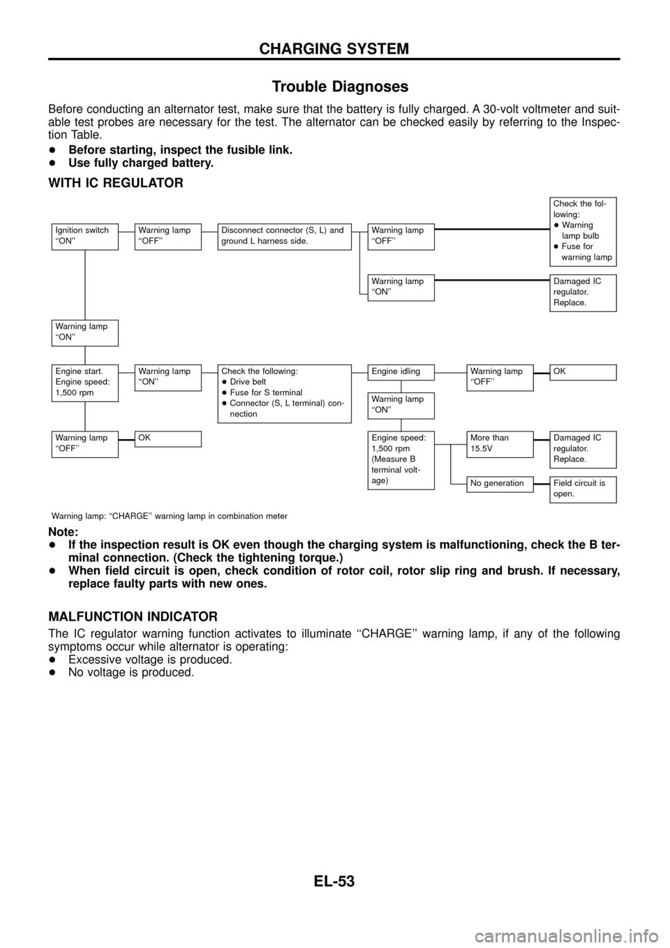
Trouble Diagnoses
Before conducting an alternator test, make sure that the battery is fully charged. A 30-volt voltmeter and suit-
able test probes are necessary for the test. The alternator can be checked easily by referring to the Inspec-
tion Table.
+Before starting, inspect the fusible link.
+Use fully charged battery.
WITH IC REGULATOR
Check the fol-
lowing:
+Warning
lamp bulb
+Fuse for
warning lamp
Ignition switch
``ON''Warning lamp
``OFF''Disconnect connector (S, L) and
ground L harness side.Warning lamp
``OFF''
Warning lamp
``ON''Damaged IC
regulator.
Replace.
Warning lamp
``ON''
Engine start.
Engine speed:
1,500 rpmWarning lamp
``ON''Check the following:
+Drive belt
+Fuse for S terminal
+Connector (S, L terminal) con-
nectionEngine idlingWarning lamp
``OFF''OK
Warning lamp
``ON''
Warning lamp
``OFF''OKEngine speed:
1,500 rpm
(Measure B
terminal volt-
age)More than
15.5VDamaged IC
regulator.
Replace.
No generationField circuit is
open.
Warning lamp: ``CHARGE'' warning lamp in combination meter
Note:
+If the inspection result is OK even though the charging system is malfunctioning, check the B ter-
minal connection. (Check the tightening torque.)
+When ®eld circuit is open, check condition of rotor coil, rotor slip ring and brush. If necessary,
replace faulty parts with new ones.
MALFUNCTION INDICATOR
The IC regulator warning function activates to illuminate ``CHARGE'' warning lamp, if any of the following
symptoms occur while alternator is operating:
+Excessive voltage is produced.
+No voltage is produced.
CHARGING SYSTEM
EL-53
Page 67 of 326
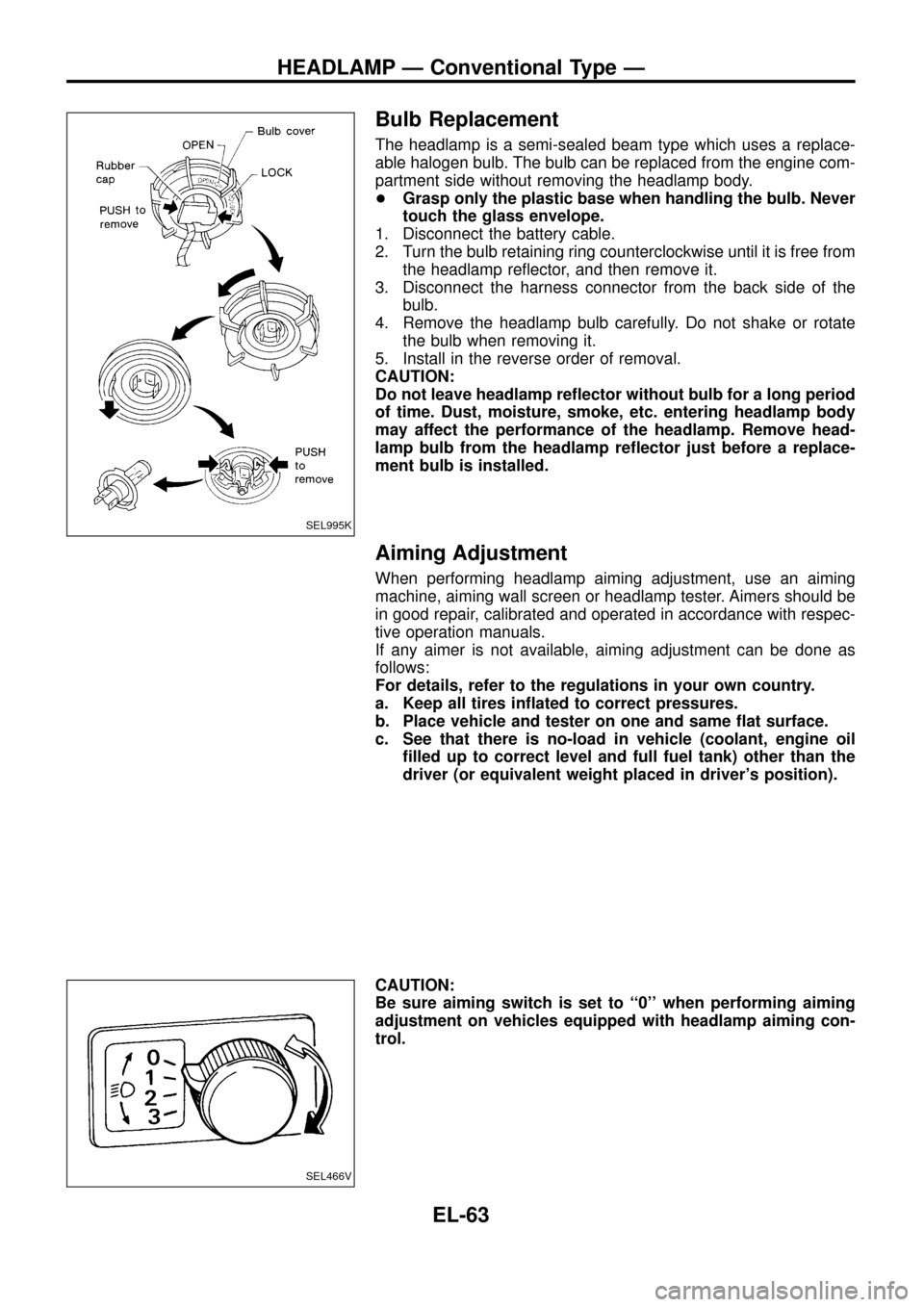
Bulb Replacement
The headlamp is a semi-sealed beam type which uses a replace-
able halogen bulb. The bulb can be replaced from the engine com-
partment side without removing the headlamp body.
+Grasp only the plastic base when handling the bulb. Never
touch the glass envelope.
1. Disconnect the battery cable.
2. Turn the bulb retaining ring counterclockwise until it is free from
the headlamp re¯ector, and then remove it.
3. Disconnect the harness connector from the back side of the
bulb.
4. Remove the headlamp bulb carefully. Do not shake or rotate
the bulb when removing it.
5. Install in the reverse order of removal.
CAUTION:
Do not leave headlamp re¯ector without bulb for a long period
of time. Dust, moisture, smoke, etc. entering headlamp body
may affect the performance of the headlamp. Remove head-
lamp bulb from the headlamp re¯ector just before a replace-
ment bulb is installed.
Aiming Adjustment
When performing headlamp aiming adjustment, use an aiming
machine, aiming wall screen or headlamp tester. Aimers should be
in good repair, calibrated and operated in accordance with respec-
tive operation manuals.
If any aimer is not available, aiming adjustment can be done as
follows:
For details, refer to the regulations in your own country.
a. Keep all tires in¯ated to correct pressures.
b. Place vehicle and tester on one and same ¯at surface.
c. See that there is no-load in vehicle (coolant, engine oil
®lled up to correct level and full fuel tank) other than the
driver (or equivalent weight placed in driver's position).
CAUTION:
Be sure aiming switch is set to ``0'' when performing aiming
adjustment on vehicles equipped with headlamp aiming con-
trol.
SEL995K
SEL466V
HEADLAMP Ð Conventional Type Ð
EL-63
Page 104 of 326
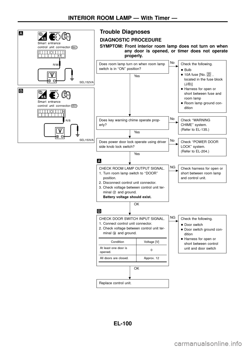
Trouble Diagnoses
DIAGNOSTIC PROCEDURE
SYMPTOM: Front interior room lamp does not turn on when
any door is opened, or timer does not operate
properly.
Does room lamp turn on when room lamp
switch is in ``ON'' position?
Ye s
cNo
Check the following.
+Bulb
+10A fuse [No.
20,
located in the fuse block
(J/B)]
+Harness for open or
short between fuse and
room lamp
+Room lamp ground con-
dition
Does key warning chime operate prop-
erly?
Ye s
cNo
Check ``WARNING
CHIME'' system.
(Refer to EL-135.)
Does power door lock operate using driver
side knob lock switch?
Ye s
cNo
Check ``POWER DOOR
LOCK'' system.
(Refer to EL-204.)
CHECK ROOM LAMP OUTPUT SIGNAL.
1. Turn room lamp switch to ``DOOR''
position.
2. Disconnect control unit connector.
3. Check voltage between control unit ter-
minalj
17and ground.
Battery voltage should exist.
OK
cNG
Check harness for open or
short between room lamp
and control unit.
CHECK DOOR SWITCH INPUT SIGNAL.
1. Connect control unit connector.
2. Check voltage between control unit ter-
minalj
10and ground.
OK
cNG
Check the following.
+Door switch
+Door switch ground con-
dition
+Harness for open or
short between control
unit and door switch
Replace control unit.
Condition Voltage [V]
At least one door is
opened.0
All doors are closed. Approx. 12
SEL152VA
SEL153VA
.
.
.
.
.
INTERIOR ROOM LAMP Ð With Timer Ð
EL-100
Page 113 of 326
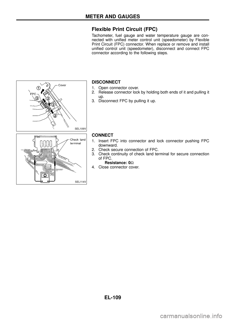
Flexible Print Circuit (FPC)
Tachometer, fuel gauge and water temperature gauge are con-
nected with uni®ed meter control unit (speedometer) by Flexible
Print Circuit (FPC) connector. When replace or remove and install
uni®ed control unit (speedometer), disconnect and connect FPC
connector according to the following steps.
DISCONNECT
1. Open connector cover.
2. Release connector lock by holding both ends of it and pulling it
up.
3. Disconnect FPC by pulling it up.
CONNECT
1. Insert FPC into connector and lock connector pushing FPC
downward.
2. Check secure connection of FPC.
3. Check continuity of check land terminal for secure connection
of FPC.
Resistance: 0W
4. Close connector cover.
SEL109V
SEL114V
METER AND GAUGES
EL-109