1998 NISSAN PATROL battery
[x] Cancel search: batteryPage 177 of 326
CATS (Code) System/RHD
NOTE:
+This system is used for code indicator-equipped radios on all models except the Europe LHD
model.
+The Europe LHD model has a NATS-linked anti-theft function that renders the code system inop-
erable.
DESCRIPTION
By using a personal 4-digit code known only to the vehicle owner, the possibility of the audio unit being sto-
len is effectively reduced, because without the code the unit can not be activated. When in normal use, the
unit is unlocked and accessible in the usual way.
If however, someone attempts to remove the unit or the battery cable is disconnected, the anti-theft system
activates and the unit ``locks''. The only way it can be unlocked is by entering a personal code number known
only by the owner.
UNLOCKING THE UNIT (How to enter a personal code number)
+If the battery supply to the vehicle is interrupted by accident for some reason, the unit will lock.
To unlock the unit, proceed as follows:
1. Press the power/volume control knob to turn the unit on.
2. ``CODE IN'' is displayed.
3. Input your personal code by pressing the preset buttons (1 to 4).
4. Press the
button.
5. If the entered code number is correct, the radio turns on.
When the code is incorrect
1. If the entered code is incorrect, the unit becomes inoperable for 10 seconds for the ®rst three attempts,
then the code input mode is automatically set (``CODE IN'' is displayed).
2. If the code is incorrect the fourth time, the unit becomes inoperable for 60 minutes and ``
'' is displayed.
After 60 minutes, the code input mode is automatically set (``CODE IN'' is displayed).
NOTE:
If the above is repeated 17 times, the unit will lock and ``LOCKED'' is displayed.
3. After ``LOCKED'' is displayed, radio can be returned to the code input mode only within three attempts as
follows. (Only three attempts are allowed to unlock the unit.)
a. Press the power/volume control knob while pushing both the MOD and TA switches.
b. The unit then returns to the code input mode.
CAUTION:
If the third attempt is unsuccessful, the unit will lock permanently.
AUDIO
EL-173
Page 178 of 326
NATS Audio Link/LHD
DESCRIPTION
The link with the NATS IMMU implies that the radio can basically only be operated if connected to the match-
ing NATS IMMU to which the radio was initially ®tted on the production line.
Since radio operation is impossible after the link with the NATS is disrupted theft of the radio unit is basically
useless since special equipment is required to reset the radio.
Initialisation process for radios that are linked to the NATS IMMU
New radios will be delivered to the factories in the ``NEW'' state, i.e. ready to be linked with the vehicle's NATS.
When the radio in ``NEW'' state is ®rst switched on at the factory, it will start up communication with the vehi-
cle's immobiliser control unit (IMMU) and send a code (the ``Radio Code'') to the IMMU. The IMMU will then
store this code, which is unique to each radio, in its (permanent) memory.
Upon receipt of the code by the IMMU, the NATS will con®rm correct receipt of the radio code to the radio.
Hereafter, the radio will operate as normal.
During the initialisation process, ``NEW'' is displayed on the radio display. Normally though, communication
between Radio and IMMU takes such a short time (300 ms) that the radio seems to switch on directly with-
out showing ``NEW'' on its display.
Normal operation
Each time the radio is switched on afterwards, the radio code will be veri®ed between the radio unit and the
NATS before the radio becomes operational. During the code veri®cation process, ``WAIT'' is shown on the
radio display. Again, the communication takes such a short time (300 ms) that the radio seems to switch on
directly without showing ``WAIT'' on its display.
When the radio is locked
In case of a radio being linked with the vehicle's NATS (immobiliser system), disconnection of the link between
the radio and the IMMU will cause the radio to switch into the lock (``SECURE'') mode in which the radio unit
is fully inoperative. Hence, repair of the radio is basically impossible, unless the radio is reset to the ``NEW''
state for which special decoding equipment is required.
Both Blaupunkt and Clarion have provided their authorized service representatives with so called ``decoder
boxes'' which can bring the radio unit back to the ``NEW'' state, enabling the radio to be switched on after which
repair can be carried out. Subsequently, when the repaired radio is delivered to the ®nal user again, it will be
in the ``NEW'' state as to enable re-linking the radio to the vehicle's immobiliser system. As a result of the
above, repair of the radio can only be done by an authorized Blaupunkt or Clarion representative.
Note:
Radio manufacturer of Nissan Y61 models for Europe is ``Clarion''.
SERVICE PROCEDURE
Item Service procedure Description
Battery disconnection No additional action required. Ð
Radio needs repair Repair needs to be done by authorized represen-
tative of radio manufacturer since radio cannot
be operated unless it is reset to NEW state,
using special decoding equipment.Ð
Replacement of radio by new
partNo additional action required. Radio is delivered in NEW state.
Transferring radio to another
vehicle/replacement of radio
by an ``old'' partRadio needs to be reset to NEW state by autho-
rized representative of radio manufacturer.Ð
Replacement of IMMU by
new partNo additional action required. The new IMMU will be recognized by the radio
since a `blank' code is stored in the memory of
the IMMU. In case the radio recognizes this
`blank' code, it will request for input of the correct
CATS code after which the radio will switch back
to the initialisation process.
AUDIO
EL-174
Page 187 of 326
Trouble Diagnoses
POWER ANTENNA
Symptom Possible causes Repair order
Power antenna does not oper-
ate.1. 10A fuse
2. Radio signal
3. Grounds
E25andE40
1. Check 10A fuse (No.56, located in fuse and fusible link
box). Verify that battery positive voltage is present at termi-
nalj
1: LHD,j2: RHD of power antenna.
2. Turn ignition switch and radio ON. Verify that battery positive
voltage is present at terminalj
3: LHD,j1: RHD of power
antenna.
3. Check grounds
E25andE40.
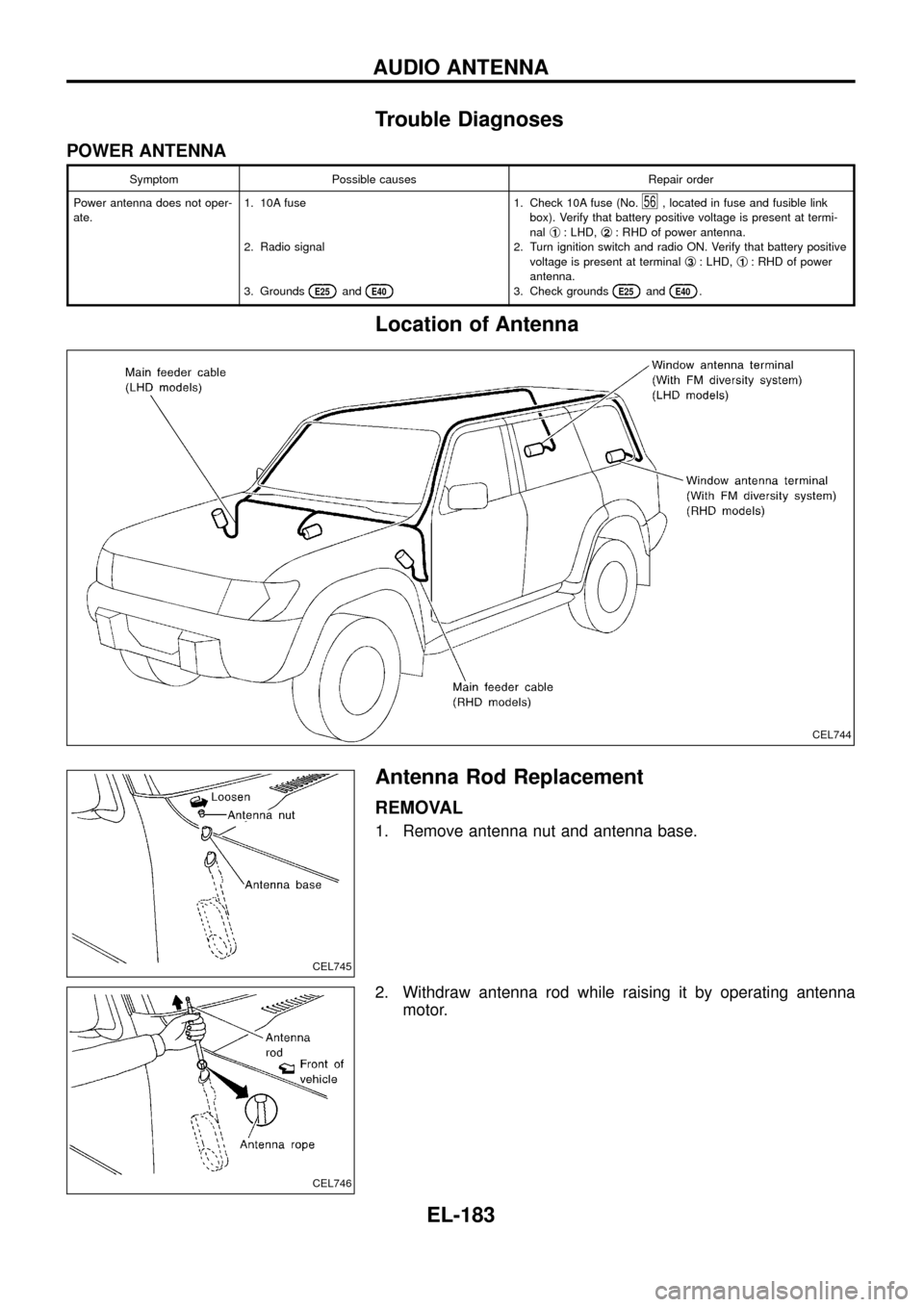
Location of Antenna
Antenna Rod Replacement
REMOVAL
1. Remove antenna nut and antenna base.
2. Withdraw antenna rod while raising it by operating antenna
motor.
CEL744
CEL745
CEL746
AUDIO ANTENNA
EL-183
Page 207 of 326
Trouble Diagnoses
Symptom Possible cause Repair order
None of the power windows can be
operated using any switch.1. 7.5A fuse, 40A fusible link and
M92circuit breaker
2. Grounds
M30andM19orM98
3. Power window relay
4. Open/short in power window
main switch circuit1. Check 7.5A fuse [No.
8, located in fuse block (J/B)],
40A fusible link (letter
e, located in fuse and fusible
link box) and
M92circuit breaker. Turn ignition switch
``ON'' and verify battery positive voltage is present at
terminalj
1of power window main switch and terminal
j
5of sub-switch.
2. Check grounds
M30andM19orM98.
3. Check power window relay.
4. Check W wire between power window relay and power
window main switch for open/short circuit.
Driver side power window cannot be
operated but other windows can be
operated.1. Driver side power window regula-
tor circuit
2. Driver side power window regula-
tor1. Check harness between power window main switch
and power window regulator for open or short circuit.
2. Check driver side power window regulator.
Passenger power window cannot be
operated.1. Power window sub-switches
2. Passenger side power window
regulators
3. Power window main switch
4. Power window circuit1. Check power window sub-switch.
2. Check passenger side power window regulator.
3. Check power window main switch.
4-1. Check harnesses between power window main
switch and power window sub-switch for open/
short circuit.
4-2. Check harnesses between power window sub-
switch and power window regulator for open/
short circuit.
Passenger power window cannot be
operated using power window main
switch but can be operated by power
window sub-switch.1. Power window main switch 1. Check power window main switch.
Driver side power window auto func-
tion cannot be operated using power
window main switch.1. Power window main switch 1. Check power window main switch.
POWER WINDOW
EL-203
Page 211 of 326
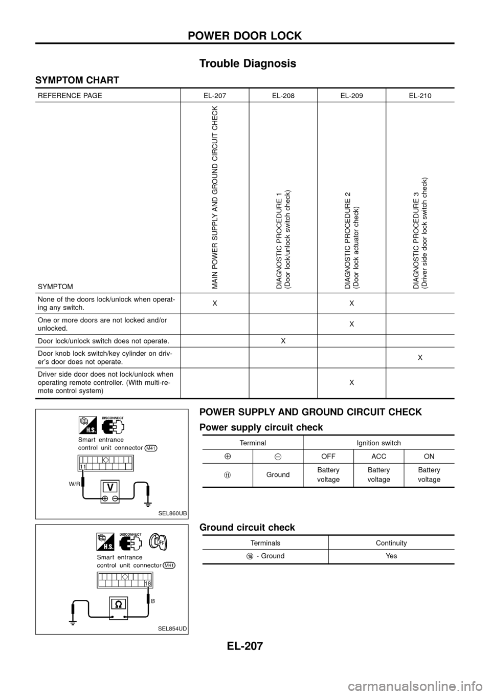
Trouble Diagnosis
SYMPTOM CHART
REFERENCE PAGE EL-207 EL-208 EL-209 EL-210
SYMPTOM
MAIN POWER SUPPLY AND GROUND CIRCUIT CHECK
DIAGNOSTIC PROCEDURE 1
(Door lock/unlock switch check)
DIAGNOSTIC PROCEDURE 2
(Door lock actuator check)
DIAGNOSTIC PROCEDURE 3
(Driver side door lock switch check)
None of the doors lock/unlock when operat-
ing any switch.XX
One or more doors are not locked and/or
unlocked.X
Door lock/unlock switch does not operate. X
Door knob lock switch/key cylinder on driv-
er's door does not operate.X
Driver side door does not lock/unlock when
operating remote controller. (With multi-re-
mote control system)X
POWER SUPPLY AND GROUND CIRCUIT CHECK
Power supply circuit check
Terminal Ignition switch
Å@OFF ACC ON
j
11GroundBattery
voltageBattery
voltageBattery
voltage
Ground circuit check
Terminals Continuity
j
18- Ground Yes
SEL860UB
SEL854UD
POWER DOOR LOCK
EL-207
Page 213 of 326
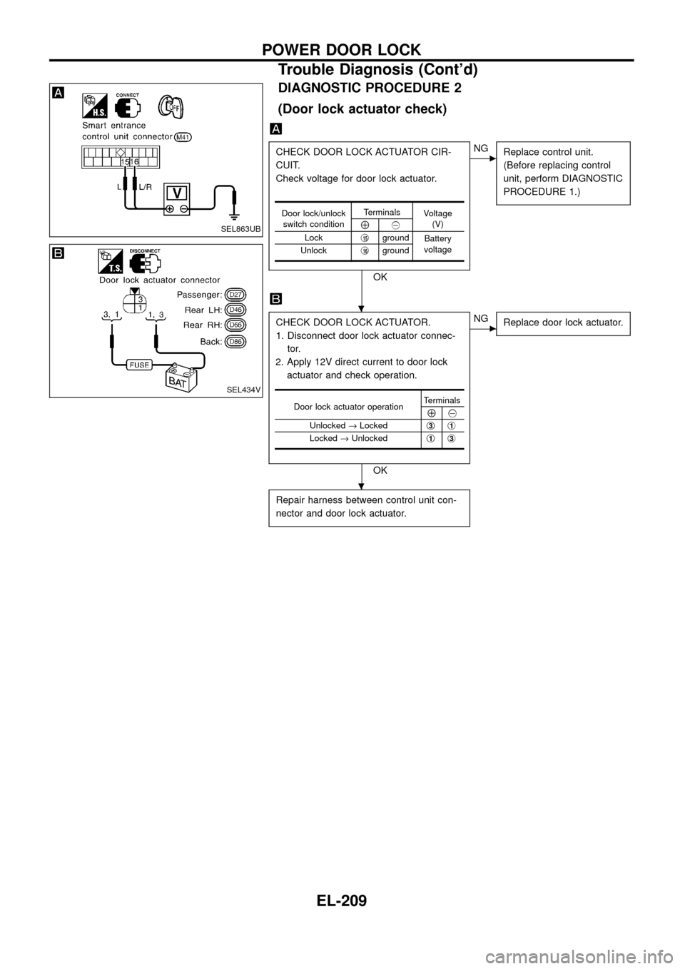
DIAGNOSTIC PROCEDURE 2
(Door lock actuator check)
CHECK DOOR LOCK ACTUATOR CIR-
CUIT.
Check voltage for door lock actuator.
OK
cNG
Replace control unit.
(Before replacing control
unit, perform DIAGNOSTIC
PROCEDURE 1.)
CHECK DOOR LOCK ACTUATOR.
1. Disconnect door lock actuator connec-
tor.
2. Apply 12V direct current to door lock
actuator and check operation.
OK
cNG
Replace door lock actuator.
Repair harness between control unit con-
nector and door lock actuator.
Door lock/unlock
switch conditionTerminals
Voltage
(V)
Å@
Lockj
15ground
Battery
voltage
Unlockj
16ground
Door lock actuator operationTerminalsÅ@
Unlocked®Lockedj
3j1
Locked®Unlockedj1j3
SEL863UB
SEL434V
.
.
POWER DOOR LOCK
Trouble Diagnosis (Cont'd)
EL-209
Page 217 of 326
Power door lock/unlock operation by lock knob
+With lock knob on driver or passenger door setting to LOCK while all doors are closed will lock all doors.
When one or more door is opened, with lock knob on passenger door setting to LOCK will lock
passenger door only. (Power door lock system will not operate.)
+With lock knob on driver or passenger door setting to UNLOCK while all doors are closed will unlock all
doors.
Lock knob operation cannot control super lock.
Key reminder system
+If the ignition key is in the ignition key cylinder and any door is open, setting lock/unlock switch or lock
knob on driver or passenger door to ``LOCK'' locks the door once but then immediately unlocks all doors.
System initialisation
+System initialisation is required when battery cables are reconnected. Conduct one of the followings to
release super lock once;
Ð insert the key into ignition key cylinder and turn it to ON.
Ð LOCK/UNLOCK operation using door key cylinder.
POWER DOOR LOCK Ð Super Lock Ð
System Description (Cont'd)
EL-213
Page 229 of 326
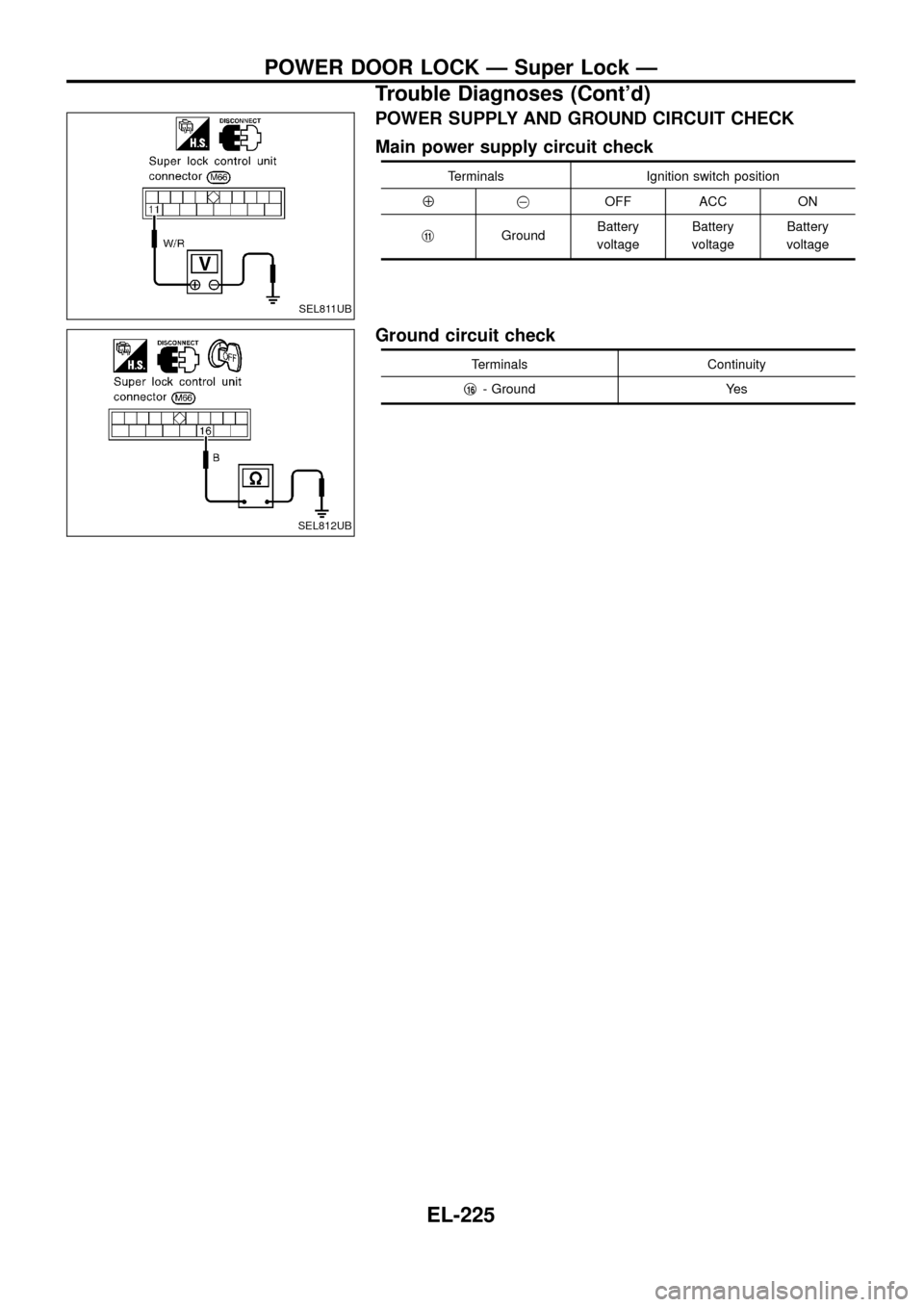
POWER SUPPLY AND GROUND CIRCUIT CHECK
Main power supply circuit check
Terminals Ignition switch position
Å@OFF ACC ON
j
11GroundBattery
voltageBattery
voltageBattery
voltage
Ground circuit check
Terminals Continuity
j
16- Ground Yes
SEL811UB
SEL812UB
POWER DOOR LOCK Ð Super Lock Ð
Trouble Diagnoses (Cont'd)
EL-225