Page 47 of 326
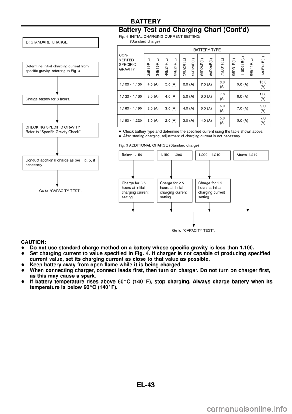
B: STANDARD CHARGE
Determine initial charging current from
speci®c gravity, referring to Fig. 4.
Charge battery for 8 hours.
CHECKING SPECIFIC GRAVITY
Refer to ``Speci®c Gravity Check''.
Conduct additional charge as per Fig. 5, if
necessary.
Go to ``CAPACITY TEST''.Fig. 4 INITIAL CHARGING CURRENT SETTING
(Standard charge)
CON-
VERTED
SPECIFIC
GRAVITYBATTERY TYPE
28B19R(L)
34B19R(L)
46B24R(L)
55B24R(L)
50D23R(L)
55D23R(L)
65D26R(L)
80D26R(L)
75D31R(L)
95D31R(L)
115D31R(L)
95E41R(L)
130E41R(L)
1.100 - 1.130 4.0 (A) 5.0 (A) 6.0 (A) 7.0 (A)8.0
(A)9.0 (A)13.0
(A)
1.130 - 1.160 3.0 (A) 4.0 (A) 5.0 (A) 6.0 (A)7.0
(A)8.0 (A)11.0
(A)
1.160 - 1.190 2.0 (A) 3.0 (A) 4.0 (A) 5.0 (A)6.0
(A)7.0 (A)9.0
(A)
1.190 - 1.220 2.0 (A) 2.0 (A) 3.0 (A) 4.0 (A)5.0
(A)5.0 (A)7.0
(A)
+Check battery type and determine the speci®ed current using the table shown above.
+After starting charging, adjustment of charging current is not necessary.
Fig. 5 ADDITIONAL CHARGE (Standard charge)
Below 1.150
1.150 - 1.2001.200 - 1.240Above 1.240
Charge for 3.5
hours at initial
charging current
setting.Charge for 2.5
hours at initial
charging current
setting.Charge for 1.5
hours at initial
charging current
setting.
Go to ``CAPACITY TEST''.
.
CAUTION:
+Do not use standard charge method on a battery whose speci®c gravity is less than 1.100.
+Set charging current to value speci®ed in Fig. 4. If charger is not capable of producing speci®ed
current value, set its charging current as close to that value as possible.
+Keep battery away from open ¯ame while it is being charged.
+When connecting charger, connect leads ®rst, then turn on charger. Do not turn on charger ®rst,
as this may cause a spark.
+If battery temperature rises above 60ÉC (140ÉF), stop charging. Always charge battery when its
temperature is below 60ÉC (140ÉF).
.
.
.
.
...
....
BATTERY
Battery Test and Charging Chart (Cont'd)
EL-43
Page 48 of 326
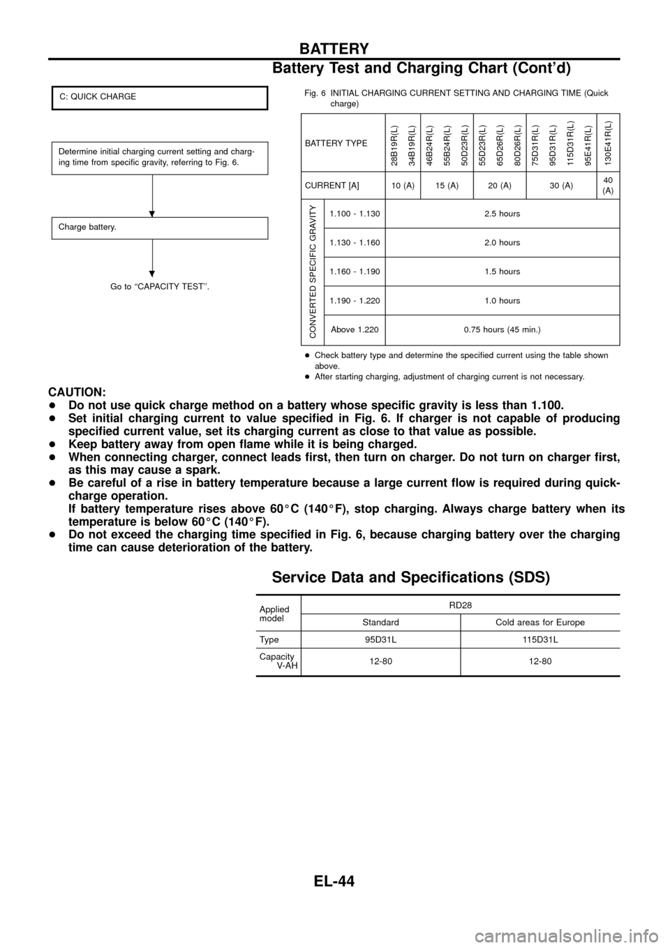
C: QUICK CHARGE
Determine initial charging current setting and charg-
ing time from speci®c gravity, referring to Fig. 6.
Charge battery.
Go to ``CAPACITY TEST''.Fig. 6 INITIAL CHARGING CURRENT SETTING AND CHARGING TIME (Quick
charge)
BATTERY TYPE
28B19R(L)
34B19R(L)
46B24R(L)
55B24R(L)
50D23R(L)
55D23R(L)
65D26R(L)
80D26R(L)
75D31R(L)
95D31R(L)
115D31R(L)
95E41R(L)
130E41R(L)
CURRENT [A] 10 (A) 15 (A) 20 (A) 30 (A)40
(A)
CONVERTED SPECIFIC GRAVITY
1.100 - 1.130 2.5 hours
1.130 - 1.160 2.0 hours
1.160 - 1.190 1.5 hours
1.190 - 1.220 1.0 hours
Above 1.220 0.75 hours (45 min.)
+Check battery type and determine the speci®ed current using the table shown
above.
+After starting charging, adjustment of charging current is not necessary.
CAUTION:
+Do not use quick charge method on a battery whose speci®c gravity is less than 1.100.
+Set initial charging current to value speci®ed in Fig. 6. If charger is not capable of producing
speci®ed current value, set its charging current as close to that value as possible.
+Keep battery away from open ¯ame while it is being charged.
+When connecting charger, connect leads ®rst, then turn on charger. Do not turn on charger ®rst,
as this may cause a spark.
+Be careful of a rise in battery temperature because a large current ¯ow is required during quick-
charge operation.
If battery temperature rises above 60ÉC (140ÉF), stop charging. Always charge battery when its
temperature is below 60ÉC (140ÉF).
+Do not exceed the charging time speci®ed in Fig. 6, because charging battery over the charging
time can cause deterioration of the battery.
Service Data and Speci®cations (SDS)
Applied
modelRD28
Standard Cold areas for Europe
Type 95D31L 115D31L
Capacity
V-AH12-80 12-80
.
.
BATTERY
Battery Test and Charging Chart (Cont'd)
EL-44
Page 50 of 326
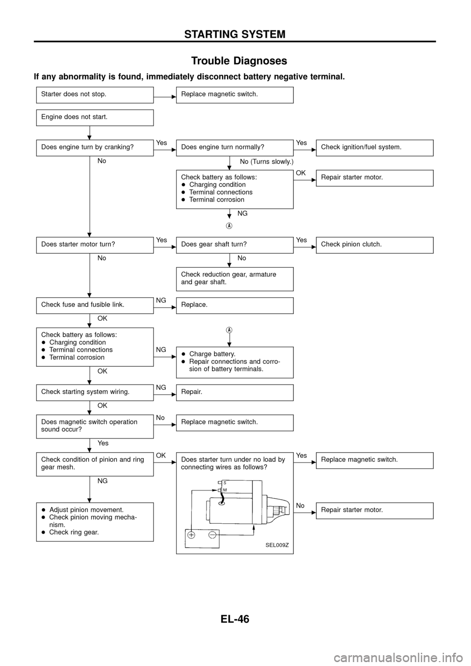
Trouble Diagnoses
If any abnormality is found, immediately disconnect battery negative terminal.
Starter does not stop.cReplace magnetic switch.
Engine does not start.
Does engine turn by cranking?
No
cYe s
Does engine turn normally?
No (Turns slowly.)
cYe s
Check ignition/fuel system.
Check battery as follows:
+Charging condition
+Terminal connections
+Terminal corrosion
NG
cOK
Repair starter motor.
jA
Does starter motor turn?
No
cYe s
Does gear shaft turn?
No
cYe s
Check pinion clutch.
Check reduction gear, armature
and gear shaft.
Check fuse and fusible link.
OK
cNG
Replace.
Check battery as follows:
+Charging condition
+Terminal connections
+Terminal corrosion
OKj
A
cNG
+Charge battery.
+Repair connections and corro-
sion of battery terminals.
Check starting system wiring.
OK
cNG
Repair.
Does magnetic switch operation
sound occur?
Ye s
cNo
Replace magnetic switch.
Check condition of pinion and ring
gear mesh.
NG
cOK
Does starter turn under no load by
connecting wires as follows?
SEL009Z
cYe s
Replace magnetic switch.
+Adjust pinion movement.
+Check pinion moving mecha-
nism.
+Check ring gear.cNo
Repair starter motor.
.
.
.
.
.
.
.
.
.
.
.
.
STARTING SYSTEM
EL-46
Page 51 of 326
Construction
Removal and Installation
Inspection
MAGNETIC SWITCH CHECK
+Before starting to check, disconnect battery ground cable.
+Disconnect ``M'' terminal of starter motor.
1. Continuity test (between ``S'' terminal and switch body).
+No continuity ... Replace.
MEL996DB
MEL609I
SEL036H
STARTING SYSTEM
EL-47
Page 57 of 326
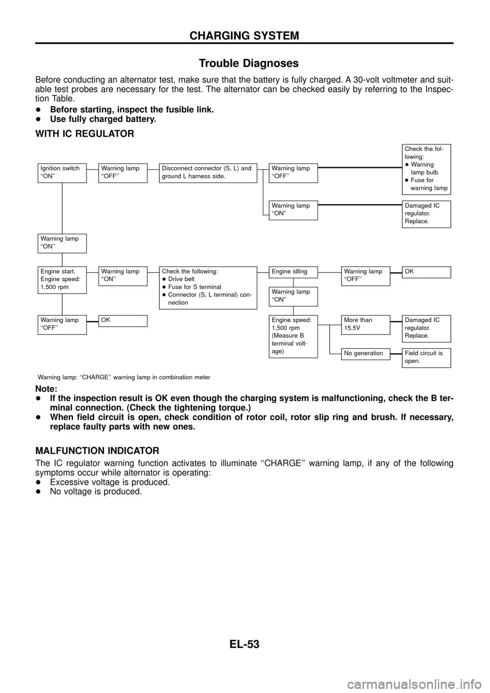
Trouble Diagnoses
Before conducting an alternator test, make sure that the battery is fully charged. A 30-volt voltmeter and suit-
able test probes are necessary for the test. The alternator can be checked easily by referring to the Inspec-
tion Table.
+Before starting, inspect the fusible link.
+Use fully charged battery.
WITH IC REGULATOR
Check the fol-
lowing:
+Warning
lamp bulb
+Fuse for
warning lamp
Ignition switch
``ON''Warning lamp
``OFF''Disconnect connector (S, L) and
ground L harness side.Warning lamp
``OFF''
Warning lamp
``ON''Damaged IC
regulator.
Replace.
Warning lamp
``ON''
Engine start.
Engine speed:
1,500 rpmWarning lamp
``ON''Check the following:
+Drive belt
+Fuse for S terminal
+Connector (S, L terminal) con-
nectionEngine idlingWarning lamp
``OFF''OK
Warning lamp
``ON''
Warning lamp
``OFF''OKEngine speed:
1,500 rpm
(Measure B
terminal volt-
age)More than
15.5VDamaged IC
regulator.
Replace.
No generationField circuit is
open.
Warning lamp: ``CHARGE'' warning lamp in combination meter
Note:
+If the inspection result is OK even though the charging system is malfunctioning, check the B ter-
minal connection. (Check the tightening torque.)
+When ®eld circuit is open, check condition of rotor coil, rotor slip ring and brush. If necessary,
replace faulty parts with new ones.
MALFUNCTION INDICATOR
The IC regulator warning function activates to illuminate ``CHARGE'' warning lamp, if any of the following
symptoms occur while alternator is operating:
+Excessive voltage is produced.
+No voltage is produced.
CHARGING SYSTEM
EL-53
Page 58 of 326
Construction
Removal and Installation
CAUTION:
+Start service operation after removing the negative termi-
nal from the battery.
+Also remove the undercover, if equipped, before servicing.
Disassembly
REAR COVER
CAUTION:
Rear cover may be hard to remove because a ring is used to
lock outer race of rear bearing. To facilitate removal of rear
cover, heat just bearing box section with a 200W soldering
iron.
Do not use a heat gun, as it can damage diode assembly.
YEL783A
MEL610I
SEL032Z
CHARGING SYSTEM
EL-54
Page 66 of 326
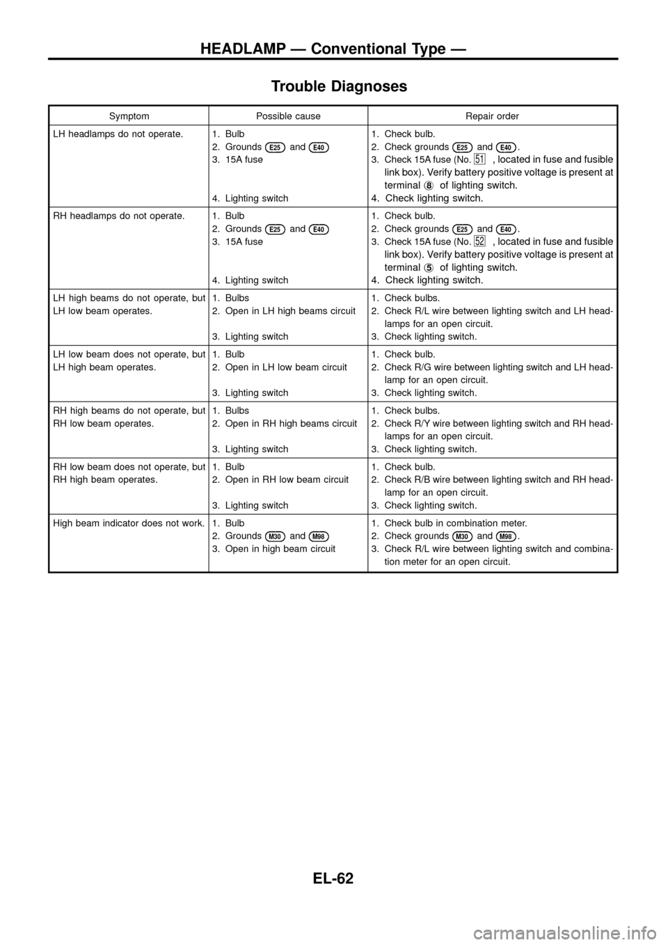
Trouble Diagnoses
Symptom Possible cause Repair order
LH headlamps do not operate. 1. Bulb
2. Grounds
E25andE40
3. 15A fuse
4. Lighting switch1. Check bulb.
2. Check grounds
E25andE40.
3. Check 15A fuse (No.
51, located in fuse and fusible
link box). Verify battery positive voltage is present at
terminalj
8of lighting switch.
4. Check lighting switch.
RH headlamps do not operate. 1. Bulb
2. Grounds
E25andE40
3. 15A fuse
4. Lighting switch1. Check bulb.
2. Check grounds
E25andE40.
3. Check 15A fuse (No.
52, located in fuse and fusible
link box). Verify battery positive voltage is present at
terminalj
5of lighting switch.
4. Check lighting switch.
LH high beams do not operate, but
LH low beam operates.1. Bulbs
2. Open in LH high beams circuit
3. Lighting switch1. Check bulbs.
2. Check R/L wire between lighting switch and LH head-
lamps for an open circuit.
3. Check lighting switch.
LH low beam does not operate, but
LH high beam operates.1. Bulb
2. Open in LH low beam circuit
3. Lighting switch1. Check bulb.
2. Check R/G wire between lighting switch and LH head-
lamp for an open circuit.
3. Check lighting switch.
RH high beams do not operate, but
RH low beam operates.1. Bulbs
2. Open in RH high beams circuit
3. Lighting switch1. Check bulbs.
2. Check R/Y wire between lighting switch and RH head-
lamps for an open circuit.
3. Check lighting switch.
RH low beam does not operate, but
RH high beam operates.1. Bulb
2. Open in RH low beam circuit
3. Lighting switch1. Check bulb.
2. Check R/B wire between lighting switch and RH head-
lamp for an open circuit.
3. Check lighting switch.
High beam indicator does not work. 1. Bulb
2. Grounds
M30andM98
3. Open in high beam circuit1. Check bulb in combination meter.
2. Check grounds
M30andM98.
3. Check R/L wire between lighting switch and combina-
tion meter for an open circuit.
HEADLAMP Ð Conventional Type Ð
EL-62
Page 67 of 326
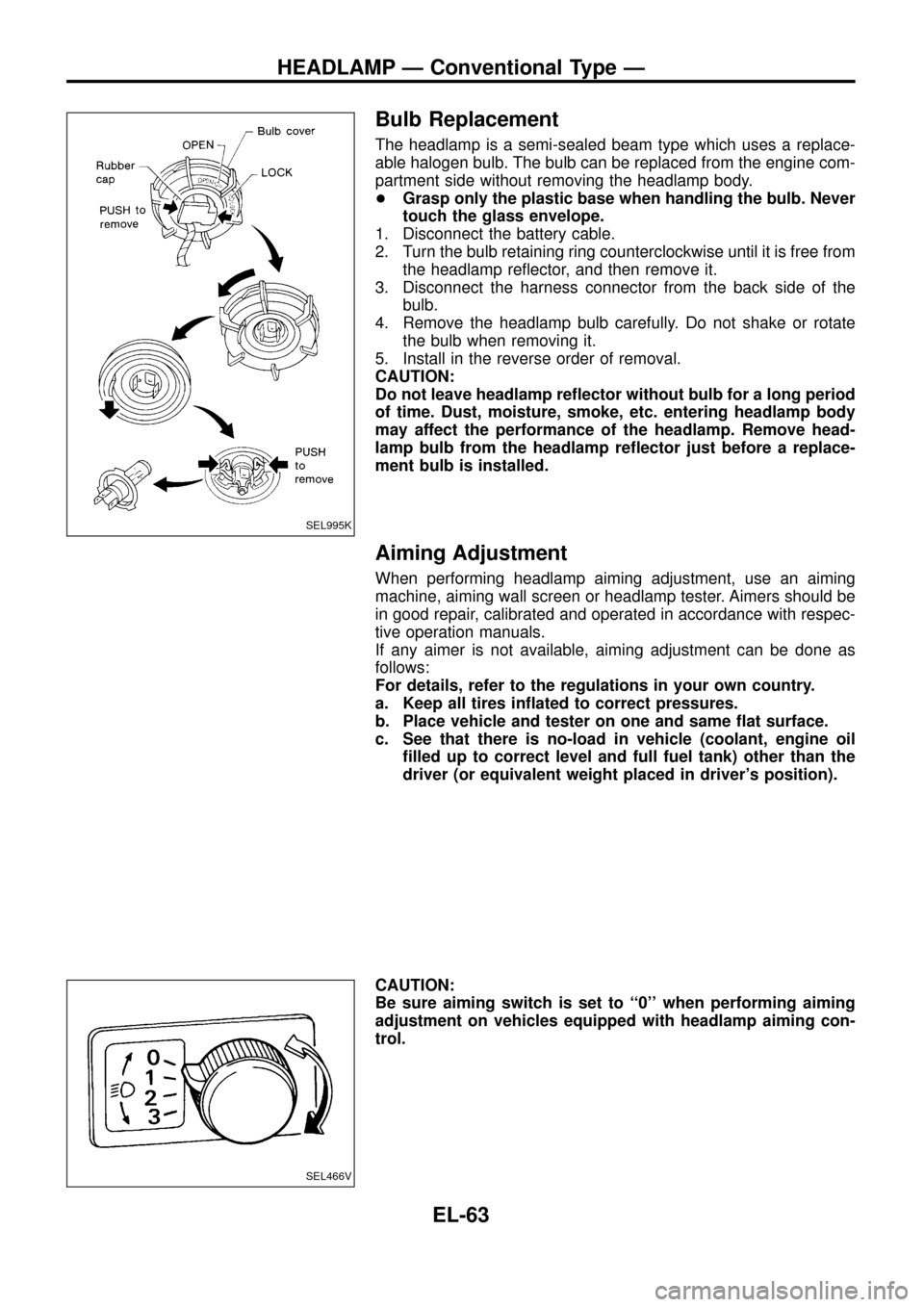
Bulb Replacement
The headlamp is a semi-sealed beam type which uses a replace-
able halogen bulb. The bulb can be replaced from the engine com-
partment side without removing the headlamp body.
+Grasp only the plastic base when handling the bulb. Never
touch the glass envelope.
1. Disconnect the battery cable.
2. Turn the bulb retaining ring counterclockwise until it is free from
the headlamp re¯ector, and then remove it.
3. Disconnect the harness connector from the back side of the
bulb.
4. Remove the headlamp bulb carefully. Do not shake or rotate
the bulb when removing it.
5. Install in the reverse order of removal.
CAUTION:
Do not leave headlamp re¯ector without bulb for a long period
of time. Dust, moisture, smoke, etc. entering headlamp body
may affect the performance of the headlamp. Remove head-
lamp bulb from the headlamp re¯ector just before a replace-
ment bulb is installed.
Aiming Adjustment
When performing headlamp aiming adjustment, use an aiming
machine, aiming wall screen or headlamp tester. Aimers should be
in good repair, calibrated and operated in accordance with respec-
tive operation manuals.
If any aimer is not available, aiming adjustment can be done as
follows:
For details, refer to the regulations in your own country.
a. Keep all tires in¯ated to correct pressures.
b. Place vehicle and tester on one and same ¯at surface.
c. See that there is no-load in vehicle (coolant, engine oil
®lled up to correct level and full fuel tank) other than the
driver (or equivalent weight placed in driver's position).
CAUTION:
Be sure aiming switch is set to ``0'' when performing aiming
adjustment on vehicles equipped with headlamp aiming con-
trol.
SEL995K
SEL466V
HEADLAMP Ð Conventional Type Ð
EL-63