1998 NISSAN PATROL Tail lamp
[x] Cancel search: Tail lampPage 2 of 326
Wiring Diagram Ð H/AIM Ð .....................................71
PARKING, LICENSE AND TAIL LAMPS......................73
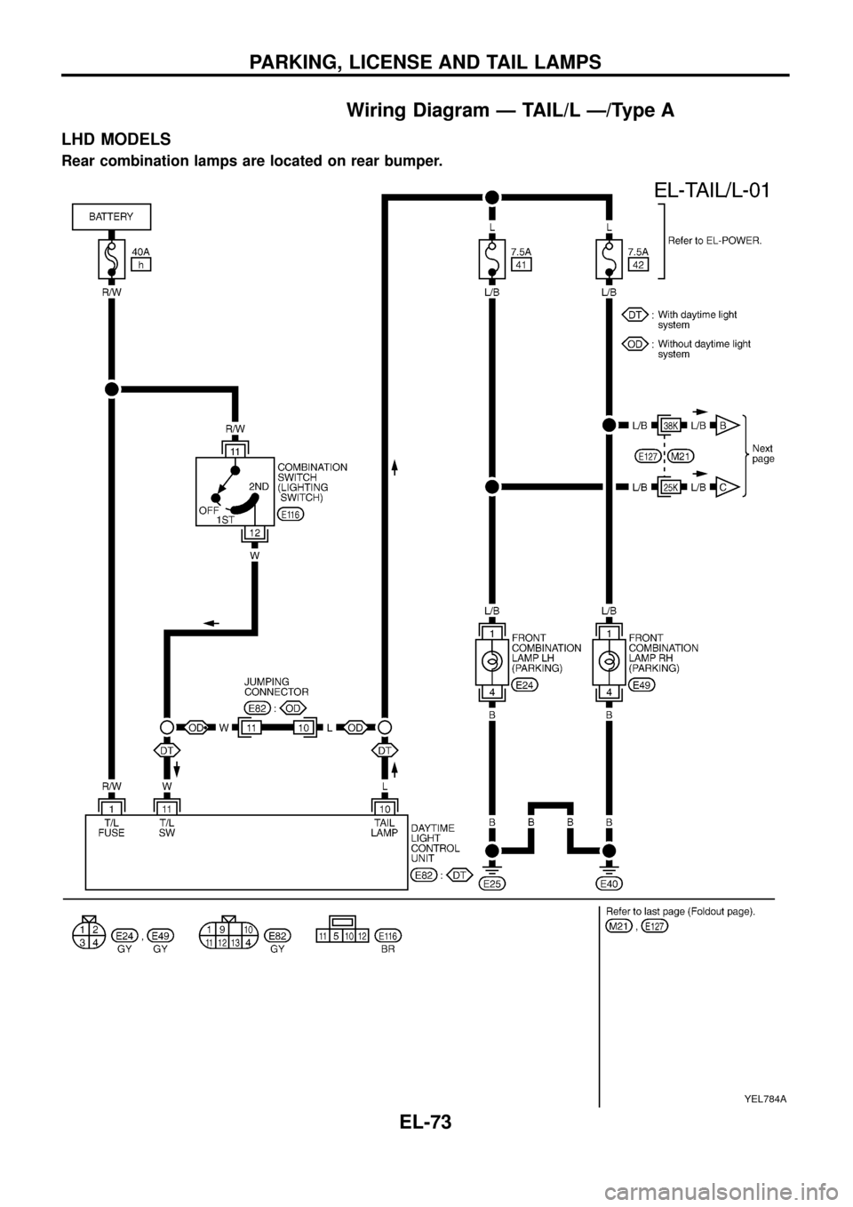
Wiring Diagram Ð TAIL/L Ð/Type A .........................73
Wiring Diagram Ð TAIL/L Ð/Type B.........................75
STOP LAMP..................................................................77
Wiring Diagram Ð STOP/L Ð/Type A ......................77
BACK-UP LAMP............................................................78
Wiring Diagram Ð BACK/L Ð/LHD Models..............78
Wiring Diagram Ð BACK/L Ð/RHD Models .............79
REAR FOG LAMP.........................................................80
Wiring Diagram Ð R/FOG Ð ....................................80
TURN SIGNAL AND HAZARD WARNING LAMPS.....81
Wiring Diagram Ð TURN Ð/Type A .........................81
Wiring Diagram Ð TURN Ð/Type B .........................83
Trouble Diagnoses.....................................................85
Electrical Components Inspection .............................85
ILLUMINATION..............................................................86
Schematic ..................................................................86
Wiring Diagram Ð ILL Ð ..........................................87
INTERIOR ROOM LAMP Ð With Timer Ð.................93
System Description ....................................................93
Schematic ..................................................................94
Wiring Diagram Ð ROOM/L Ð/LHD Models ............95
Wiring Diagram Ð ROOM/L Ð/RHD Models............98
Trouble Diagnoses...................................................100
MAP AND VANITY MIRROR LAMPS.........................101
Wiring Diagram Ð INT/L Ð.....................................101
METER AND GAUGES...............................................102
System Description ..................................................102
Combination Meter ..................................................103
Wiring Diagram Ð METER Ð/LHD Models............104
Wiring Diagram Ð METER Ð/RHD Models ...........106
Meter/Gauge Operation and Odo/Trip Meter
Segment Check in Diagnosis Mode ........................108
Flexible Print Circuit (FPC) ......................................109
Trouble Diagnoses................................................... 110
Electrical Components Inspection ........................... 114
COMPASS AND THERMOMETER............................. 116
System Description .................................................. 116
Wiring Diagram Ð COMPAS Ð .............................. 117
Trouble Diagnoses................................................... 118
Calibration Procedure For Compass ....................... 119
WARNING LAMPS......................................................121
Schematic ................................................................121
Wiring Diagram Ð WARN Ð ..................................123
Electrical Components Inspection ...........................134
WARNING CHIME.......................................................135
System Description ..................................................135
Wiring Diagram Ð CHIME Ð/LHD Models.............136
Wiring Diagram Ð CHIME Ð/RHD Models ............137
Trouble Diagnoses...................................................138
Electrical Components Inspection ...........................140FRONT WIPER AND WASHER..................................141
System Description ..................................................141
Wiring Diagram Ð WIPER Ð/With Intermittent
Wiper........................................................................142
Removal and Installation .........................................143
Washer Nozzle Adjustment .....................................144
Washer Tube Layout ...............................................144
REAR WIPER AND WASHER....................................145
System Description ..................................................145
Wiring Diagram Ð WIP/R Ð/LHD Models ..............146
Wiring Diagram Ð WIP/R Ð/RHD Models .............148
Trouble Diagnoses...................................................150
Removal and Installation .........................................151
Washer Nozzle Adjustment .....................................151
Washer Tube Layout ...............................................152
Check Valve .............................................................152
HEADLAMP WIPER AND WASHER..........................153
Wiring Diagram Ð HLC Ð ......................................153
Electrical Components Inspection ...........................154
Removal and Installation .........................................154
Washer Tube Layout ...............................................154
Check Valve .............................................................154
HORN...........................................................................155
Wiring Diagram Ð HORN Ð...................................155
CIGARETTE LIGHTER................................................156
Wiring Diagram Ð CIGAR Ð ..................................156
CLOCK.........................................................................157
Wiring Diagram Ð CLOCK Ð .................................157
REAR WINDOW DEFOGGER.....................................158
System Description ..................................................158
Wiring Diagram Ð DEF Ð/LHD Models .................159
Wiring Diagram Ð DEF Ð/RHD Models ................161
Trouble Diagnoses...................................................163
Electrical Components Inspection ...........................164
Filament Check ........................................................164
Filament Repair .......................................................165
WIPER DEICER...........................................................166
System Description ..................................................166
Wiring Diagram Ð DEICER Ð................................167
AUDIO..........................................................................168
Wiring Diagram Ð AUDIO Ð/LHD Models .............168
Wiring Diagram Ð AUDIO Ð/RHD Models ............170
Trouble Diagnoses...................................................172
CATS (Code) System/RHD .....................................173
NATS Audio Link/LHD .............................................174
AUDIO Ð CD AUTO CHANGER Ð...........................176
Wiring Diagram Ð CD/CHG Ð/LHD Wagon ..........176
Wiring Diagram Ð CD/CHG Ð/LHD Hardtop .........177
Wiring Diagram Ð CD/CHG Ð/RHD Wagon ..........178
Wiring Diagram Ð CD/CHG Ð/RHD Hardtop ........179
Trouble Diagnoses...................................................180
AUDIO ANTENNA.......................................................181
Page 67 of 326
Bulb Replacement
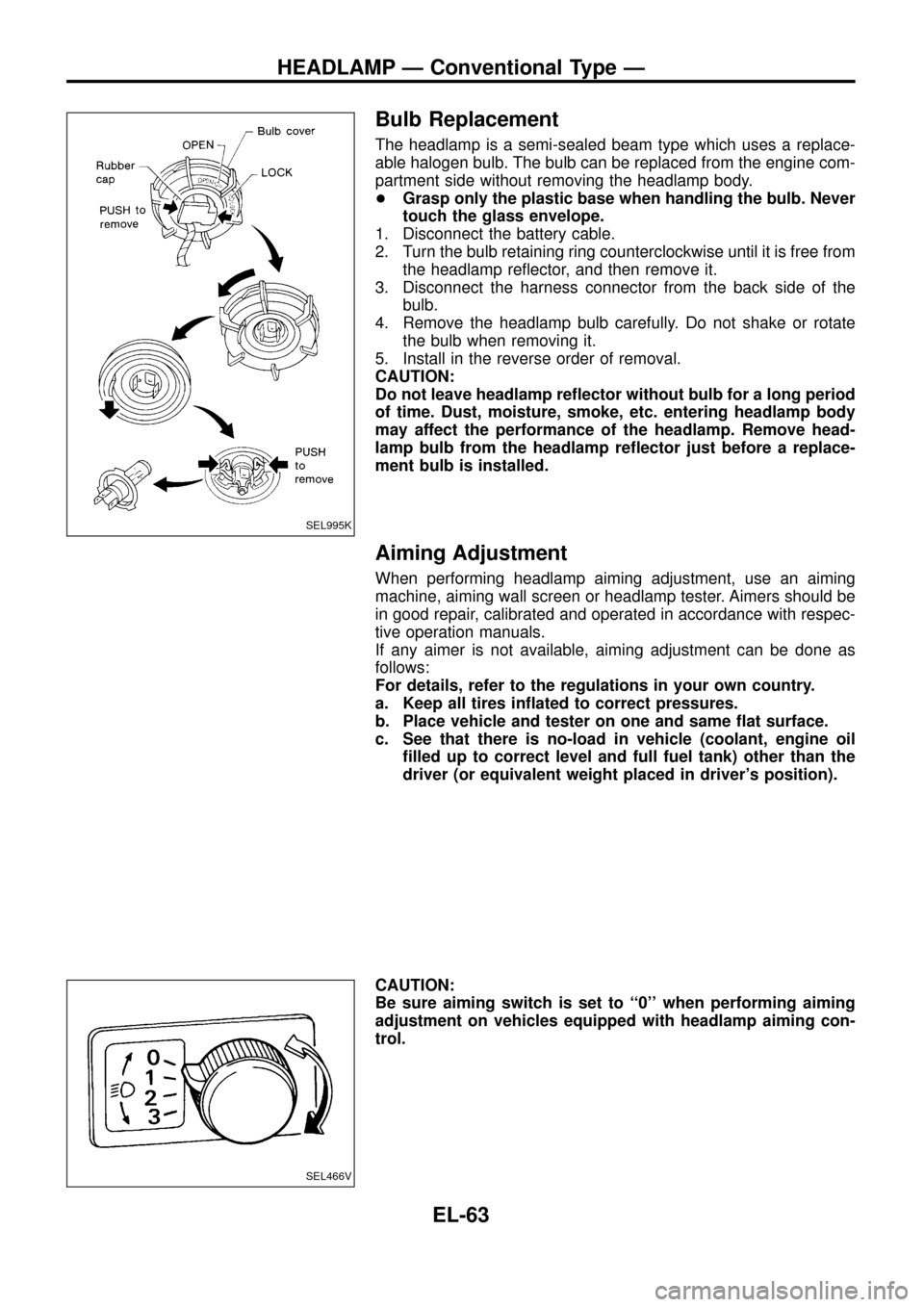
The headlamp is a semi-sealed beam type which uses a replace-
able halogen bulb. The bulb can be replaced from the engine com-
partment side without removing the headlamp body.
+Grasp only the plastic base when handling the bulb. Never
touch the glass envelope.
1. Disconnect the battery cable.
2. Turn the bulb retaining ring counterclockwise until it is free from
the headlamp re¯ector, and then remove it.
3. Disconnect the harness connector from the back side of the
bulb.
4. Remove the headlamp bulb carefully. Do not shake or rotate
the bulb when removing it.
5. Install in the reverse order of removal.
CAUTION:
Do not leave headlamp re¯ector without bulb for a long period
of time. Dust, moisture, smoke, etc. entering headlamp body
may affect the performance of the headlamp. Remove head-
lamp bulb from the headlamp re¯ector just before a replace-
ment bulb is installed.
Aiming Adjustment
When performing headlamp aiming adjustment, use an aiming
machine, aiming wall screen or headlamp tester. Aimers should be
in good repair, calibrated and operated in accordance with respec-
tive operation manuals.
If any aimer is not available, aiming adjustment can be done as
follows:
For details, refer to the regulations in your own country.
a. Keep all tires in¯ated to correct pressures.
b. Place vehicle and tester on one and same ¯at surface.
c. See that there is no-load in vehicle (coolant, engine oil
®lled up to correct level and full fuel tank) other than the
driver (or equivalent weight placed in driver's position).
CAUTION:
Be sure aiming switch is set to ``0'' when performing aiming
adjustment on vehicles equipped with headlamp aiming con-
trol.
SEL995K
SEL466V
HEADLAMP Ð Conventional Type Ð
EL-63
Page 69 of 326
System Description
OPERATION
Headlamp system on vehicles for North Europe contains a daytime light system. The unit operates to illumi-
nate headlamps low beam, parking, tail, license lamps and illuminations automatically in the following condi-
tions.
+The engine is running with lighting switch in OFF position.
When the any of following conditions exists, the daytime light operation will be canceled.
+Ignition switch is in any position other than ON
+Engine is stopped
+Lighting switch is turned to 1st or 2nd position.
If the daytime light system is canceled, lighting switch operations are the same as for conventional light sys-
tem.
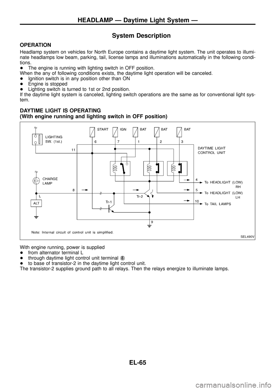
DAYTIME LIGHT IS OPERATING
(With engine running and lighting switch in OFF position)
With engine running, power is supplied
+from alternator terminal L
+through daytime light control unit terminalj
8
+to base of transistor-2 in the daytime light control unit.
The transistor-2 supplies ground path to all relays. Then the relays energize to illuminate lamps.
SEL490V
HEADLAMP Ð Daytime Light System Ð
EL-65
Page 73 of 326
Trouble Diagnoses
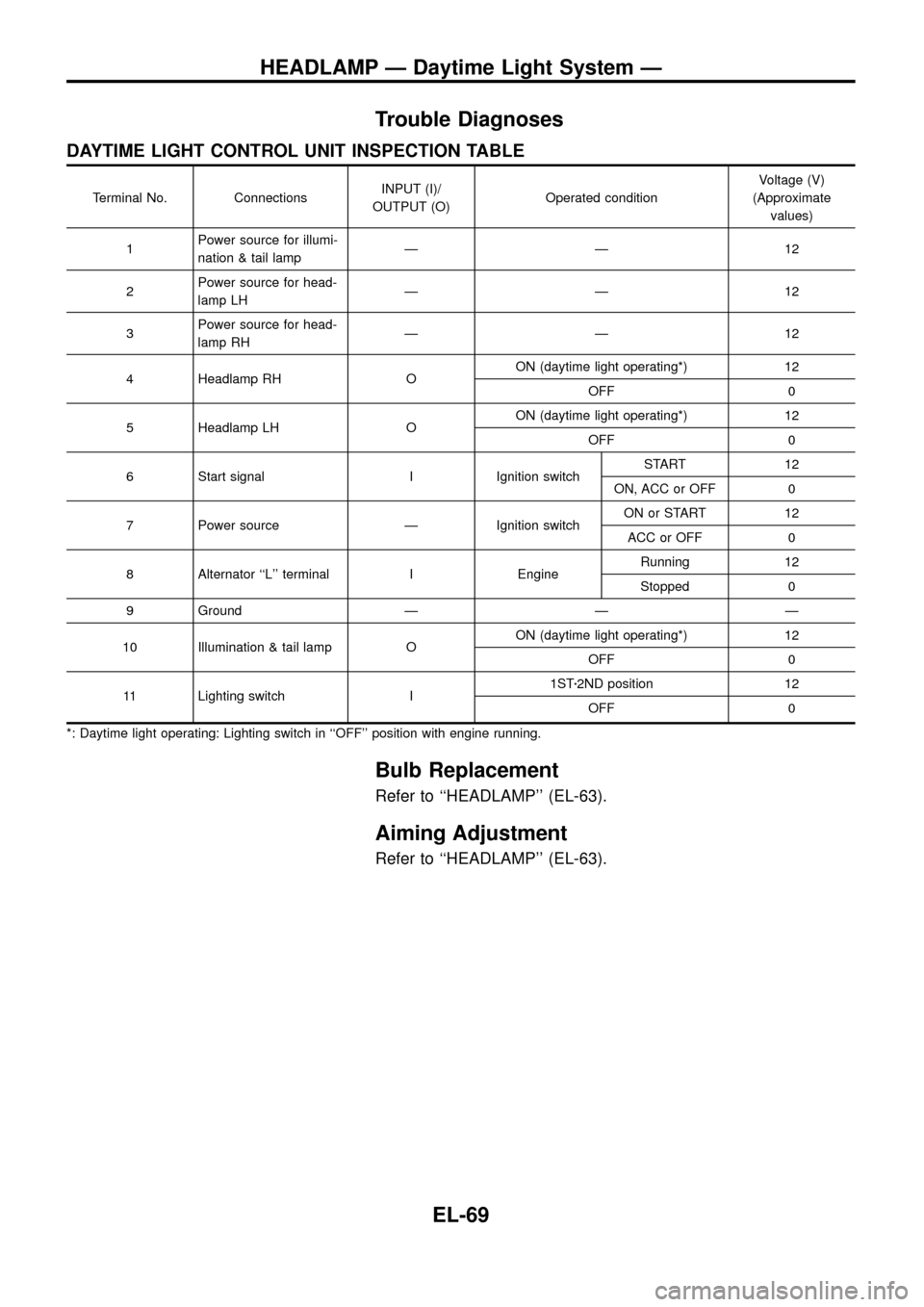
DAYTIME LIGHT CONTROL UNIT INSPECTION TABLE
Terminal No. ConnectionsINPUT (I)/
OUTPUT (O)Operated conditionVoltage (V)
(Approximate
values)
1Power source for illumi-
nation & tail lampÐÐ12
2Power source for head-
lamp LHÐÐ12
3Power source for head-
lamp RHÐÐ12
4 Headlamp RH OON (daytime light operating*) 12
OFF 0
5 Headlamp LH OON (daytime light operating*) 12
OFF 0
6 Start signal I Ignition switchSTART 12
ON, ACC or OFF 0
7 Power source Ð Ignition switchON or START 12
ACC or OFF 0
8 Alternator ``L'' terminal I EngineRunning 12
Stopped 0
9 Ground Ð Ð Ð
10 Illumination & tail lamp OON (daytime light operating*) 12
OFF 0
11 Lighting switch I1STz2ND position 12
OFF 0
*: Daytime light operating: Lighting switch in ``OFF'' position with engine running.
Bulb Replacement
Refer to ``HEADLAMP'' (EL-63).
Aiming Adjustment
Refer to ``HEADLAMP'' (EL-63).
HEADLAMP Ð Daytime Light System Ð
EL-69
Page 77 of 326
Wiring Diagram Ð TAIL/L Ð/Type A
LHD MODELS
Rear combination lamps are located on rear bumper.
YEL784A
PARKING, LICENSE AND TAIL LAMPS
EL-73
Page 78 of 326
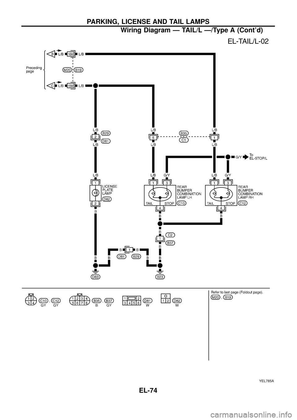
YEL785A
PARKING, LICENSE AND TAIL LAMPS
Wiring Diagram Ð TAIL/L Ð/Type A (Cont'd)
EL-74
Page 79 of 326
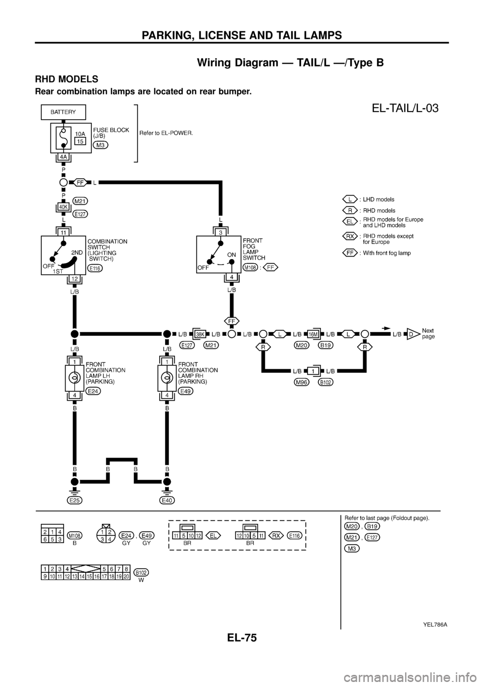
Wiring Diagram Ð TAIL/L Ð/Type B
RHD MODELS
Rear combination lamps are located on rear bumper.
YEL786A
PARKING, LICENSE AND TAIL LAMPS
EL-75
Page 80 of 326
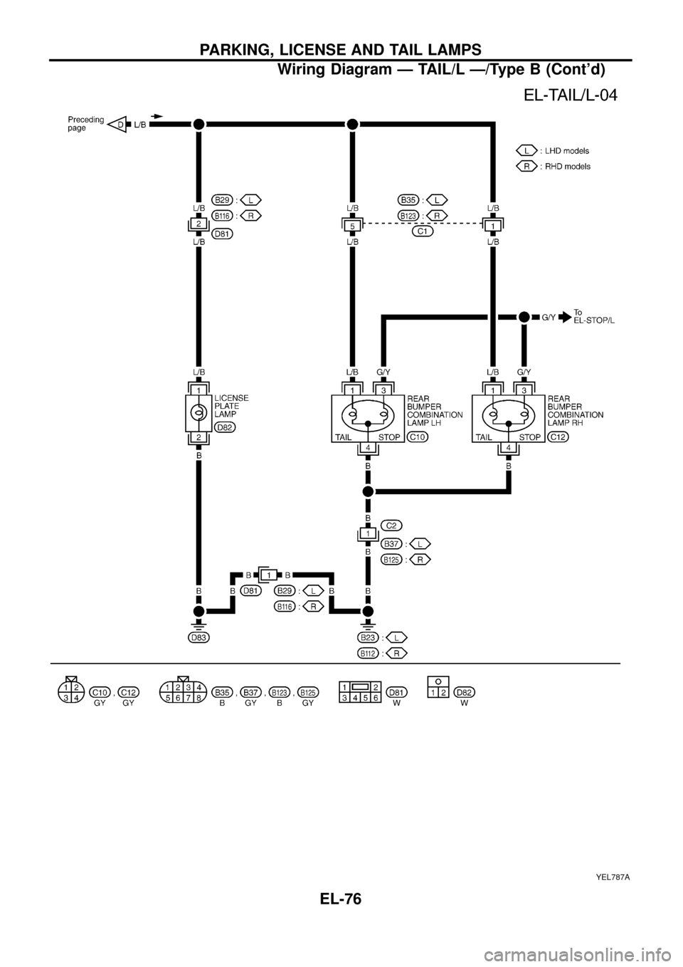
YEL787A
PARKING, LICENSE AND TAIL LAMPS
Wiring Diagram Ð TAIL/L Ð/Type B (Cont'd)
EL-76