Page 114 of 326

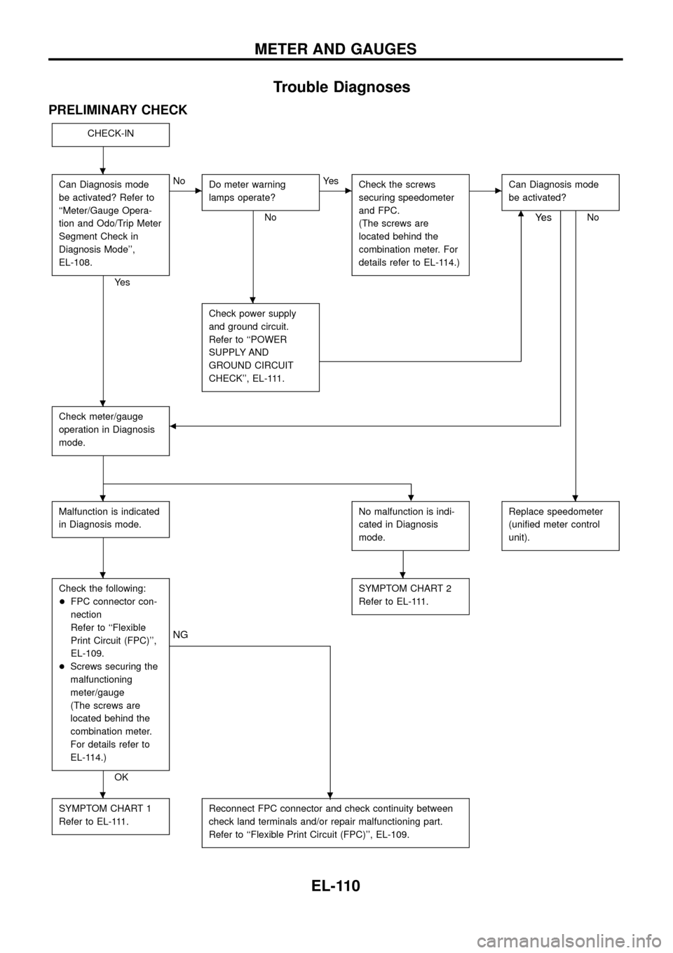
Trouble Diagnoses
PRELIMINARY CHECK
CHECK-IN
Can Diagnosis mode
be activated? Refer to
``Meter/Gauge Opera-
tion and Odo/Trip Meter
Segment Check in
Diagnosis Mode'',
EL-108.
Ye s
cNo
Do meter warning
lamps operate?
No
cYe s
Check the screws
securing speedometer
and FPC.
(The screws are
located behind the
combination meter. For
details refer to EL-114.)cCan Diagnosis mode
be activated?
Nom
Check power supply
and ground circuit.
Refer to ``POWER
SUPPLY AND
GROUND CIRCUIT
CHECK'', EL-111.
Check meter/gauge
operation in Diagnosis
mode.b
Ye s
.
Malfunction is indicated
in Diagnosis mode.No malfunction is indi-
cated in Diagnosis
mode.Replace speedometer
(uni®ed meter control
unit).
Check the following:
+FPC connector con-
nection
Refer to ``Flexible
Print Circuit (FPC)'',
EL-109.
+Screws securing the
malfunctioning
meter/gauge
(The screws are
located behind the
combination meter.
For details refer to
EL-114.)
OK
.
NG
SYMPTOM CHART 2
Refer to EL-111.
SYMPTOM CHART 1
Refer to EL-111.Reconnect FPC connector and check continuity between
check land terminals and/or repair malfunctioning part.
Refer to ``Flexible Print Circuit (FPC)'', EL-109.
.
.
.
..
..
.
METER AND GAUGES
EL-110
Page 238 of 326

System Description
FUNCTION
Multi-remote control system has the following function.
+Door lock (and set super lock)
+Door unlock (and release super lock)
+Hazard reminder
LOCK OPERATION
To lock door by multi-remote controller, the following two signals must be received.
+Key switch OFF (when ignition key is not in ignition key cylinder.)
+All door switches CLOSED
When the LOCK signal is input to multi-remote control unit (the antenna of the system is combined with multi-
remote control unit), ground is supplied
+through multi-remote control unit terminalj
10
+to super lock control unit terminalj2.
Then super lock control unit operates to lock doors and set super lock.
UNLOCK OPERATION
To unlock door by multi-remote controller, the following signal must be received.
+Key switch OFF (when ignition key is not in ignition key cylinder)
When the UNLOCK signal is input to multi-remote control unit (the antenna of the system is combined with
multi-remote control unit), ground is supplied
+through multi-remote control unit terminalj
11
+to super lock control unit terminalj3.
Then super lock control unit operates to unlock doors and release super lock.
HAZARD REMINDER
When the doors are locked or unlocked by multi-remote controller, ground is supplied
+to terminalj
1of multi-remote control relay-1 and 2
+through multi-remote control unit terminalj
12.
Then the relays are energized and hazard warning lamp ¯ashes as follows
+Lock operation: Flash once
+Unlock operation: Flash twice
MULTI-REMOTE CONTROLLER ID CODE ENTRY
A maximum of four remote controllers can be entered. Any attempt to enter a remote controller will erase all
ID codes previously entered. Therefore, be sure to receive all remote controllers from the vehicle owner when
any ID code entry is performed.
To enter ID code entry, the following signals must be input to the multi-remote control unit.
+Driver side LOCKED signal (from driver side door unlock sensor)
+Door switch CLOSED signal
+Key switch signal (INSERTED/WITHDRAWN)
+Accessory power supply
+Signal from remote controller
For detailed procedure, refer to ``ID Code Entry Procedure'' in EL-239.
MULTI-REMOTE CONTROL SYSTEM
EL-234
Page 318 of 326
Headlamp
Wattage (12 volt)
High/low (without xenon headlamp) 60/55 (H4)
Exterior Lamp
Wattage (12 volt)
Front combination lampFront turn signal 21
Parking 5
Side turn signal lamp 5
Rear combination lampTurn signal 21
Stop/Tail 21/5
Back-up 21
Fog 21
Rear bumper combina-
tion lampTurn signal 21
Stop/Tail 21/5
License plate lamp 5
High-mounted stop lamp 21
Interior Lamp
Wattage (12 volt)
Interior room lamp 10
Map lamp 10
Vanity mirror lamp 3
BULB SPECIFICATIONS
EL-314
Page 320 of 326
Code Section Wiring Diagram Name
STAB RARear Stabilizer Release Device Con-
trol System
START EL Starting System
STOP/L EL Stop Lamp
TAIL/L ELParking, License, Tail and Stop
Lamps
TCV EC Injection Timing Control Valve
TPS EC Throttle Position Sensor
TURN ELTurn Signal and Hazard Warning
Lamps
VSS EC Vehicle Speed Sensor
WARN EL Warning Lamps
WINCH SE Electrical Winch
WINDOW EL Power Window
WIP/R EL Rear Wiper and Washer
WIPER EL Front Wiper and Washer
WIRING DIAGRAM CODES (CELL CODES)
EL-316