1998 NISSAN PATROL Air condition
[x] Cancel search: Air conditionPage 4 of 326
BULB SPECIFICATIONS............................................314
Headlamp.................................................................314
Exterior Lamp ..........................................................314
Interior Lamp............................................................314
WIRING DIAGRAM CODES (CELL CODES) .............315
WIRING DIAGRAM REFERENCE CHART
ECCS, IGNITION SYSTEM ........................................................................\
................... EC SECTION
ANTI-LOCK BRAKE SYSTEM ........................................................................\
.............. BR SECTION
SRS ``AIR BAG'' ........................................................................\
.................................... RS SECT ION
HEATER AND AIR CONDITIONER ........................................................................\
...... HA SECTION
DIFFERENTIAL CARRIER ........................................................................\
.................... PD SECTION
REAR SUSPENSION ........................................................................\
............................. RA SECTION
FUEL SYSTEM ........................................................................\
....................................... FE SECT ION
Page 50 of 326
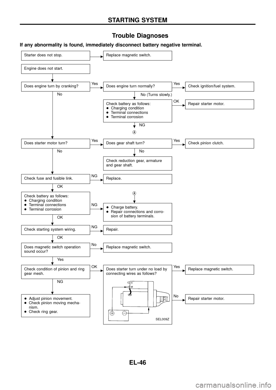
Trouble Diagnoses
If any abnormality is found, immediately disconnect battery negative terminal.
Starter does not stop.cReplace magnetic switch.
Engine does not start.
Does engine turn by cranking?
No
cYe s
Does engine turn normally?
No (Turns slowly.)
cYe s
Check ignition/fuel system.
Check battery as follows:
+Charging condition
+Terminal connections
+Terminal corrosion
NG
cOK
Repair starter motor.
jA
Does starter motor turn?
No
cYe s
Does gear shaft turn?
No
cYe s
Check pinion clutch.
Check reduction gear, armature
and gear shaft.
Check fuse and fusible link.
OK
cNG
Replace.
Check battery as follows:
+Charging condition
+Terminal connections
+Terminal corrosion
OKj
A
cNG
+Charge battery.
+Repair connections and corro-
sion of battery terminals.
Check starting system wiring.
OK
cNG
Repair.
Does magnetic switch operation
sound occur?
Ye s
cNo
Replace magnetic switch.
Check condition of pinion and ring
gear mesh.
NG
cOK
Does starter turn under no load by
connecting wires as follows?
SEL009Z
cYe s
Replace magnetic switch.
+Adjust pinion movement.
+Check pinion moving mecha-
nism.
+Check ring gear.cNo
Repair starter motor.
.
.
.
.
.
.
.
.
.
.
.
.
STARTING SYSTEM
EL-46
Page 120 of 326
System Description
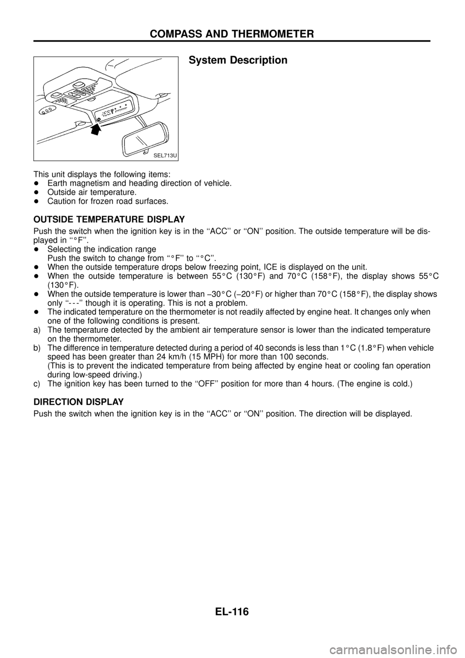
This unit displays the following items:
+Earth magnetism and heading direction of vehicle.
+Outside air temperature.
+Caution for frozen road surfaces.
OUTSIDE TEMPERATURE DISPLAY
Push the switch when the ignition key is in the ``ACC'' or ``ON'' position. The outside temperature will be dis-
played in ``ÉF''.
+Selecting the indication range
Push the switch to change from ``ÉF'' to ``ÉC''.
+When the outside temperature drops below freezing point, ICE is displayed on the unit.
+When the outside temperature is between 55ÉC (130ÉF) and 70ÉC (158ÉF), the display shows 55ÉC
(130ÉF).
+When the outside temperature is lower than þ30ÉC (þ20ÉF) or higher than 70ÉC (158ÉF), the display shows
only ``- - -'' though it is operating. This is not a problem.
+The indicated temperature on the thermometer is not readily affected by engine heat. It changes only when
one of the following conditions is present.
a) The temperature detected by the ambient air temperature sensor is lower than the indicated temperature
on the thermometer.
b) The difference in temperature detected during a period of 40 seconds is less than 1ÉC (1.8ÉF) when vehicle
speed has been greater than 24 km/h (15 MPH) for more than 100 seconds.
(This is to prevent the indicated temperature from being affected by engine heat or cooling fan operation
during low-speed driving.)
c) The ignition key has been turned to the ``OFF'' position for more than 4 hours. (The engine is cold.)
DIRECTION DISPLAY
Push the switch when the ignition key is in the ``ACC'' or ``ON'' position. The direction will be displayed.
SEL713U
COMPASS AND THERMOMETER
EL-116
Page 122 of 326
Trouble Diagnoses
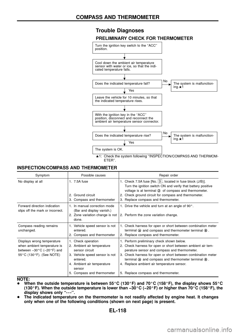
PRELIMINARY CHECK FOR THERMOMETER
Turn the ignition key switch to the ``ACC''
position.
Cool down the ambient air temperature
sensor with water or ice, so that the indi-
cated temperature falls.
Does the indicated temperature fall?
Ye s
cNo
The system is malfunction-
ing..1
Leave the vehicle for 10 minutes, so that
the indicated temperature rises.
With the ignition key in the ``ACC''
position, disconnect and reconnect the
ambient air temperature sensor connector.
Does the indicated temperature rise?
Ye s
cNo
The system is malfunction-
ing..1
The system is OK.
.1: Check the system following ``INSPECTION/COMPASS AND THERMOM-
ETER''.
INSPECTION/COMPASS AND THERMOMETER
Symptom Possible causes Repair order
No display at all 1. 7.5A fuse
2. Ground circuit
3. Compass and thermometer1. Check 7.5A fuse [No.
9, located in fuse block (J/B)].
Turn the ignition switch ON and verify that battery positive
voltage is at terminalj
2of compass and thermometer.
2. Check ground circuit for compass and thermometer.
3. Replace compass and thermometer.
Forward direction indication
slips off the mark or incorrect.1. In manual correction mode
(Bar and display vanish.)
2. Zone variation change is not
done.1. Drive the vehicle and turn at an angle of 90É.
2. Perform the zone variation change.
Compass reading remains
unchanged.1. Vehicle speed sensor is not
entered.
2. Compass and thermometer1. Check harness for open or short between combination meter
terminalj
26and compass and thermometer terminalj8.
2. Replace compass and thermometer.
Displays wrong temperature
when ambient temperature is
between þ30ÉC (þ20ÉF) and
55ÉC (130ÉF). (See NOTE)1. Check operation
2. Ambient air temperature
sensor circuit
3. Vehicle speed sensor is not
entered.
4. Ambient air temperature
sensor
5. Compass and thermometer1. Perform preliminary check shown below.
2. Check harness for open or short between ambient air tem-
perature sensor and compass and thermometer.
3. Check harness for open or short between combination meter
terminalj
26and compass and thermometer terminalj8.
4. Replace ambient air temperature sensor.
5. Replace compass and thermometer.
NOTE:
+When the outside temperature is between 55ÉC (130ÉF) and 70ÉC (158ÉF), the display shows 55ÉC
(130ÉF). When the outside temperature is lower than þ30ÉC (þ20ÉF) or higher than 70ÉC (158ÉF), the
display shows only ``- - -''.
+The indicated temperature on the thermometer is not readily affected by engine heat. It changes
only when one of the following conditions (shown on next page) is present.
.
.
.
.
.
.
COMPASS AND THERMOMETER
EL-118
Page 143 of 326
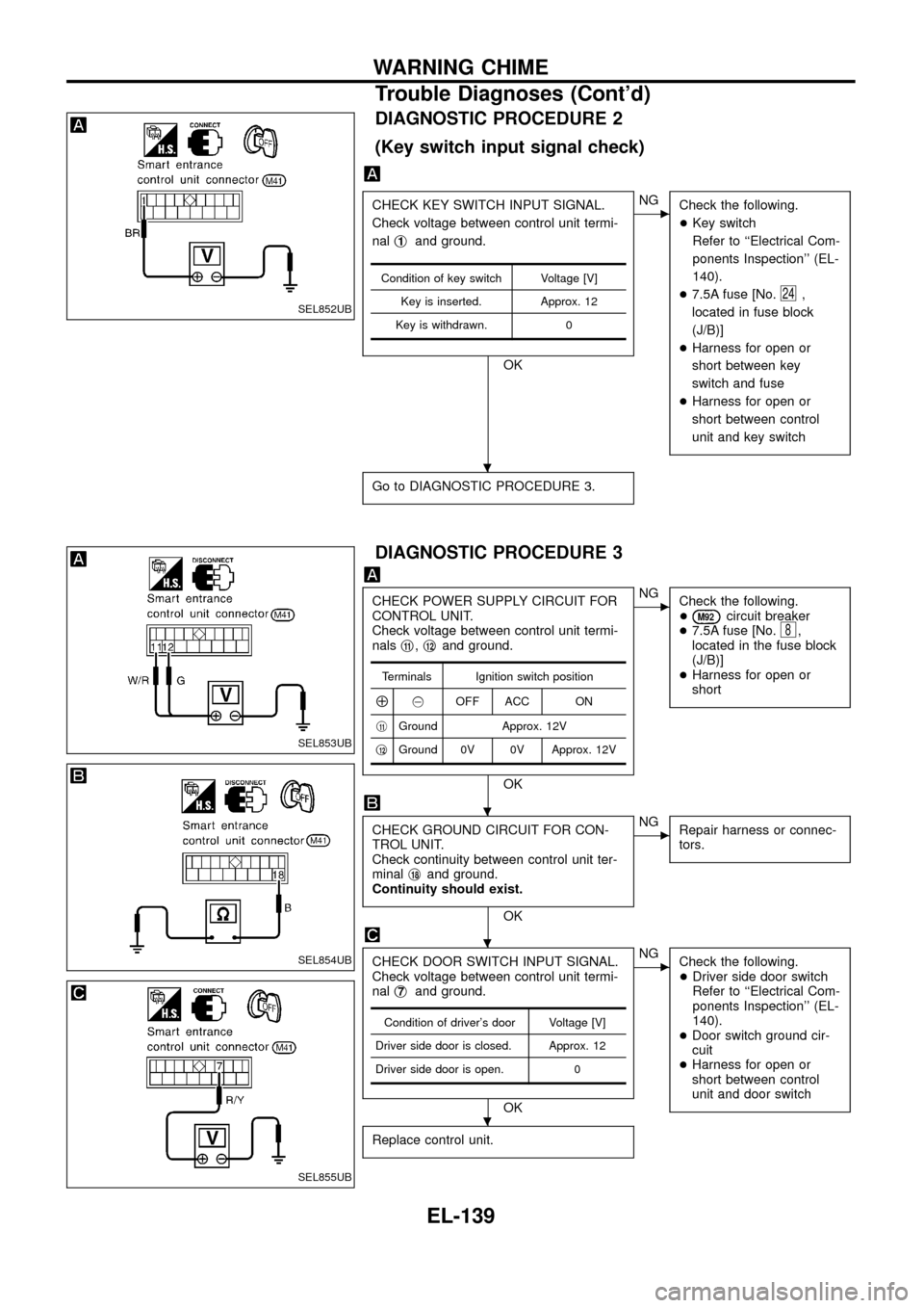
DIAGNOSTIC PROCEDURE 2
(Key switch input signal check)
CHECK KEY SWITCH INPUT SIGNAL.
Check voltage between control unit termi-
nalj
1and ground.
OK
cNG
Check the following.
+Key switch
Refer to ``Electrical Com-
ponents Inspection'' (EL-
140).
+7.5A fuse [No.
24,
located in fuse block
(J/B)]
+Harness for open or
short between key
switch and fuse
+Harness for open or
short between control
unit and key switch
Go to DIAGNOSTIC PROCEDURE 3.
Condition of key switch Voltage [V]
Key is inserted. Approx. 12
Key is withdrawn. 0
DIAGNOSTIC PROCEDURE 3
CHECK POWER SUPPLY CIRCUIT FOR
CONTROL UNIT.
Check voltage between control unit termi-
nalsj
11,j12and ground.
OK
cNG
Check the following.
+
M92circuit breaker
+7.5A fuse [No.8,
located in the fuse block
(J/B)]
+Harness for open or
short
CHECK GROUND CIRCUIT FOR CON-
TROL UNIT.
Check continuity between control unit ter-
minalj
18and ground.
Continuity should exist.
OK
cNG
Repair harness or connec-
tors.
CHECK DOOR SWITCH INPUT SIGNAL.
Check voltage between control unit termi-
nalj
7and ground.
OK
cNG
Check the following.
+Driver side door switch
Refer to ``Electrical Com-
ponents Inspection'' (EL-
140).
+Door switch ground cir-
cuit
+Harness for open or
short between control
unit and door switch
Replace control unit.
Terminals Ignition switch position
Å@OFF ACC ON
j
11Ground Approx. 12V
j
12Ground 0V 0V Approx. 12V
Condition of driver's door Voltage [V]
Driver side door is closed. Approx. 12
Driver side door is open. 0
SEL852UB
SEL853UB
SEL854UB
SEL855UB
.
.
.
.
WARNING CHIME
Trouble Diagnoses (Cont'd)
EL-139
Page 167 of 326
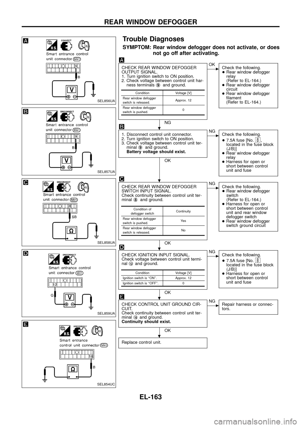
Trouble Diagnoses
SYMPTOM: Rear window defogger does not activate, or does
not go off after activating.
CHECK REAR WINDOW DEFOGGER
OUTPUT SIGNAL.
1. Turn ignition switch to ON position.
2. Check voltage between control unit har-
ness terminalsj
9and ground.
NG
cOK
Check the following.
+Rear window defogger
relay
(Refer to EL-164.)
+Rear window defogger
circuit
+Rear window defogger
®lament
(Refer to EL-164.)
1. Disconnect control unit connector.
2. Turn ignition switch to ON position.
3. Check voltage between control unit ter-
minalj
9and ground.
Battery voltage should exist.
OK
cNG
Check the following.
+7.5A fuse [No.
8,
located in the fuse block
(J/B)]
+Rear window defogger
relay
+Harness for open or
short between control
unit and fuse
CHECK REAR WINDOW DEFOGGER
SWITCH INPUT SIGNAL.
Check continuity between control unit ter-
minalj
8and ground.
OK
cNG
Check the following.
+Rear window defogger
switch
(Refer to EL-164.)
+Harness for open or
short between control
unit and rear window
defogger switch
+Rear window defogger
switch ground circuit
CHECK IGNITION INPUT SIGNAL.
Check voltage between control unit termi-
nalj
12and ground.
OK
cNG
Check the following.
+7.5A fuse [No.
8located in the fuse block
(J/B)]
+Harness for open or
short between control
unit and fuse
CHECK CONTROL UNIT GROUND CIR-
CUIT.
Check continuity between control unit ter-
minalj
18and ground.
Continuity should exist.
OK
cNG
Repair harness or connec-
tors.
Replace control unit.
Condition Voltage [V]
Rear window defogger
switch is released.Approx. 12
Rear window defogger
switch is pushed.0
Condition of
defogger switchContinuity
Rear window defogger
switch is pushed.Ye s
Rear window defogger
switch is released.No
Condition Voltage [V]
Ignition switch is ``ON''. Approx. 12
Ignition switch is ``OFF''. 0
SEL856UA
SEL857UA
SEL858UA
SEL859UA
SEL854UC
.
.
.
.
.
REAR WINDOW DEFOGGER
EL-163
Page 184 of 326
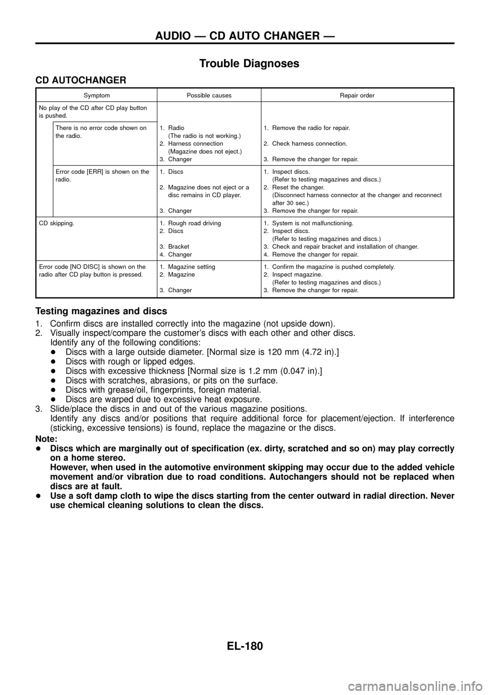
Trouble Diagnoses
CD AUTOCHANGER
Symptom Possible causes Repair order
No play of the CD after CD play button
is pushed.
There is no error code shown on
the radio.1. Radio
(The radio is not working.)
2. Harness connection
(Magazine does not eject.)
3. Changer1. Remove the radio for repair.
2. Check harness connection.
3. Remove the changer for repair.
Error code [ERR] is shown on the
radio.1. Discs
2. Magazine does not eject or a
disc remains in CD player.
3. Changer1. Inspect discs.
(Refer to testing magazines and discs.)
2. Reset the changer.
(Disconnect harness connector at the changer and reconnect
after 30 sec.)
3. Remove the changer for repair.
CD skipping. 1. Rough road driving
2. Discs
3. Bracket
4. Changer1. System is not malfunctioning.
2. Inspect discs.
(Refer to testing magazines and discs.)
3. Check and repair bracket and installation of changer.
4. Remove the changer for repair.
Error code [NO DISC] is shown on the
radio after CD play button is pressed.1. Magazine setting
2. Magazine
3. Changer1. Con®rm the magazine is pushed completely.
2. Inspect magazine.
(Refer to testing magazines and discs.)
3. Remove the changer for repair.
Testing magazines and discs
1. Con®rm discs are installed correctly into the magazine (not upside down).
2. Visually inspect/compare the customer's discs with each other and other discs.
Identify any of the following conditions:
+Discs with a large outside diameter. [Normal size is 120 mm (4.72 in).]
+Discs with rough or lipped edges.
+Discs with excessive thickness [Normal size is 1.2 mm (0.047 in).]
+Discs with scratches, abrasions, or pits on the surface.
+Discs with grease/oil, ®ngerprints, foreign material.
+Discs are warped due to excessive heat exposure.
3. Slide/place the discs in and out of the various magazine positions.
Identify any discs and/or positions that require additional force for placement/ejection. If interference
(sticking, excessive tensions) is found, replace the magazine or the discs.
Note:
+Discs which are marginally out of speci®cation (ex. dirty, scratched and so on) may play correctly
on a home stereo.
However, when used in the automotive environment skipping may occur due to the added vehicle
movement and/or vibration due to road conditions. Autochangers should not be replaced when
discs are at fault.
+Use a soft damp cloth to wipe the discs starting from the center outward in radial direction. Never
use chemical cleaning solutions to clean the discs.
AUDIO Ð CD AUTO CHANGER Ð
EL-180
Page 213 of 326
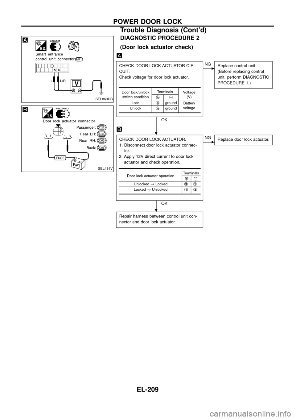
DIAGNOSTIC PROCEDURE 2
(Door lock actuator check)
CHECK DOOR LOCK ACTUATOR CIR-
CUIT.
Check voltage for door lock actuator.
OK
cNG
Replace control unit.
(Before replacing control
unit, perform DIAGNOSTIC
PROCEDURE 1.)
CHECK DOOR LOCK ACTUATOR.
1. Disconnect door lock actuator connec-
tor.
2. Apply 12V direct current to door lock
actuator and check operation.
OK
cNG
Replace door lock actuator.
Repair harness between control unit con-
nector and door lock actuator.
Door lock/unlock
switch conditionTerminals
Voltage
(V)
Å@
Lockj
15ground
Battery
voltage
Unlockj
16ground
Door lock actuator operationTerminalsÅ@
Unlocked®Lockedj
3j1
Locked®Unlockedj1j3
SEL863UB
SEL434V
.
.
POWER DOOR LOCK
Trouble Diagnosis (Cont'd)
EL-209