1998 NISSAN PATROL stop start
[x] Cancel search: stop startPage 46 of 326
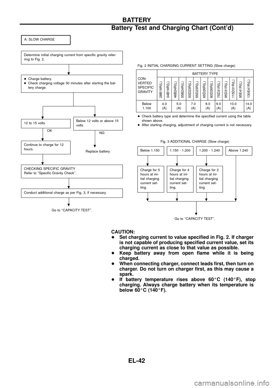
A: SLOW CHARGE
Determine initial charging current from speci®c gravity refer-
ring to Fig. 2.
+Charge battery.
+Check charging voltage 30 minutes after starting the bat-
tery charge.
12 to 15 volts
OKBelow 12 volts or above 15
voltsNG
Continue to charge for 12
hours.
Replace battery.
CHECKING SPECIFIC GRAVITY
Refer to ``Speci®c Gravity Check''.
Conduct additional charge as per Fig. 3, if necessary.
Go to ``CAPACITY TEST''.Fig. 2 INITIAL CHARGING CURRENT SETTING (Slow charge)
CON-
VERTED
SPECIFIC
GRAVITYBATTERY TYPE
28B19R(L)
34B19R(L)
46B24R(L)
55B24R(L)
50D23R(L)
55D23R(L)
65D26R(L)
80D26R(L)
75D31R(L)
95D31R(L)
115D31R(L)
95E41R(L)
130E41R(L)
Below
1.1004.0
(A)5.0
(A)7.0
(A)8.0
(A)9.0
(A)10.0
(A)14.0
(A)
+Check battery type and determine the speci®ed current using the table
shown above.
+After starting charging, adjustment of charging current is not necessary.
Fig. 3 ADDITIONAL CHARGE (Slow charge)
Below 1.150
1.150 - 1.2001.200 - 1.240Above 1.240
Charge for 5
hours at ini-
tial charging
current set-
ting.Charge for 4
hours at ini-
tial charging
current set-
ting.Charge for 2
hours at ini-
tial charging
current set-
ting.
Go to ``CAPACITY TEST''.
.
CAUTION:
+Set charging current to value speci®ed in Fig. 2. If charger
is not capable of producing speci®ed current value, set its
charging current as close to that value as possible.
+Keep battery away from open ¯ame while it is being
charged.
+When connecting charger, connect leads ®rst, then turn on
charger. Do not turn on charger ®rst, as this may cause a
spark.
+If battery temperature rises above 60ÉC (140ÉF), stop
charging. Always charge battery when its temperature is
below 60ÉC (140ÉF).
.
..
.
.
.
.
.
...
....
BATTERY
Battery Test and Charging Chart (Cont'd)
EL-42
Page 47 of 326
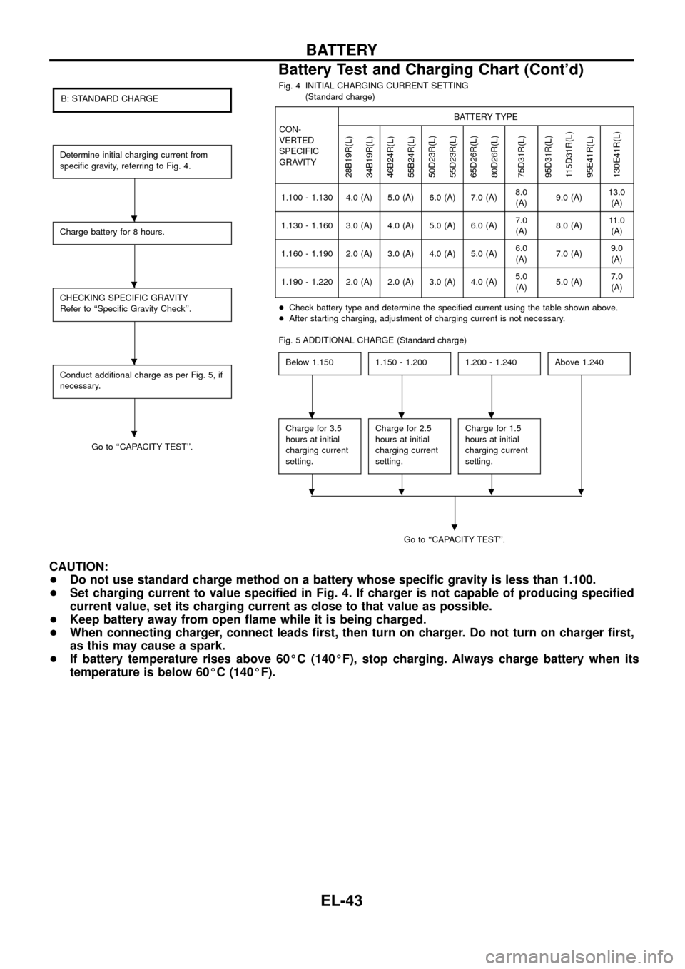
B: STANDARD CHARGE
Determine initial charging current from
speci®c gravity, referring to Fig. 4.
Charge battery for 8 hours.
CHECKING SPECIFIC GRAVITY
Refer to ``Speci®c Gravity Check''.
Conduct additional charge as per Fig. 5, if
necessary.
Go to ``CAPACITY TEST''.Fig. 4 INITIAL CHARGING CURRENT SETTING
(Standard charge)
CON-
VERTED
SPECIFIC
GRAVITYBATTERY TYPE
28B19R(L)
34B19R(L)
46B24R(L)
55B24R(L)
50D23R(L)
55D23R(L)
65D26R(L)
80D26R(L)
75D31R(L)
95D31R(L)
115D31R(L)
95E41R(L)
130E41R(L)
1.100 - 1.130 4.0 (A) 5.0 (A) 6.0 (A) 7.0 (A)8.0
(A)9.0 (A)13.0
(A)
1.130 - 1.160 3.0 (A) 4.0 (A) 5.0 (A) 6.0 (A)7.0
(A)8.0 (A)11.0
(A)
1.160 - 1.190 2.0 (A) 3.0 (A) 4.0 (A) 5.0 (A)6.0
(A)7.0 (A)9.0
(A)
1.190 - 1.220 2.0 (A) 2.0 (A) 3.0 (A) 4.0 (A)5.0
(A)5.0 (A)7.0
(A)
+Check battery type and determine the speci®ed current using the table shown above.
+After starting charging, adjustment of charging current is not necessary.
Fig. 5 ADDITIONAL CHARGE (Standard charge)
Below 1.150
1.150 - 1.2001.200 - 1.240Above 1.240
Charge for 3.5
hours at initial
charging current
setting.Charge for 2.5
hours at initial
charging current
setting.Charge for 1.5
hours at initial
charging current
setting.
Go to ``CAPACITY TEST''.
.
CAUTION:
+Do not use standard charge method on a battery whose speci®c gravity is less than 1.100.
+Set charging current to value speci®ed in Fig. 4. If charger is not capable of producing speci®ed
current value, set its charging current as close to that value as possible.
+Keep battery away from open ¯ame while it is being charged.
+When connecting charger, connect leads ®rst, then turn on charger. Do not turn on charger ®rst,
as this may cause a spark.
+If battery temperature rises above 60ÉC (140ÉF), stop charging. Always charge battery when its
temperature is below 60ÉC (140ÉF).
.
.
.
.
...
....
BATTERY
Battery Test and Charging Chart (Cont'd)
EL-43
Page 48 of 326
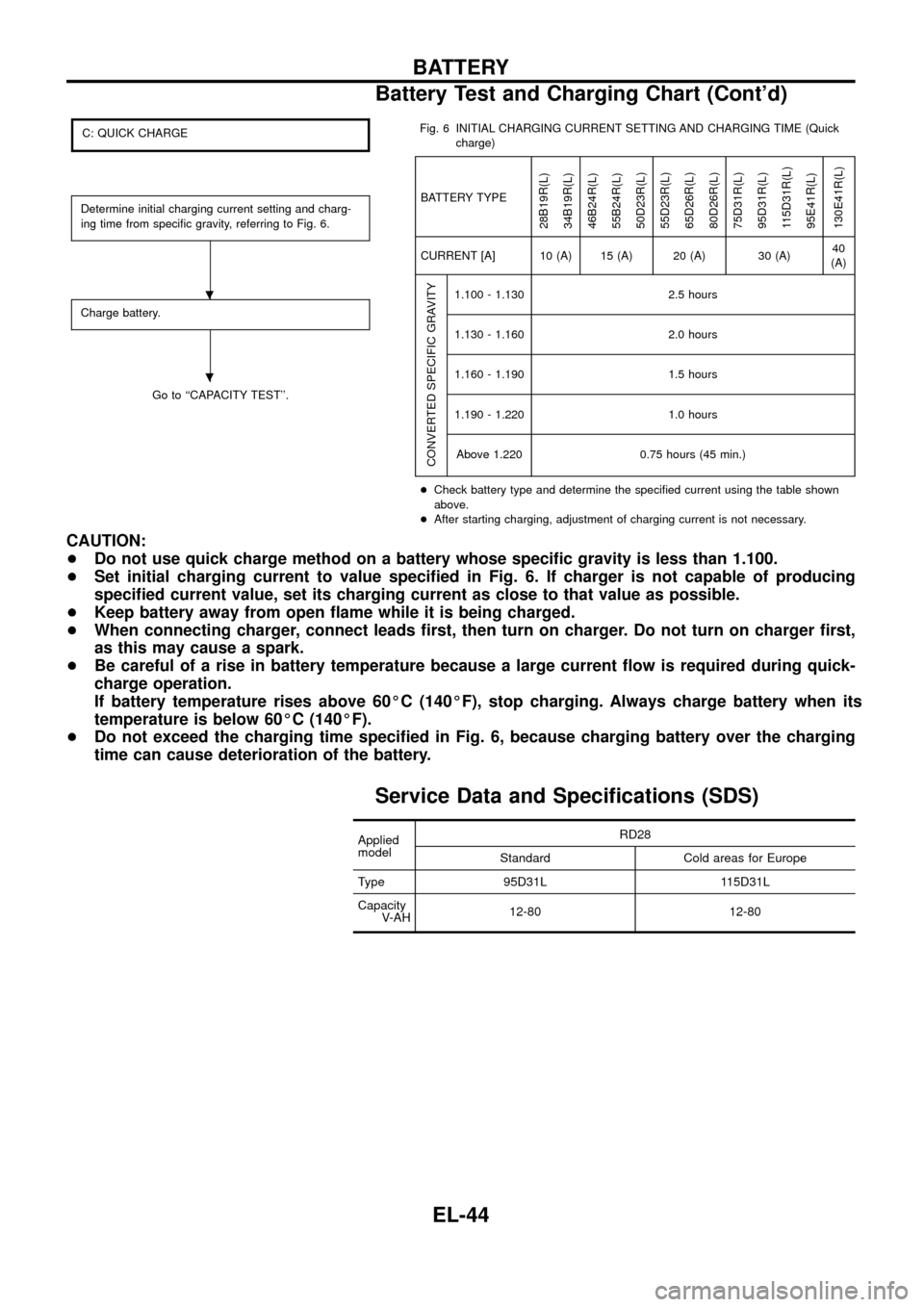
C: QUICK CHARGE
Determine initial charging current setting and charg-
ing time from speci®c gravity, referring to Fig. 6.
Charge battery.
Go to ``CAPACITY TEST''.Fig. 6 INITIAL CHARGING CURRENT SETTING AND CHARGING TIME (Quick
charge)
BATTERY TYPE
28B19R(L)
34B19R(L)
46B24R(L)
55B24R(L)
50D23R(L)
55D23R(L)
65D26R(L)
80D26R(L)
75D31R(L)
95D31R(L)
115D31R(L)
95E41R(L)
130E41R(L)
CURRENT [A] 10 (A) 15 (A) 20 (A) 30 (A)40
(A)
CONVERTED SPECIFIC GRAVITY
1.100 - 1.130 2.5 hours
1.130 - 1.160 2.0 hours
1.160 - 1.190 1.5 hours
1.190 - 1.220 1.0 hours
Above 1.220 0.75 hours (45 min.)
+Check battery type and determine the speci®ed current using the table shown
above.
+After starting charging, adjustment of charging current is not necessary.
CAUTION:
+Do not use quick charge method on a battery whose speci®c gravity is less than 1.100.
+Set initial charging current to value speci®ed in Fig. 6. If charger is not capable of producing
speci®ed current value, set its charging current as close to that value as possible.
+Keep battery away from open ¯ame while it is being charged.
+When connecting charger, connect leads ®rst, then turn on charger. Do not turn on charger ®rst,
as this may cause a spark.
+Be careful of a rise in battery temperature because a large current ¯ow is required during quick-
charge operation.
If battery temperature rises above 60ÉC (140ÉF), stop charging. Always charge battery when its
temperature is below 60ÉC (140ÉF).
+Do not exceed the charging time speci®ed in Fig. 6, because charging battery over the charging
time can cause deterioration of the battery.
Service Data and Speci®cations (SDS)
Applied
modelRD28
Standard Cold areas for Europe
Type 95D31L 115D31L
Capacity
V-AH12-80 12-80
.
.
BATTERY
Battery Test and Charging Chart (Cont'd)
EL-44
Page 50 of 326
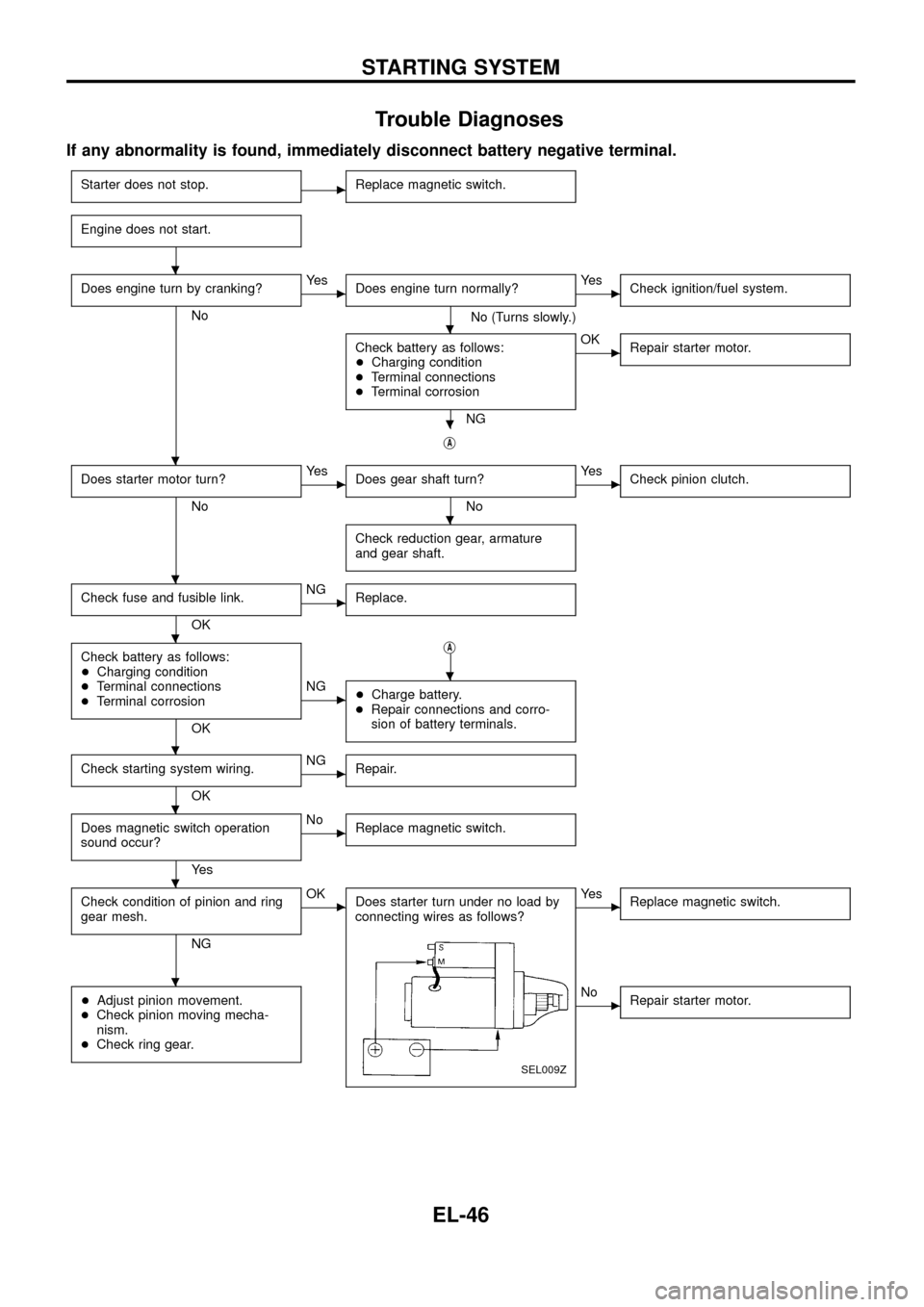
Trouble Diagnoses
If any abnormality is found, immediately disconnect battery negative terminal.
Starter does not stop.cReplace magnetic switch.
Engine does not start.
Does engine turn by cranking?
No
cYe s
Does engine turn normally?
No (Turns slowly.)
cYe s
Check ignition/fuel system.
Check battery as follows:
+Charging condition
+Terminal connections
+Terminal corrosion
NG
cOK
Repair starter motor.
jA
Does starter motor turn?
No
cYe s
Does gear shaft turn?
No
cYe s
Check pinion clutch.
Check reduction gear, armature
and gear shaft.
Check fuse and fusible link.
OK
cNG
Replace.
Check battery as follows:
+Charging condition
+Terminal connections
+Terminal corrosion
OKj
A
cNG
+Charge battery.
+Repair connections and corro-
sion of battery terminals.
Check starting system wiring.
OK
cNG
Repair.
Does magnetic switch operation
sound occur?
Ye s
cNo
Replace magnetic switch.
Check condition of pinion and ring
gear mesh.
NG
cOK
Does starter turn under no load by
connecting wires as follows?
SEL009Z
cYe s
Replace magnetic switch.
+Adjust pinion movement.
+Check pinion moving mecha-
nism.
+Check ring gear.cNo
Repair starter motor.
.
.
.
.
.
.
.
.
.
.
.
.
STARTING SYSTEM
EL-46
Page 54 of 326
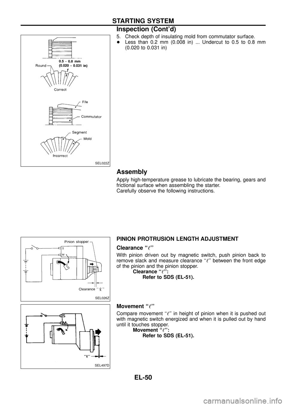
5. Check depth of insulating mold from commutator surface.
+Less than 0.2 mm (0.008 in) ... Undercut to 0.5 to 0.8 mm
(0.020 to 0.031 in)
Assembly
Apply high-temperature grease to lubricate the bearing, gears and
frictional surface when assembling the starter.
Carefully observe the following instructions.
PINION PROTRUSION LENGTH ADJUSTMENT
Clearance ``!''
With pinion driven out by magnetic switch, push pinion back to
remove slack and measure clearance ``!'' between the front edge
of the pinion and the pinion stopper.
Clearance ``!'':
Refer to SDS (EL-51).
Movement ``!''
Compare movement ``!'' in height of pinion when it is pushed out
with magnetic switch energized and when it is pulled out by hand
until it touches stopper.
Movement ``!'':
Refer to SDS (EL-51).
SEL022Z
SEL026Z
SEL497D
STARTING SYSTEM
Inspection (Cont'd)
EL-50
Page 55 of 326
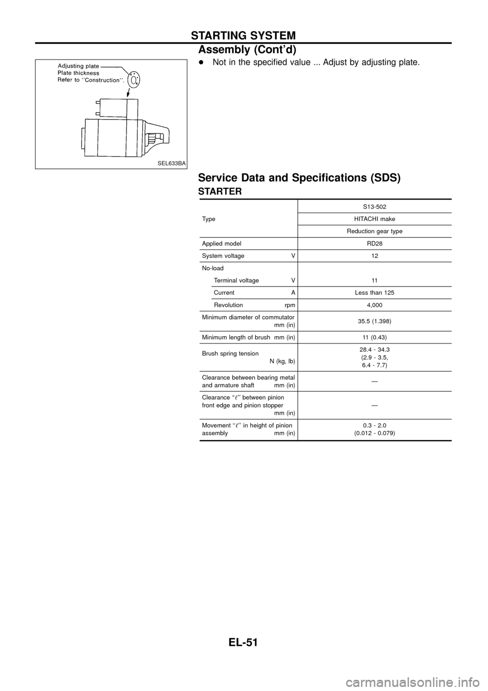
+Not in the speci®ed value ... Adjust by adjusting plate.
Service Data and Speci®cations (SDS)
STARTER
TypeS13-502
HITACHI make
Reduction gear type
Applied model RD28
System voltage V 12
No-load
Terminal voltage V 11
Current A Less than 125
Revolution rpm 4,000
Minimum diameter of commutator
mm (in)35.5 (1.398)
Minimum length of brush mm (in) 11 (0.43)
Brush spring tension
N (kg, lb)28.4 - 34.3
(2.9 - 3.5,
6.4 - 7.7)
Clearance between bearing metal
and armature shaft mm (in)Ð
Clearance ``!'' between pinion
front edge and pinion stopper
mm (in)Ð
Movement ``!'' in height of pinion
assembly mm (in)0.3 - 2.0
(0.012 - 0.079)
SEL633BA
STARTING SYSTEM
Assembly (Cont'd)
EL-51
Page 73 of 326
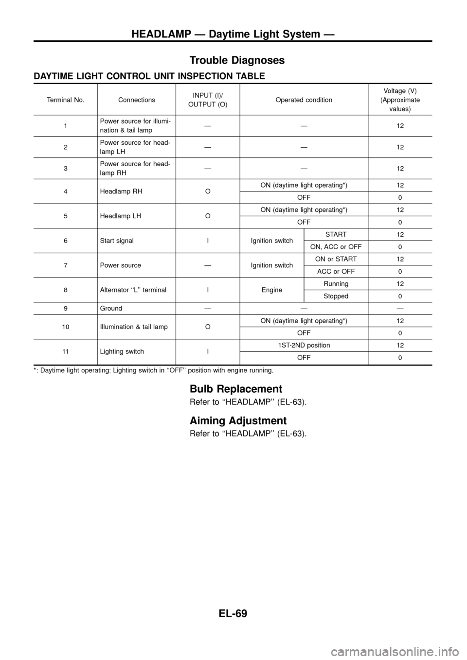
Trouble Diagnoses
DAYTIME LIGHT CONTROL UNIT INSPECTION TABLE
Terminal No. ConnectionsINPUT (I)/
OUTPUT (O)Operated conditionVoltage (V)
(Approximate
values)
1Power source for illumi-
nation & tail lampÐÐ12
2Power source for head-
lamp LHÐÐ12
3Power source for head-
lamp RHÐÐ12
4 Headlamp RH OON (daytime light operating*) 12
OFF 0
5 Headlamp LH OON (daytime light operating*) 12
OFF 0
6 Start signal I Ignition switchSTART 12
ON, ACC or OFF 0
7 Power source Ð Ignition switchON or START 12
ACC or OFF 0
8 Alternator ``L'' terminal I EngineRunning 12
Stopped 0
9 Ground Ð Ð Ð
10 Illumination & tail lamp OON (daytime light operating*) 12
OFF 0
11 Lighting switch I1STz2ND position 12
OFF 0
*: Daytime light operating: Lighting switch in ``OFF'' position with engine running.
Bulb Replacement
Refer to ``HEADLAMP'' (EL-63).
Aiming Adjustment
Refer to ``HEADLAMP'' (EL-63).
HEADLAMP Ð Daytime Light System Ð
EL-69
Page 74 of 326
![NISSAN PATROL 1998 Y61 / 5.G Electrical System Workshop Manual System Description
CIRCUIT OPERATION
[Example]
Aiming switch ``0
+When the aiming switch is set to ``0, the motor will not start.
This is because the power terminals are positioned at the non-
con NISSAN PATROL 1998 Y61 / 5.G Electrical System Workshop Manual System Description
CIRCUIT OPERATION
[Example]
Aiming switch ``0
+When the aiming switch is set to ``0, the motor will not start.
This is because the power terminals are positioned at the non-
con](/manual-img/5/616/w960_616-73.png)
System Description
CIRCUIT OPERATION
[Example]
Aiming switch ``0''
+When the aiming switch is set to ``0'', the motor will not start.
This is because the power terminals are positioned at the non-
conductive section of the sensor's rotary unit.
Aiming switch ``0''®``1''
+When the aiming switch is moved from ``0'' to ``1'', the sensor's
conductive section activates the relay. Power is supplied
through the relay to the motor. The headlamps will then move
in the ``DOWN'' direction.
+The motor continues to rotate while the rotary unit of the sen-
sor moves from point A to point B.
+The power terminals will then be positioned at the nonconduc-
tive section, disconnecting the power to the motor. The motor
will then stop.
Aiming switch ``1''®``0''
+When the aiming switch is moved from ``1'' to ``0'', the sensor's
conductive section activates the relay. Power is supplied
through the relay to the motor. The motor will rotate to move the
headlamps in the ``UP'' direction.
+When the rotary unit of the sensor moves from point B to point
A, the motor will stop.
SEL465M
SEL364P
SEL365P
HEADLAMP Ð Headlamp Aiming Control Ð
EL-70