Page 21 of 396
ENGINE – Crankshaft Oil Seal11-15
CRANKSHAFT OIL SEAL
REMOVAL AND INSTALLATION
4
3 2
1
5127 – 137
{13.0 – 14.0}
3
Unit: Nm {kgf�m} Engine oil
5
Crankshaft front oil seal removal
steps
�Timing belt and timing belt B
(Refer to P.11-21.)
�Crank angle sensor
(Refer to GROUP 16.)
1. Crankshaft sprocket B
2. Key
�C�3. Crankshaft front oil sealCrankshaft rear oil seal removal
steps
�Transmission assembly
�Clutch cover and disc
�A��B�4. Flywheel
�A�5. Crankshaft rear oil seal
Page 22 of 396

ENGINE – Crankshaft Oil Seal11-16
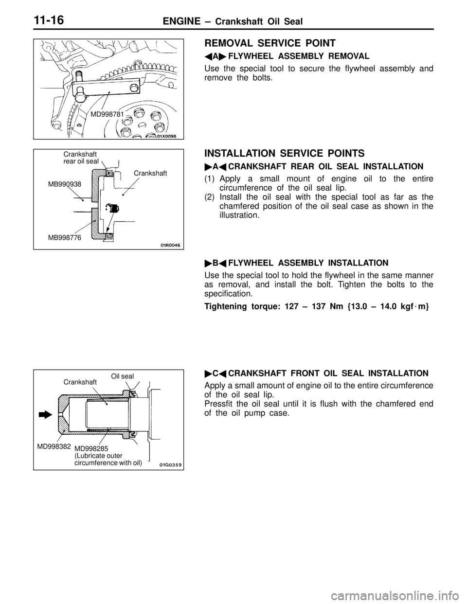
REMOVAL SERVICE POINT
�A�FLYWHEEL ASSEMBLY REMOVAL
Use the special tool to secure the flywheel assembly and
remove the bolts.
INSTALLATION SERVICE POINTS
�A�CRANKSHAFT REAR OIL SEAL INSTALLATION
(1) Apply a small mount of engine oil to the entire
circumference of the oil seal lip.
(2) Install the oil seal with the special tool as far as the
chamfered position of the oil seal case as shown in the
illustration.
�B�FLYWHEEL ASSEMBLY INSTALLATION
Use the special tool to hold the flywheel in the same manner
as removal, and install the bolt. Tighten the bolts to the
specification.
Tightening torque: 127 – 137 Nm {13.0 – 14.0 kgf�m}
�C�CRANKSHAFT FRONT OIL SEAL INSTALLATION
Apply a small amount of engine oil to the entire circumference
of the oil seal lip.
Pressfit the oil seal until it is flush with the chamfered end
of the oil pump case.
MD998781
Crankshaft
rear oil seal
MB990938
MB998776Crankshaft
Crankshaft
MD998382
Oil seal
MD998285
(Lubricate outer
circumference with oil)
Page 23 of 396

ENGINE – Cylinder Head Gasket11-17
CYLINDER HEAD GASKET
REMOVAL AND INSTALLATION
Pre-removal Operation
(1) Fuel Discharge Prevention
(2) Engine Oil Removal
(3) Strut Tower Bar Removal
(4) Timing Belt Removal (Refer to P.11-21.)
(5) Thermostat Case Assembly Removal
(Refer to GROUP 14 – Water Hose Pipe.)
(6) Front Exhaust Pipe Removal (Refer to GROUP 15.)Post-installation Operation
(1) Front Exhaust Pipe Installation
(Refer to GROUP 15.)
(2) Thermostat Case Assembly Installation
(Refer to GROUP 14 – Water Hose Pipe.)
(3) Engine Oil Filling
(4) Timing Belt Installation (Refer to P.11-21.)
(5) Strut Tower Bar Installation
(6) Accelerator Cable Adjustment
O-ringDelivery pipe
Engine oil
12 – 15 {1.2 – 1.5}
5
9 {0.9}5 {0.5} 3 {0.3} 10 {1.0}
19
14
153
16
18
10
17
8
9
8
11
8
7
201
2
Unit: Nm {kgf�m}
18
6
3
13
12 4
Removal steps
1. Center cover
2. Accelerator cable connection
3. Ignition coil connector
4. Ignition coil
5. Crank angle sensor connector
6. Crank angle sensor bracket con-
nection
7. Brake booster vacuum hose con-
nection
8. Vacuum hose connection
9. TPS connector
10. ISC motor connector11. Water hose connection
12. Oxygen sensor connector
13. Injector connector
14. Cam position sensor connector
15. Coolant temperature sensor con-
nector
16. Water temperature gauge unit con-
nector
17. Control harness
�D�18. Fuel pipe pressure hose connection
19. Fuel return hose connection
20. Oil level gauge guide assembly
Page 24 of 396
ENGINE – Cylinder Head Gasket11-18
10 mm
10 mm
10 mm
Semi-drying sealant:
THREEBOND 1207D
29
9 {0.9}
Unit: Nm {kgf�m}
3.4 {0.35}
30 {3.1} 22 {2.2}
9 {0.9}
30 {3.1}
32
33
28
2725
26
2430 23
2122
31
78 → 0 → 20 → +90� → +90�
{8.0 → 0 → 2.0 → +90� → +90�}
22
22
23
10 mm 10 mm
Removal steps
21. PCV hose connection
22. Rocker cover
23. Semi-circular packing
24. Starter
25. Oil return pipe
�C�26. Oil return pipe gasket
27. Vacuum tank/solenoid valve/vacuum
hose assembly28. Intake manifold stay
29. Heater hose connection
30. Alternator brace stay mounting bolt
�A��B�31. Cylinder head bolt
32. Cylinder head assembly
�A�33. Cylinder head gasket
Page 25 of 396
ENGINE – Cylinder Head Gasket11-19
REMOVAL SERVICE POINT
�A�CYLINDER HEAD BOLT REMOVAL
Loosen the bolts in 2 or 3 steps in order of the numbers
shown in the illustration, and remove the cylinder head
assembly.
INSTALLATION SERVICE POINTS
�A�CYLINDER HEAD GASKET INSTALLATION
(1) Wipe off all oil and grease from the gasket mounting
surface.
(2) Install so that the shapes of the cylinder head holes match
the shapes of the respective cylinder head gasket holes.
�B�CYLINDER HEAD BOLT INSTALLATION
(1) When installing the cylinder head bolts, the length below
the head of the bolts should be within the limit.
If it is outside the limit, replace the bolts.
Limit (A): 99.4 mm
(2) Apply a small amount of engine oil to the thread section
and the washer of the cylinder head bolt.
Intake sideMB991654
Exhaust sideFront of engine
Cylinder head bolt
Washer
(Engine
oil)
Cylinder
head A
Page 26 of 396

ENGINE – Cylinder Head Gasket11-20
(3) Tighten the bolts by the following procedure.
StepOperation
1Tighten to 78 Nm {8.0 kgf�m} in the order shown in the
illustration.
2Fully loosen in the reverse order of that shown in the
illustration.
3Tighten to 20 Nm {2.0 kgf�m} in the order shown in the
illustration.
4Mark the head of the cylinder head bolt and cylinder head
by paint, then tighten 90� of a turn in the order shown in
the illustration.
5Tighten 90� of a turn in the order shown in the illustration.
Check that the painted mark of the head bolt is lined up
with that of the cylinder head.
Caution
(1) Always make a tightening angle just 90�. If it is less
than 90�, the head bolt will be loosened.
(2) If it is more than 90�, remove the head bolt and repeat
the procedure from step 1.
�C�OIL RETURN PIPE GASKET INSTALLATION
Install the gasket with the printed portion toward the oil pan.
�D�HIGH-PRESSURE FUEL HOSE INSTALLATION
(1) Apply a small amount of new engine oil to the O-ring,
then fit the O-ring in the delivery pipe.
Caution
Do not let any engine oil get into the delivery pipe.
(2) Check that the high pressure hose turns smoothly.
If the hose does not turn smoothly, the O-ring is probably
being clamped. Disconnect the high-pressure fuel hose
and check the O-ring for damage. After this, re-install
the hose to the delivery pipe and check that the hose
turns smoothly.
(3) Tighten the mounting bolts to the specification.
Intake sideMB991654
Exhaust sideFront of engine
Step 4
90�
Painted markStep 5
90�
Painted mark
GasketPrinted portion
Page 27 of 396

ENGINE – Timing Belt11-21
TIMING BELT
REMOVAL AND INSTALLATION
1
2
3
4 56
7
8
910
11 1213
14 15
16 171821
22
23
242526
27
28
20
19
11 {1.1}
11 {1.1} 11 {1.1}
88 {9.0}
49 {5.0}
9 {0.9}
48 {4.9}54 {5.5}49 {5.0} 118 {12.0}
9 {0.9}3.5 {0.35}
49 {5.0}
45 {4.6}
19 {1.9}30 {3.1} 24 {2.4}24 {2.4}
Unit: Nm {kgf�m}
Removal steps
1. Front upper cover
2. Front center cover
3. Front lower cover
4. Bracket
�A��L�5. Timing belt
�K�6. Tensioner pulley
7. Tensioner arm
�J�8. Auto tensioner
9. Idle pulley
10. Crankshaft position sensor
�B��I�11. Oil pump sprocket
�C��H�12. Crankshaft bolt
�D�13. Crankshaft sprocket
14. Sensing blade15. Tensioner B
�E��G�16. Timing belt B
�F��F�17. Counterbalance shaft sprocket
�E�18. Spacer
�G�19. Crankshaft sprocket B
20. Crankshaft key
�D�21. Rocker cover
�C�22. Semi-circular packing
�B�23. Engine support bracket
�H��A�24. Camshaft sprocket bolt
25. Camshaft sprocket
26. Timing belt rear right cover
27. Timing belt rear left upper cover
28. Timing belt rear left lower cover
Page 28 of 396

ENGINE – Timing Belt11-22
REMOVAL SERVICE POINTS
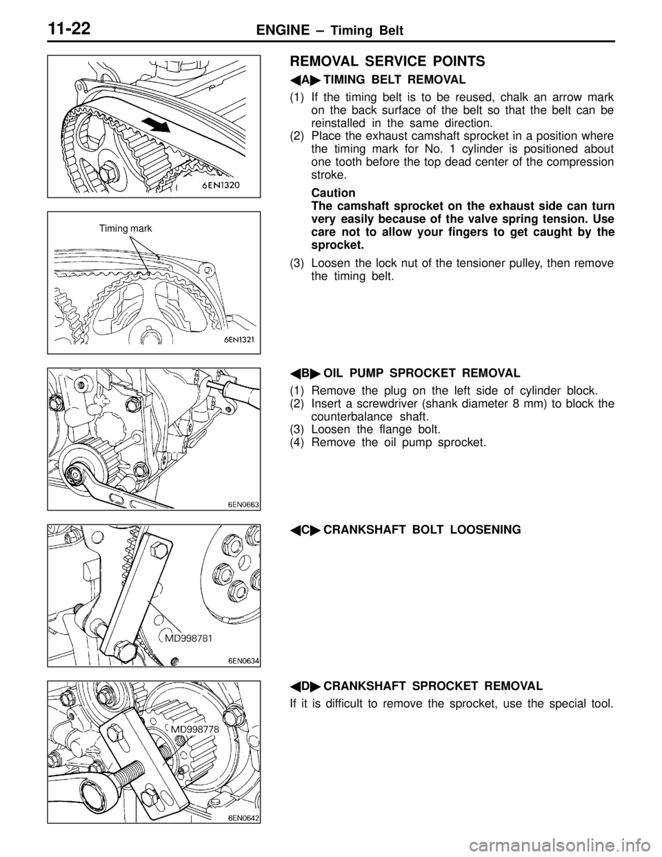
�A�TIMING BELT REMOVAL
(1) If the timing belt is to be reused, chalk an arrow mark
on the back surface of the belt so that the belt can be
reinstalled in the same direction.
(2) Place the exhaust camshaft sprocket in a position where
the timing mark for No. 1 cylinder is positioned about
one tooth before the top dead center of the compression
stroke.
Caution
The camshaft sprocket on the exhaust side can turn
very easily because of the valve spring tension. Use
care not to allow your fingers to get caught by the
sprocket.
(3) Loosen the lock nut of the tensioner pulley, then remove
the timing belt.
�B�OIL PUMP SPROCKET REMOVAL
(1) Remove the plug on the left side of cylinder block.
(2) Insert a screwdriver (shank diameter 8 mm) to block the
counterbalance shaft.
(3) Loosen the flange bolt.
(4) Remove the oil pump sprocket.
�C�CRANKSHAFT BOLT LOOSENING
�D�CRANKSHAFT SPROCKET REMOVAL
If it is difficult to remove the sprocket, use the special tool.
Timing mark