Page 13 of 396

ENGINE – Engine Adjustments11-7
4. LASH ADJUSTER REPLACEMENT
Refer to (4) of the preceding paragraph.
5. IGNITION TIMING CHECK
Check that ignition timing is at the standard value.
Standard value: approx. 5�BTDC
NOTE
Ignition timing is variable within about ±7�, even under normal
operating.
6. IDLE SPEED CHECK AND IDLE MIXTURE
CHECK
(1) Run the engine at 2,000 to 3,000 r/min for 2 minutes.
(2) Check the CO and HC contents at idle.
Standard value
CO contents: 0.6% or less
HC contents: 300 ppm or less
7. COMPRESSION PRESSURE CHECK
(1) Before inspection, check that the engine oil, starter and
battery are normal. In addition, set the vehicle to the
pre-inspection condition.
(2) Remove all of the spark plugs.
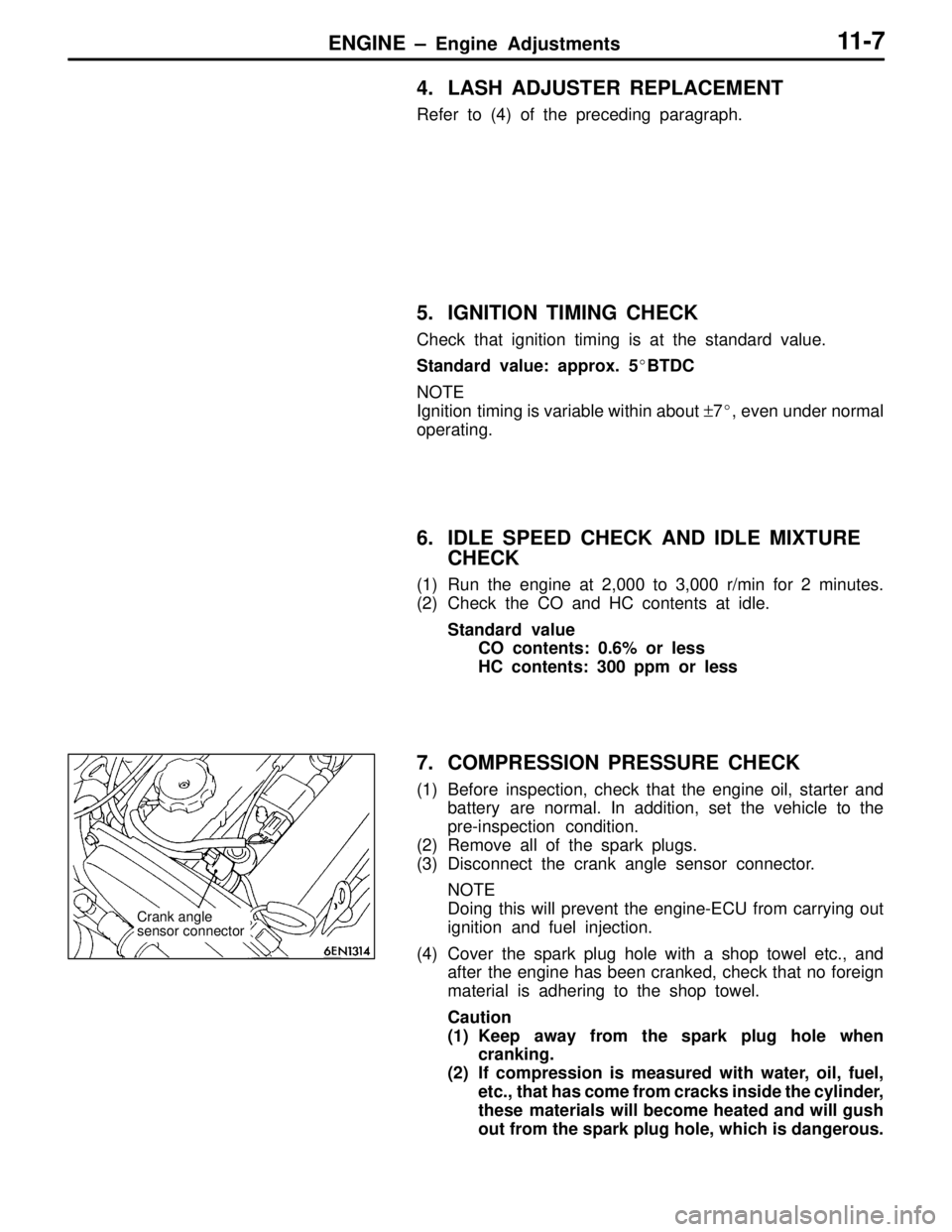
(3) Disconnect the crank angle sensor connector.
NOTE
Doing this will prevent the engine-ECU from carrying out
ignition and fuel injection.
(4) Cover the spark plug hole with a shop towel etc., and
after the engine has been cranked, check that no foreign
material is adhering to the shop towel.
Caution
(1) Keep away from the spark plug hole when
cranking.
(2) If compression is measured with water, oil, fuel,
etc., that has come from cracks inside the cylinder,
these materials will become heated and will gush
out from the spark plug hole, which is dangerous.
Crank angle
sensor connector
Page 14 of 396

ENGINE – Engine Adjustments11-8
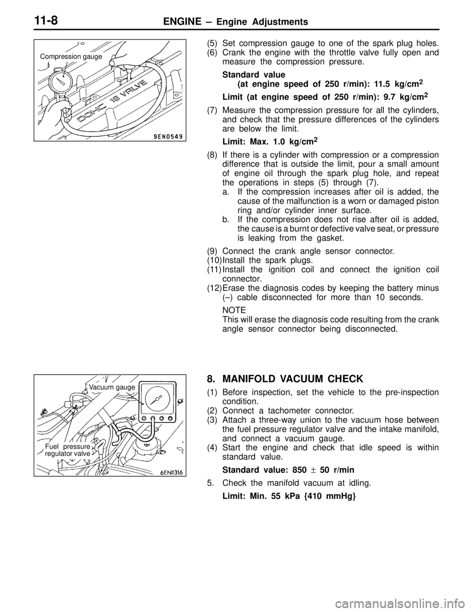
(5) Set compression gauge to one of the spark plug holes.
(6) Crank the engine with the throttle valve fully open and
measure the compression pressure.
Standard value
(at engine speed of 250 r/min): 11.5 kg/cm
2
Limit (at engine speed of 250 r/min): 9.7 kg/cm2
(7) Measure the compression pressure for all the cylinders,
and check that the pressure differences of the cylinders
are below the limit.
Limit: Max. 1.0 kg/cm
2
(8) If there is a cylinder with compression or a compression
difference that is outside the limit, pour a small amount
of engine oil through the spark plug hole, and repeat
the operations in steps (5) through (7).
a. If the compression increases after oil is added, the
cause of the malfunction is a worn or damaged piston
ring and/or cylinder inner surface.
b. If the compression does not rise after oil is added,
the cause is a burnt or defective valve seat, or pressure
is leaking from the gasket.
(9) Connect the crank angle sensor connector.
(10)Install the spark plugs.
(11) Install the ignition coil and connect the ignition coil
connector.
(12)Erase the diagnosis codes by keeping the battery minus
(–) cable disconnected for more than 10 seconds.
NOTE
This will erase the diagnosis code resulting from the crank
angle sensor connector being disconnected.
8. MANIFOLD VACUUM CHECK
(1) Before inspection, set the vehicle to the pre-inspection
condition.
(2) Connect a tachometer connector.
(3) Attach a three-way union to the vacuum hose between
the fuel pressure regulator valve and the intake manifold,
and connect a vacuum gauge.
(4) Start the engine and check that idle speed is within
standard value.
Standard value: 850 ± 50 r/min
5. Check the manifold vacuum at idling.
Limit: Min. 55 kPa {410 mmHg}
Compression gauge
Vacuum gauge
Fuel pressure
regulator valve
Page 15 of 396
ENGINE – Crankshaft Pulley11-9
CRANKSHAFT PULLEY
REMOVAL AND INSTALLATION
Pre-removal Operation
�Under Cover RemovalPost-installation Operation
�Drive Belt Tension Adjustment (Refer to P.11-4.)
�Under Cover Installation
1
2
25 {2.5}
Unit: Nm {kgf�m}
Removal steps
�A�1. Drive belt
2. Crankshaft pulley
REMOVAL SERVICE POINT
�A�DRIVE BELT REMOVAL
(1) Align the hole in the auto tensioner bracket with that
in the arm and insert a screwdriver into the holes.
(2) Remove the drive belt.
Phillips
screwdriver
Hole in arm
Auto tensioner
Hole in bracket
Page 16 of 396

ENGINE – Camshaft and Camshaft Oil Seal11-10
CAMSHAFT AND CAMSHAFT OIL SEAL
REMOVAL AND INSTALLATION
Pre-removal and Post-installation Operation
(1) Engine Coolant Draining and Refilling
(2) Air Hose C Removal and Installation
(Refer to GROUP 15 – Intercooler.)
(3) Spark Plug Cable and Ignition Coil Assembly Removal
and Installation(4) Air Pipe Removal and Installation
(Refer to GROUP 15 – Air Control Valve.)
(5) Timing Belt Removal and Installation
(Refer to P.11-21.)
22 {2.2}
Unit: Nm {kgf�m}
10 {1.0}9 {0.9}
3.4 {0.35}
20 {2.0}
88 {9.0} 12 – 15 {1.2 – 1.5}
1
53 4
6
2
14
15
17 16
13
12
11 10 9 8 7
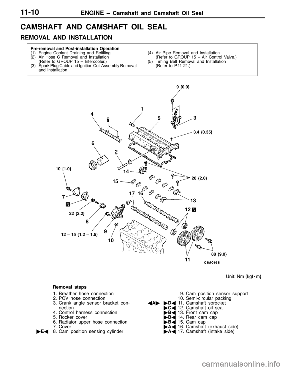
Removal steps
1. Breather hose connection
2. PCV hose connection
3. Crank angle sensor bracket con-
nection
4. Control harness connection
5. Rocker cover
6. Radiator upper hose connection
7. Cover
�E�8. Cam position sensing cylinder9. Cam position sensor support
10. Semi-circular packing
�A��D�11. Camshaft sprocket
�C�12. Camshaft oil seal
�B�13. Front cam cap
�B�14. Rear cam cap
�B�15. Cam cap
�A�16. Camshaft (exhaust side)
�A�17. Camshaft (intake side)
Page 17 of 396
ENGINE – Camshaft and Camshaft Oil Seal11-11
Grease and adhesive application points
Timing belt side
Semi-drying sealant: THREEBOND 1207D
Lip 10 mm
10 mm10 mm
Semi-drying sealant:
THREEBOND 1207FEngine oil
Semi-drying sealant: THREEBOND 1207DTiming belt side
26
φ 3 mm
REMOVAL SERVICE POINT
�A�CAMSHAFT SPROCKET REMOVAL
INSTALLATION SERVICE POINTS
�A�CAMSHAFT INSTALLATION
(1) Apply engine oil to the cams and journals of the camshaft.
(2) Mount the camshaft on the cylinder head.
Caution
Make sure that the camshaft has a unique orientation
for installation, the intake side and exhaust side. The
exhaust camshaft has a slit in the rear end face.
MB990767
MD998719
Camshaft sprocket side
Camshaft (exhaust side)Slit
Page 18 of 396
ENGINE – Camshaft and Camshaft Oil Seal11-12
�B�CAM CAP / REAR CAP / FRONT CAM CAP
INSTALLATION
(1) Locate the camshaft dowel pins as illustrated.
(2) Temporarily tighten cam cap in two to three steps, then
torque it to specification.
Tightening torque: 20 Nm {2.0 kgf�m}
�C�CAMSHAFT OIL SEAL INSTALLATION
(1) Apply engine oil to the entire periphery of the oil seal
lip.
(2) Pressfit the oil seal as shown.
�D�CAMSHAFT SPROCKET INSTALLATION
As you did during removal, secure the camshaft sprocket
with the special tool and tighten bolt to specification.
Tightening torque: 88 Nm {9.0 kgf�m}
�E�CAM POSITION SENSING CYLINDER
Install the cam position sensing cylinder so that the ID paint
on the cam position sensing cylinder is 90� with respect to
the camshaft dowel pin as shown.
Intake side Approx. 12�Dowel pin
Exhaust side
MD998713
ID paintDowel pin
90�
Page 19 of 396
ENGINE – Oil Pan11-13
OIL PAN
REMOVAL AND INSTALLATION
Pre-removal and Post-installation Operation
(1) Under Cover Removal and Installation
(2) Front Exhaust Pipe Removal and Installation
(Refer to GROUP 15.)(3) Oil Level Gauge Removal and Installation
(4) Engine Oil Draining and Supplying
A: 6 × 8 mm
B: 6 × 10 mm
Identification of bolt location
Semi-drying sealant: THREEBOND 1207Dφ 4 mm
Bolt
hole
Groove
8
AB
B 8
B
B B
3
78
6 451 2
39 {4.0}
39 – 44 {4.0 – 4.5}7 {0.7}26 {2.6}30 {3.1} 9 {0.9}
Washer
assembled bolt
9 {0.9}
Flange bolt
10 {1.0}
Unit: Nm {kgf�m}
Removal steps
1. Starter
2. Oil return pipe
�B�3. Oil return pipe gasket
4. Engine oil cooler return pipe5. Bell housing cover
6. Drain plug
�A�7. Drain plug gasket
�A�8. Oil pan
Page 20 of 396
ENGINE – Oil Pan11-14
REMOVAL SERVICE POINT
�A�OIL PAN REMOVAL
INSTALLATION SERVICE POINTS
�A�DRAIN PLUG GASKET INSTALLATION
Install the drain plug gasket in the direction so that it faces
as shown in the illustration.
�B�OIL RETURN PIPE GASKET INSTALLATION
Install the gasket with the printed portion toward the oil pan.
MD998727MD998727
Drain plug gasket
Oil pan side
GasketPrinted portion