Page 59 of 396

MPI – Troubleshooting13-16
Code No. 64 Alternator FR Terminal SystemProbable cause
Range of Check
�Engine speed is approximately 50 r/min or more.
Set conditions
�Input voltage at the alternator FR terminal is 4.5 V or more for 20 seconds.�Open circuit in alternator FR terminal circuit
�Malfunction of the engine-ECU.
OK
Replace the alternator.
NG
Check the harness wire between
the engine-ECU and alternator
connector.NG
Repair
OK
Check trouble symptom.
Measure at the alternator connec-
tor
�Connect the connector.
(Use test harness MB991519.)
�Voltage between 4 (blue clip)
and earth
(Engine: Idling)
(Radiator fan: Stopped)
(Headlamp: OFF → ON)
(Brake lamp: OFF → ON)
(Rear defogger switch: OFF
→ ON)
OK:Voltage drops by 0.2 to
3.5 V.NGMeasure at the alternator connec-
tor A-05.
�Disconnect the connector, and
measure at the harness side.
�Voltage between 4 and earth
(Ignition switch: ON)
OK:4.8 – 5.2 VNGCheck the following connec-
tors:
B-60, A-88NG
Repair
OK
Check trouble symptom.
NG
Check the harness wire between
the engine-ECU and alternator
connector.NG
Repair
OK
Replace the engine-ECU.
OK
Check the following connector:
A-05NG
Repair
OK
Replace the engine-ECU.
Page 76 of 396

MPI – On-vehicle Service13-33
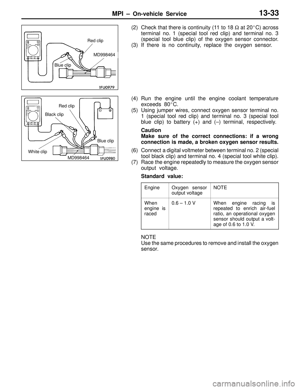
(2) Check that there is continuity (11 to 18 Ω at 20�C) across
terminal no. 1 (special tool red clip) and terminal no. 3
(special tool blue clip) of the oxygen sensor connector.
(3) If there is no continuity, replace the oxygen sensor.
(4) Run the engine until the engine coolant temperature
exceeds 80�C.
(5) Using jumper wires, connect oxygen sensor terminal no.
1 (special tool red clip) and terminal no. 3 (special tool
blue clip) to battery (+) and (–) terminal, respectively.
Caution
Make sure of the correct connections: if a wrong
connection is made, a broken oxygen sensor results.
(6) Connect a digital voltmeter between terminal no. 2 (special
tool black clip) and terminal no. 4 (special tool white clip).
(7) Race the engine repeatedly to measure the oxygen sensor
output voltage.
Standard value:
EngineOxygen sensor
output voltageNOTE
When
engine is
raced0.6 – 1.0 VWhen engine racing is
repeated to enrich air-fuel
ratio, an operational oxygen
sensor should output a volt-
age of 0.6 to 1.0 V.
NOTE
Use the same procedures to remove and install the oxygen
sensor.
Red clip
Blue clip
MD998464
Red clip
Blue clip
MD998464 Black clip
White clip
Page 111 of 396
ENGINE EMISSION CONTROL – Emission Control System 17-3
VACUUM HOSE PIPING CIRCUIT DIAGRAM
Fuel pressure
control valve
Surge tank
Secondary air
control solenoid
valveBlue White
Canister
Check
valve
Throttle body
Fuel
pressure
regulatorWastegate
solenoid
valve
Secondary
air valve
Bypass
valve
Front of vehicle
Wastegate
actuator Vacuum hose color
B: Black
L: Blue
R: Red
W: White
Y: Yellow
CANISTER
REMOVAL AND INSTALLATION
Pre-removal and Post-installation Operation
�Air Cleaner Removal and Installation
2
1
3
4
Removal steps
1. Vapor hose
2. Purge hose
3. Canister
4. Canister bracket
Page 136 of 396

Lubricants / Snap Rings, Spacers
and Thrust Plates for Adjustment MANUAL TRANSMISSION
OVERHAUL –22B-6
LUBRICANTS
TRANSMISSION
ItemsSpecified lubricants
Drive shaft oil seal lip areaDIA QUEEN MULTI-GEAR OIL 75W/85W
(Transmission oil)
Input shaft oil seal lip area
(Transmission oil)
Control shaft oil seal lip area
Select lever shoeMOLYWHITE TA No.1 or No.2
TRANSFER
ItemsSpecified lubricants
Drive shaft oil seal lip areaDIA QUEEN MULTI-GEAR OIL 75W/85W
(Transmission oil)
Front differential oil seal lip area
(Transmission oil)
O-rings
SNAP RINGS, SPACERS AND THRUST PLATES FOR
ADJUSTMENT
Part nameThickness mmIdentification symbolPart No.
Spacer
(For adj stment of inp t shaft end pla )
1.3434MD723600
(For adjustment of input shaft end play)1.4343MD723603
1.5252MD723606
1.6161MD723609
1.7070MD756760
1.7979MD756763
Snap ring
(For adj stment of inp t shaft front bearing
1.43Green (2)MD746708
(For adjustment of input shaft front bearing
clearance)1.51White (2)MD746709
1.59Yellow (2)MD746710
Snap ring
(For adj stment of inp t shaft rear bearing
1.44NoneMD746602
(For adjustment of input shaft rear bearing
clearance)1.51BlueMD746603
1.58BrownMD746604
Page 138 of 396

Snap Rings, Spacers and Thrust Plates
for Adjustment MANUAL TRANSMISSION
OVERHAUL –22B-8
Part namePart No. Identification symbol Thickness mm
Snap ring
(For adj stment of o tp t shaft bearing clear
1.36YellowMD748449
(For adjustment of output shaft bearing clear-
ance)1.40GreenMD748450
1.44NoneMD746602
1.48BlackMD748451
1.51BlueMD746603
1.55WhiteMD748452
1.58BrownMD746604
1.63OrangeMD748453
1.68BlueMD748454
Snap ring
(For adj stment of o tp t shaft 3rd speed gear
2.81NoneMD746594
(For adjustment of output shaft 3rd speed gear
clearance)2.85BlueMD746595
2.89BrownMD746596
2.93YellowMD746597
2.97GreenMD746598
3.01BlackMD746599
3.05WhiteMD746600
3.09OrangeMD746601
Spacer
(For adj stment of center differential case
0.7474MD727660
(For adjustment of center differential case
preload)0.7777MD754476p
0.8080MD727661
0.8383MD720937
0.8686MD720938
0.8989MD720939
0.9292MD720940
0.9595MD720941
0.9898MD720942
1.0101MD720943
1.0404MD720944
1.0707MD720945
1.10JMD710454
1.13DMD700270
1.16KMD710455