1998 JAGUAR X308 ignition switch
[x] Cancel search: ignition switchPage 1598 of 2490
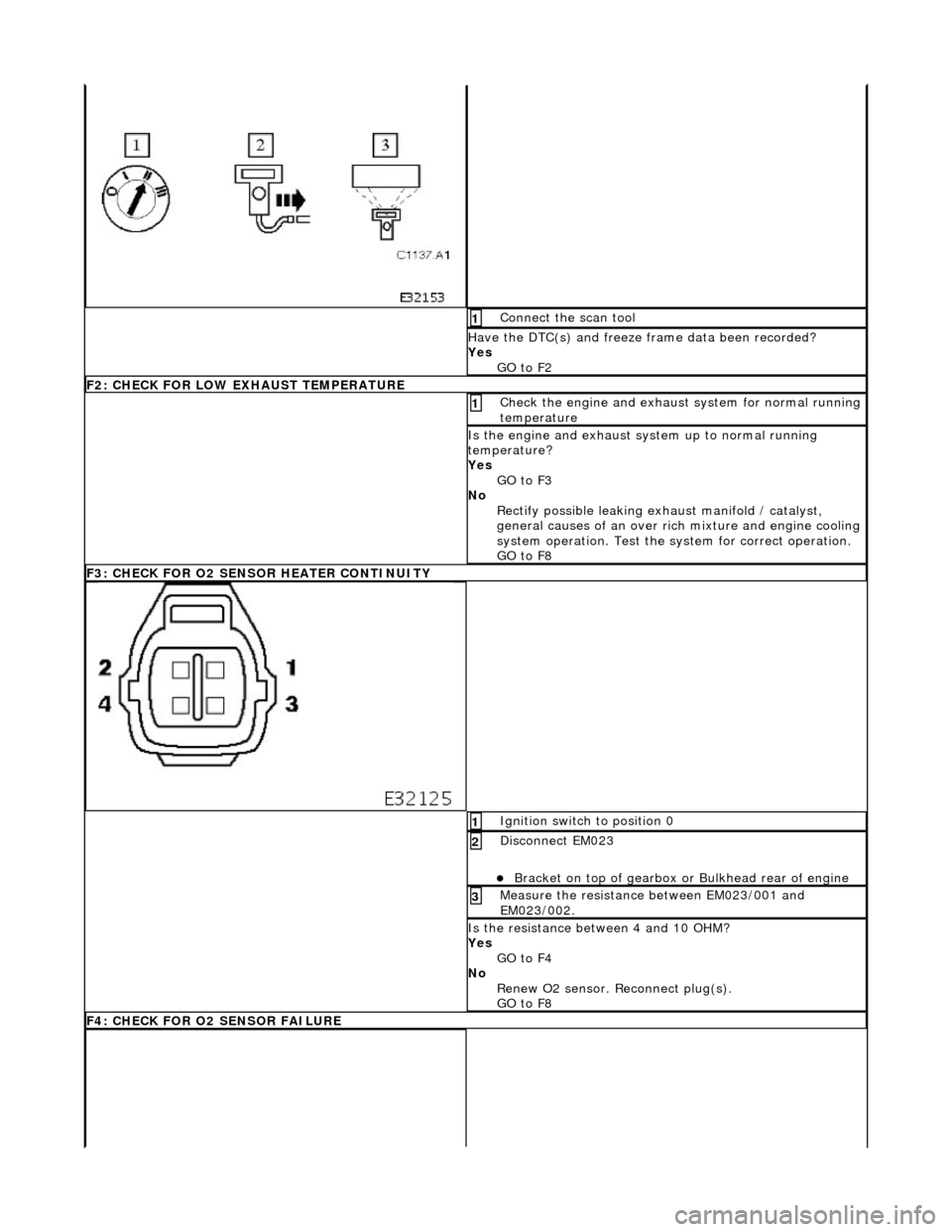
Connect the scan tool 1
Have the DTC(s) and freeze frame data been recorded?
Yes GO to F2
F2: CHECK FOR LOW EXHAUST TEMPERATURE
Check the engine and exhaust system for normal running
temperature 1
Is the engine and exhaust sy stem up to normal running
temperature?
Yes GO to F3
No Rectify possible leaking exhaust manifold / catalyst,
general causes of an over ri ch mixture and engine cooling
system operation. Test the sy stem for correct operation.
GO to F8
F3: CHECK FOR O2 SENSOR HEATER CONTINUITY
Ignition switch to position 0 1
Disconnect EM023
Bracket on top of gearbox or Bulkhead rear of engine
2
Measure the resistance between EM023/001 and
EM023/002. 3
Is the resistance between 4 and 10 OHM?
Yes
GO to F4
No Renew O2 sensor. Reconnect plug(s).
GO to F8
F4: CHECK FOR O2 SENSOR FAILURE
Page 1608 of 2490
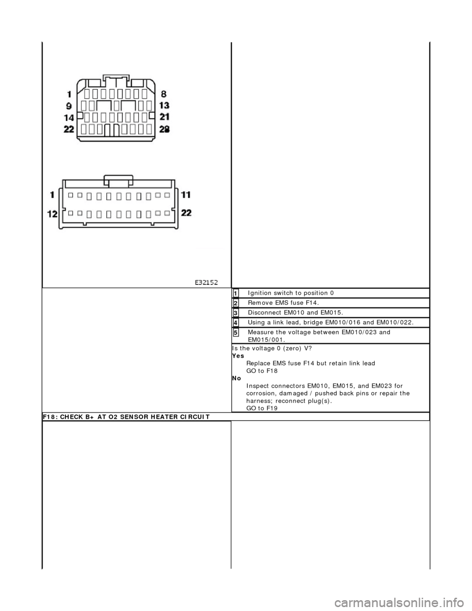
Ignition switch to position 0 1
Remove EMS fuse F14. 2
Disconnect EM010 and EM015. 3
Using a link lead, bridge EM010/016 and EM010/022. 4
Measure the voltage between EM010/023 and
EM015/001. 5
Is the voltage 0 (zero) V?
Yes Replace EMS fuse F14 but retain link lead
GO to F18
No Inspect connectors EM010, EM015, and EM023 for
corrosion, damaged / pushed back pins or repair the
harness; reconnect plug(s).
GO to F19
F18: CHECK B+ AT O2 SENSOR HEATER CIRCUIT
Page 1690 of 2490
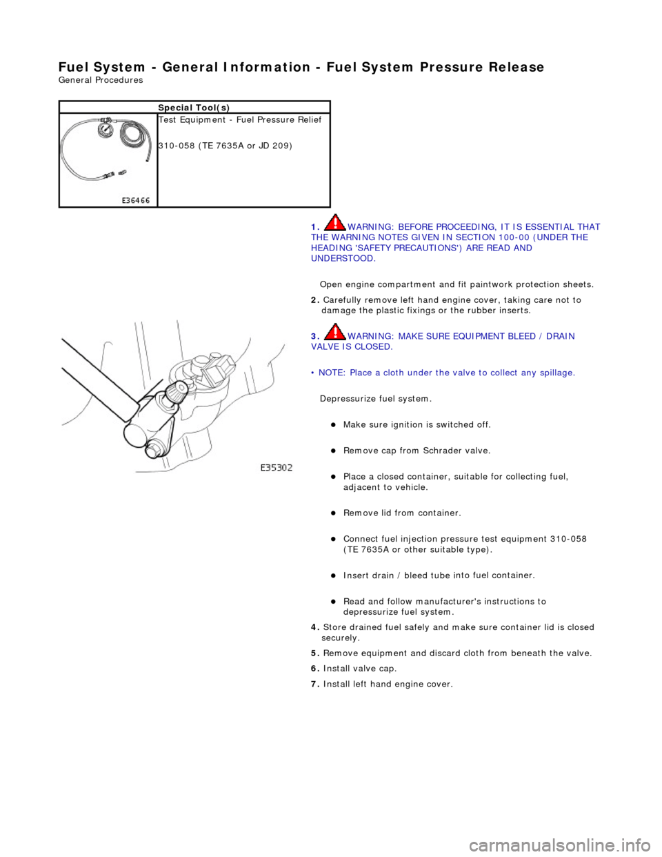
Fuel System - General Information - Fuel System Pressure Rele
ase
Gen
e
ral Procedures
S p
ecial Tool(s)
Tes
t
Equipment - Fuel Pressure Relief
310-058 (TE 7635A or JD 209)
1. WARNING: BEFORE PROCEEDING, IT IS ESSENTIAL THAT
THE WARNING NOTES GIVEN IN SECTION 100-00 (UNDER THE
HEADING 'SAFETY PRECAUTIONS') ARE READ AND
UNDERSTOOD.
Open engine compartment and fi t paintwork protection sheets.
2. Carefull
y remove left
hand engine cover, taking care not to
damage the plasti c fixings or the rubber inserts.
3. WA
RNING: MAKE SURE EQUIPMENT BLEED / DRAIN
VALVE IS CLOSED.
• NOTE: Place a cloth under the valve to collect any spillage.
Depressurize fuel system.
Make sure ignition i s
switched off.
R
e
move cap from Schrader valve.
Pla
c
e a closed container, su
itable for collecting fuel,
adjacent to vehicle.
R e
move lid from container.
Conne
ct
fuel injection pressu
re test equipment 310-058
(TE 7635A or other suitable type).
Insert drain / bleed tu be i
nto fuel container.
R
e
ad and follow manufacturer's instructions to
depressurize fuel system.
4. Store drained f u
el safely and make
sure container lid is closed
securely.
5. Remove equipment and discard cloth from beneath the valve.
6. Install valve cap.
7. Install left hand engine cover.
Page 1691 of 2490
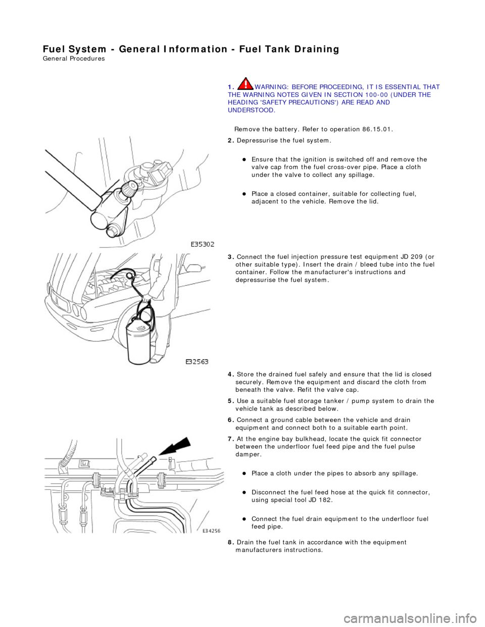
Fuel System - Gener
al Information - Fuel Tank Draining
Gen
eral Procedures
1.
WARNING: BEFORE PROCEEDING, IT IS ESSENTIAL THAT
THE WARNING NOTES GIVEN IN SECTION 100-00 (UNDER THE
HEADING 'SAFETY PRECAUTIONS') ARE READ AND
UNDERSTOOD.
Remove the battery. Refer to operation 86.15.01.
2. De
pressurise the fuel system.
E
nsure that the ignition is
switched off and remove the
valve cap from the fuel cross-over pipe. Place a cloth
under the valve to collect any spillage.
Pla
ce a closed container, su
itable for collecting fuel,
adjacent to the vehicle. Remove the lid.
3. Conne
ct the fuel injection pressu
re test equipment JD 209 (or
other suitable type). Insert the drain / bleed tube into the fuel
container. Follow the manufa cturer's instructions and
depressurise the fuel system.
4. Store the drained fuel safely and ensure that the lid is closed
securely. Remove the equipmen t and discard the cloth from
beneath the valve. Refit the valve cap.
5. Use a suitable fuel storage tank er / pump system to drain the
vehicle tank as described below.
6. Connect a ground cable betw een the vehicle and drain
equipment and connect both to a suitable earth point.
7. At the engine bay bulkhead, lo cate the quick fit connecto
r
between the underfloor fuel feed pipe and the fuel pulse
damper.
Pla
ce a cloth under the pipes
to absorb any spillage.
D
isconnect the fuel feed hose
at the quick fit connector,
using special tool JD 182.
Conne
ct the fuel drain equipment to the underfloor fuel
feed pipe.
8. Drain the fuel tank in accordance with the equipment
manufacturers instructions.
Page 1693 of 2490
Filler Cap and P
ipe
The fuel
filler cap with bayonet-type fixi
ng is located beneath a remote-release sp ring-latched lid on the rear saddle panel
on the left-hand-side of the vehicle.
Fuel Pum
p
The fu
el pump(s) is energized by an ECM co
ntrolled relay. Fuel is drawn by this pu mp and supplied to the fuel injectors via
the fuel line, filter and fuel rails.
Servicing of the fuel pump re quires fuel tank removal.
Ev
aporative Loss Flange Assembly
The evaporative-loss flan
ge asse
mbly is mounted centrally on top of the tank. The flange assembly consists of a removeable
steel cap which mounts the evaporative emissions system vapor outlet valves and, if applicable, a pressure sensor. The
external electrical supply to th e fuel pump(s) is also made via a connector on the flange.
The flange assembly is fixed to the tank by a locking ring which is turned usin g special tool JD-174. A seal is fitted between
the flange assembly and the tank. Three di fferent flange assemblies are applicable according to the evaporative emission
system fitted to the vehicle. The fl ange size and fixing are identical fo r the three systems, as described.
Removal of the evaporative flange assembly is necessary to gain access to th e fuel pump(s) and other internal components.
To remove the evaporative fl ange assembly the fuel tank must first be removed.
The evaporative flange variant assemblies are described, together with service information, in Section 303-13.
Fuel R
eturn
Excess fuel
is directed back to
the fuel tank via a return line.
Fuel Pum
p Relay
The
fuel pump relay,
under control of the ECM, switches power to the fuel pump motor.
I
nertia Fuel Shutoff (IFS) Switch
The IF
S switch is located in the right-hand
side footwell behind the footboard carpet . When activated the switch isolates the
ignition system and fuel pump, releases any locked doors and disables unnecessary electrical systems. The system can be
reset by pressing down the flexible cover on the top of the switch.
• NOTE: The doors will not unlock if the IFS switch is tripped when the ignition switch is in position '0'.
Page 1743 of 2490
Accelerati
on Control - Accelerator Cable Adjustment
Gen
eral Procedures
1.
Load the Approved Jaguar Diagno stic System with power train
data logger.
2. Connect the Approved Jaguar Diag nostic System to the vehicle.
3. W
ith 'Disable Network Integrity Test - YES/ NO' displayed on
the screen select YES.
4. With new menu displayed on the screen, select ' Engine
Management'.
5. Turn the ignition to ON.
R
emove any previously selected data logger parameters.
6. On data logger select PPS11 an d PPS2 (Pedal demand sensors
1 and 2).
7. On Sedan models only, remove the bulkhead covers on both
sides and the engine compartment rear cover.
8. Cut, remove and discard the ra tchet strap which retains the
throttle cable to the abutment bracket.
9. Ensure there is no tension on the throttle cable by releasing
the throttle cable adjustment nut from the abutment bracket.
10. Record the voltages for both sensors, PPS11 and PPS2.
11. Partially insert the throttle cable adjustment nut into the
abutment bracket.
12. Recheck the voltages for both sensors, PPS11 and PPS2.
13. Where the voltages at step 12 are higher than the voltages
taken at step 10, contin ue to step 15 below.
14. Where the voltages at step 12 are the same as the voltages
taken at step 10, contin ue to step 16 below.
15. Rotate the adjustment nut clockwise (as viewed from the
front of the vehicle) until the same voltages are indicated as in
step 10. Continue to turn thro ugh a part revolution until the
sides of the nut are vertical. Tu rn through a further 90 degrees,
then fully insert the nut into the abutment bracket.
16. Rotate the adjustment nut anti-clockwise (as viewed from the
front of the vehicle) until the indicated voltage starts to
increase. Then rotate the nut clockwise through a part
revolution until the sides are ve rtical. Turn through a further 90
degrees, then fully insert the nut into the abutment bracket.
17. Fit a new ratchet strap to secure the throttle cable adjusting
nut to the abutment bracket.
18. Operate the throttle pedal through 20 full cycles to settle the
cable. Check the voltages now shown, remain the same as in
steps 15 and 16.
19. Check and where necessary adjust the kickdown switch. For
additional information, refer to Section 307
-05A Automatic Transmissi
on/Transaxle External Controls
Sectio
n
307
-05
B
Au
tomatic Transmission/Tra
nsaxle External Controls
.
20
.
On Sedan models only, refit the engine compartment rear
cover and the bulkhead co vers on both sides.
21. Switch the ignition OFF and disconnect the Approved Jaguar
Diagnostic System.
Page 1745 of 2490
Pinpoint test
s
re
sistance
ACCEL/DECEL
swi
tch failure
P0569Speed
control
DECEL/SET
(SET-) switch ON fault
Speed
control switches internal steering wheel
short circuit to ground
S
teering wheel cassette
reel short circuit to
ground
Cassette reel
to ECM ci
rcuit short circuit to
ground
DEC
EL/SET
switch failure (stuck ON)
Fo
r
DECEL/SET (SET-) switch
circuit tests,GO to Pinpoint Test D.
P0570Speed
control
ACCEL/SET
(SET+) switch ON fault
Speed
control switches internal steering wheel
short circuit to ground
S
teering wheel cassette
reel short circuit to
ground
Cassette reel
to ECM ci
rcuit short circuit to
ground
ACC
EL/SET
switch failure (stuck ON)
Fo
r
ACCEL/SET circuit tests,GO
to Pinpoint Test E.
P1571Brake sw
itch malfunction
Brake sw
itch to ECM circuit open circuit, short
circuit to ground, high resistance
Brake sw
itch ignition switched ground circuit
open circuit
Brake sw
itch failure
Brake ca
ncel switch to
ECM circuit open circuit,
short circuit to ground, high resistance
Brake ca
ncel switch to speed control switch
circuit open circuit, shor t circuit to ground, high
resistance
Brake ca
ncel switch ignition switched power
supply open circuit
Brake ca
ncel switch failure
Spe
ed control switch failure
For brake swi
tch circuit tests,GO
to Pinpoint Test F.
P
INPOINT TEST A : DTC P0566; SPEED
CONTROL CANCEL SWITCH ON FAULT
WAR
NING: Where tests involve the removal of the steering
wheel, and/or disconnection of air bag connectors, the
procedure for disarming air bags must be followed,
REFER to: Air Bag Supplemental Re straint System (SRS)
(501-20B Supplemental Restra
int System, Description and
Operation).
TE
ST
CONDITIONS
D
ETAILS/RESULTS/ACTIONS
A1: CHECK
THE SPEED CONTROL SWITCHPACK IN
TERNAL CIRCUITS FOR SHORT TO GROUND
Di
sconnect the battery negative terminal.
1
Di
sconnect the speed control switch
pack electrical connector, SW02.
2
R
econnect the battery negative terminal.
3
Meas
ure the resistance between SW
02, pin 06 (BO) and GROUND.
4
Meas
ure the resistance between SW
02, pin 03 (SG) and GROUND.
5
Is either resi
stance
less than 10,000 ohms?
Yes REPAIR the short circuit. For addi tional information, refer to the wiring diagrams. CLEAR the DTC.
TEST the system for normal operation.
No GO to A2
.
A2: CHECK
THE SPEED CONTROL CASSE
TTE REEL FOR SHORT TO GROUND
Di
sconnect the battery negative terminal.
1
D
isconnect the ECM electrical connector, EM11.
2
R
econnect the battery negative terminal.
3
M
easure the resistance between SW02, pin 06 (at the cassette reel side of the connector) and
GROUND.
4
M
easure the resistance between SW02, pin 03 (at the cassette reel side of the connector) and
GROUND.
5
Is either resi
stance
less than 10,000 ohms?
Yes REPAIR the short circuit. For addi tional information, refer to the wiring diagrams. CLEAR the DTC.
TEST the system for normal operation.
Page 1749 of 2490
Di
sconnect the speed control switch
pack electrical connector, SW02.
1
Meas
ure the resistance between SW
02, pin 06 (BO) and GROUND.
2
Meas
ure the resistance between SW
02, pin 04 (SR) and GROUND.
3
Is either resi
stance
less than 10,000 ohms?
Yes REPAIR the short circuit. For addi tional information, refer to the wiring diagrams. CLEAR the DTC.
TEST the system for normal operation.
No GO to E2
.
E2
: CHECK THE SPEED CONTROL CASSE
TTE REEL FOR SHORT TO GROUND
M
easure the resistance between SW02, pin 06 (at the cassette reel side of the connector) and
GROUND.
1
M
easure the resistance between SW02, pin 04 (at the cassette reel side of the connector) and
GROUND.
2
Is either resi
stance
less than 10,000 ohms?
Yes REPAIR the short circuit. For addi tional information, refer to the wiring diagrams. CLEAR the DTC.
TEST the system for normal operation.
No GO to E3
.
E3
: CHECK THE SPEED CONTROL
ACCEL/SET+ SWITCH ACTION
Meas
ure the resistance between SW02,
pin 06 (BO) and SW02, pin 04 (SR).
1
Op
erate the cruise control
ACCEL/SET+ switch.
2
D
oes the resistance
vary by 430 ohms?
Yes Recheck DTCs. No short found. Po ssible intermittent fault. CLEAR the DTC. TEST the system for
normal operation.
No INSTALL a new speed control switchpack. CLEAR the DTC. TEST the system for normal operation.
P
INPOINT TEST F : DTC P1571;
BRAKE SWITCH MALFUNCTION
WAR
NING: Where tests involve the removal of the steering
wheel, and/or disconnection of air bag connectors, the
procedure for disarming air bags must be followed,
REFER to: Air Bag Supplemental Re straint System (SRS)
(501-20B Supplemental Restra
int System, Description and
Operation).
TE
ST
CONDITIONS
D
ETAILS/RESULTS/ACTIONS
F1: CHECK THE BRAKE
SWITCH TO
ECM CIRCUIT FOR HIGH RESISTANCE
Di
sconnect the battery negative terminal.
1
Di
sconnect the brake switch electrical connector, AC24.
2
D
isconnect the ECM electrical connector, EM10.
3
Meas
ure the resistance between AC24,
pin 01 (US) and EM10, pin 10 (US).
4
Is th
e resistance greater than 5 ohms?
Yes REPAIR the high resistance circui t. For additional information, refer to the wiring diagrams. CLEAR
the DTC. TEST the system for normal operation.
No GO to F2
.
F2: CHECK THE BRAKE
SWITCH TO ECM
CIRCUIT FOR SHORT TO HIGH VOLTAGE
R
econnect the battery negative terminal.
1
Turn the ignition swi
tch to the ON
position.
2
M
easure the voltage between AC24, pin 01 (US) and GROUND.
3
Is th
e voltage greater than 3 volts?
Yes REPAIR the short circuit. For addi tional information, refer to the wiring diagrams. CLEAR the DTC.
TEST the system for normal operation.
No GO to F3
.
F3: CHECK THE BRAKE
SWITCH TO
ECM CIRCUIT FOR SHORT TO GROUND
Turn the ignition swi
tch to the OFF
position.
1
Meas
ure the resistance between AC24, pin 01 (US) and GROUND.
2