1998 JAGUAR X308 ignition switch
[x] Cancel search: ignition switchPage 2271 of 2490
Instrument Panel and Console - Steering Column Lower Shroud
Removal and Installation
Removal
Installation
1.
Move driver seat fully rearward.
2. Remove battery cover and disconnect ground cable from
battery terminal.Refer to 86.15.19.
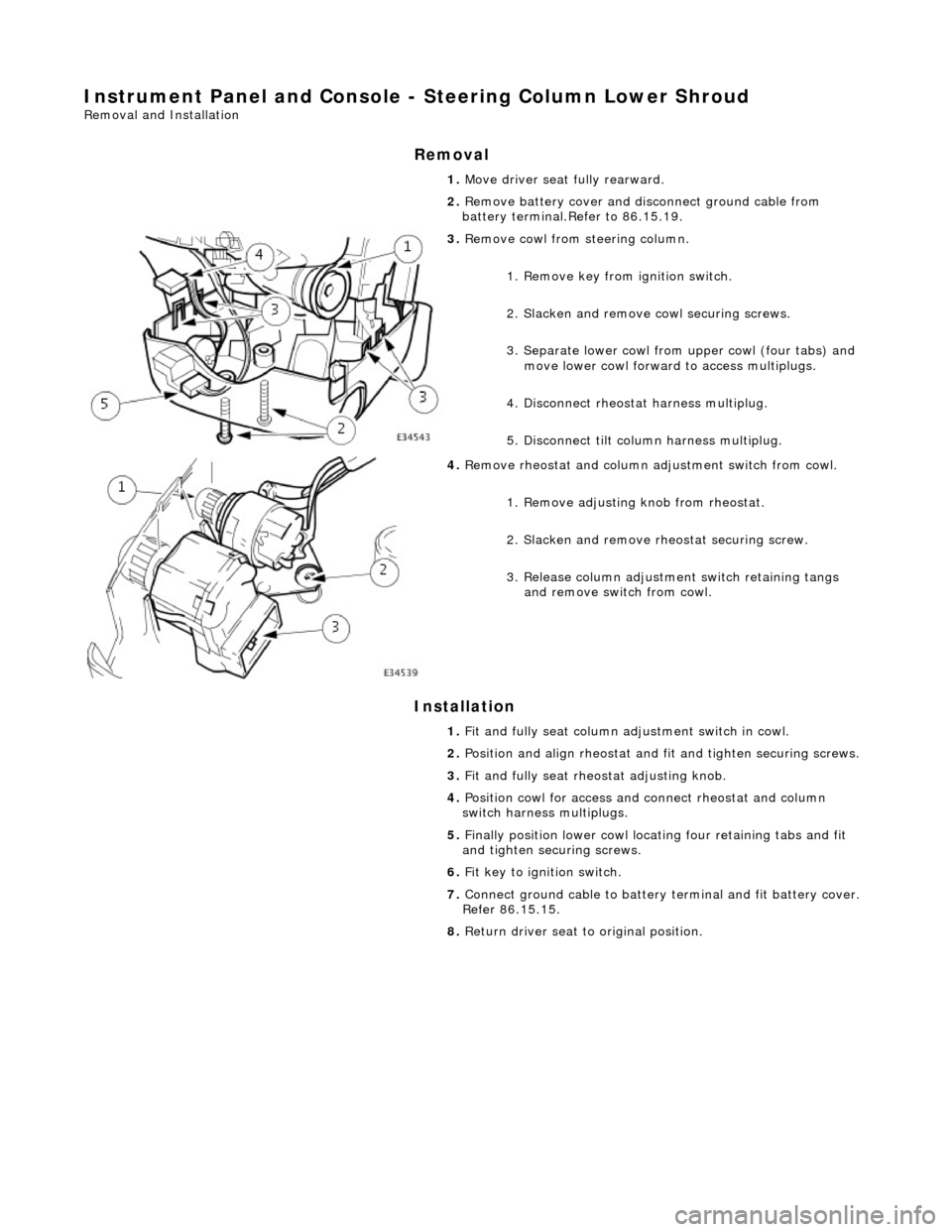
3. Remove cowl from steering column.
1. Remove key from ignition switch.
2. Slacken and remove cowl securing screws.
3. Separate lower cowl from upper cowl (four tabs) and move lower cowl forward to access multiplugs.
4. Disconnect rheostat harness multiplug.
5. Disconnect tilt column harness multiplug.
4. Remove rheostat and column adjustment switch from cowl.
1. Remove adjusting knob from rheostat.
2. Slacken and remove rh eostat securing screw.
3. Release column adjustment switch retaining tangs and remove switch from cowl.
1. Fit and fully seat column ad justment switch in cowl.
2. Position and align rheostat and fit and tighten securing screws.
3. Fit and fully seat rheo stat adjusting knob.
4. Position cowl for access and connect rheostat and column
switch harness multiplugs.
5. Finally position lower cowl locating four retaining tabs and fit
and tighten securing screws.
6. Fit key to ignition switch.
7. Connect ground cable to battery terminal and fit battery cover.
Refer 86.15.15.
8. Return driver seat to original position.
Page 2273 of 2490
Handles, Locks, Latches and Entry Systems - Handles, Locks, Latches and
Entry Systems
Description and Operation
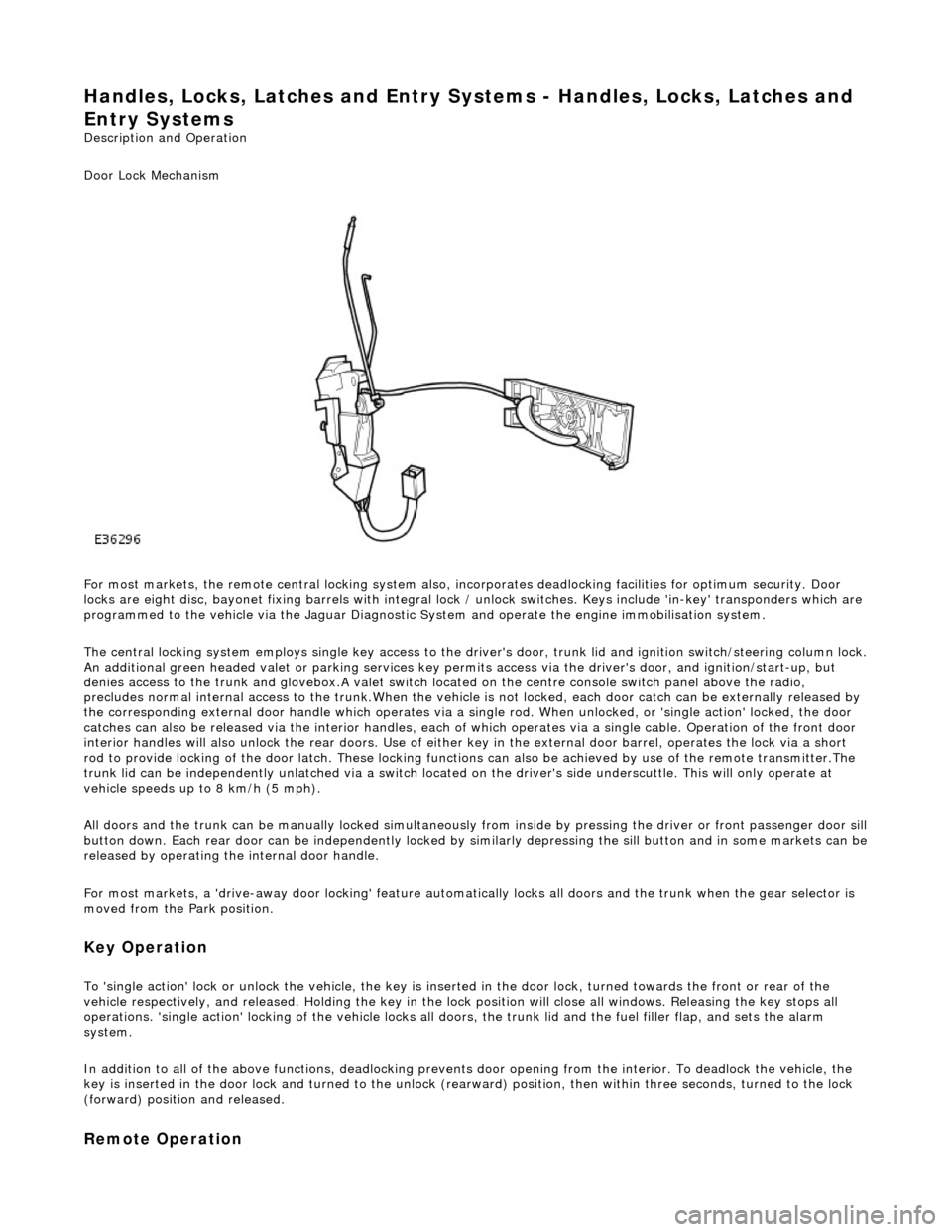
Door Lock Mechanism
For most markets, the remote central locking system also, in corporates deadlocking facilities for optimum security. Door
locks are eight disc, bayonet fixing barrels with integral lock / unlock switches. Keys include 'in-key' transponders which are
programmed to the vehicle via the Jaguar Diagnostic Sy stem and operate the engine immobilisation system.
The central locking system employs single key access to the driv er's door, trunk lid and ignition switch/steering column lock.
An additional green headed valet or park ing services key permits access via the driver's door, and ignition/start-up, but
denies access to the trunk and glovebox.A valet switch located on the centre console switch panel above the radio,
precludes normal internal access to the trunk.When the vehicle is not locked, each door catch can be externally released by
the corresponding external door handle which operates via a si ngle rod. When unlocked, or 'single action' locked, the door
catches can also be released via the interior handles, each of which operates via a single cable. Operation of the front door
interior handles will also unlock the rear doors. Use of either key in the external door barrel, operates the lock via a short
rod to provide locking of the door latch. These locking functions can also be achieved by use of the remote transmitter.The
trunk lid can be independently unlatched via a switch located on the driver's side underscuttle. This will only operate at
vehicle speeds up to 8 km/h (5 mph).
All doors and the trunk can be manually lock ed simultaneously from inside by pressing the driver or front passenger door sill
button down. Each rear door can be independently locked by si milarly depressing the sill button and in some markets can be released by operating the internal door handle.
For most markets, a 'drive-away door locking' feature automati cally locks all doors and the trunk when the gear selector is
moved from the Park position.
Key Operation
To 'single action' lock or unlock the vehicle, the key is inserted in the door lock , turned towards the front or rear of the
vehicle respectively, and released. Holding the key in the lock position will close all windows. Releasing the key stops all
operations. 'single action' locking of the vehicle locks all doors, the trunk lid and the fuel filler flap, and sets the alarm
system.
In addition to all of the above functions, deadlocking prevents door opening from th e interior. To deadlock the vehicle, the
key is inserted in the door lock and turned to the unlock (rearw ard) position, then within three seconds, turned to the lock
(forward) position and released.
Remote Operation
Page 2307 of 2490
cooling duct.
The windshield washer is operated by pressing the button at the end of the wiper control stalk switch. Pressing and
releasing the button operates the washer for 1 to 1.4 seconds and the wiper completes three sweeps. An optional drip wipe
function adds a further sweep of the wiper after a 4 second delay, to clear residual fluid from the windshield. If the button is
held depressed, the washer and wiper will operate continuous ly for up to 20 seconds. When the button is released, the
wiper will again complete three further sweeps.
Headlamp Powerwash
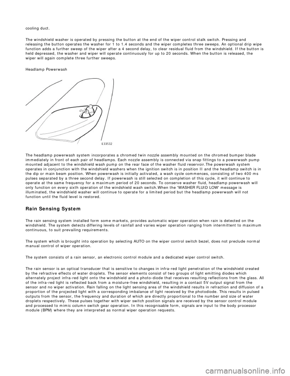
The headlamp powerwash system incorporates a chromed twin nozzle assembly mounted on the chromed bumper blade
immediately in front of each pair of he adlamps. Each nozzle assembly is connected via snap fittings to a powerwash pump
mounted adjacent to the windshield wash pump on the rear face of the washer fluid reservoir.The powerwash system
operates in conjunction with the windshield washers when the ignition switch is in position II and the headlamp switch is in
the dip or main beam position. When powerwash is initially activated, a wash cycle commences, consisting of two 400 ms
pulses separated by a three second delay. If powerwash is still selected on completion of this cycle, it will continue to
operate at the same frequency for a maximum period of 20 se conds. To conserve washer fluid, headlamp powerwash will
only function on every sixth operation of the windshie ld wash switch.When the 'WASHER FLUID LOW' message is
illuminated, the windshield washer will continue to operat e for a limited period but the headlamp powerwash will not
function until the fluid level is restored.
Rain Sensing System
The rain sensing system installed form so me markets, provides automatic wiper operation when rain is detected on the
windshield. The system detects differing le vels of rainfall and varies wiper operation ranging from intermittent to maximum
continuous, to suit prevailing requirements.
The system which is brought into operation by selecting AUTO on the wiper control switch bezel, does not preclude normal
manual control of wiper operation.
The system consists of a rain sensor, an electronic control module and a dedicated wiper control switch.
The rain sensor is an optical transducer that is sensitive to changes in infra-red light penetration of the windshield created
by the refractive effects of water drople ts. The sensor elements consist of two groups of light emitting diodes which
alternately project infra-red light onto th e windshield and a photo-diode that receiv es resulting reflections from the glass. A ll
of the infra-red light is reflected back from a moisture-free windshield, resulting in a contact 5V output signal from the
sensor and no wiper activation. Rain falling on the light sensing area of the wi ndshield results in refraction and diffusion of a
proportion of the projected light with a corresponding imbalance of light received by the photodiode. This results in pulsed
outputs from the sensor, the frequency and duration of which are directly proportional to the number and size of water
droplets respectively. These pulses together with wiper switch position signals are received by the sensor control module
and processed to mimic column switch gear operation. In this recognisable form, signals are input to the body processor
module (BPM) where they are interprete d as normal wiper operation requests.
Page 2330 of 2490
Roof Opening Panel - Roof Opening Panel Alignment
General Procedures
1.
Remove sliding roof trim panel for access. Refer to 76.82.19.
2. Turn ignition switch to position II.
3. Fully close sliding roof.
4. Turn ignition switch to po sition O and remove key.
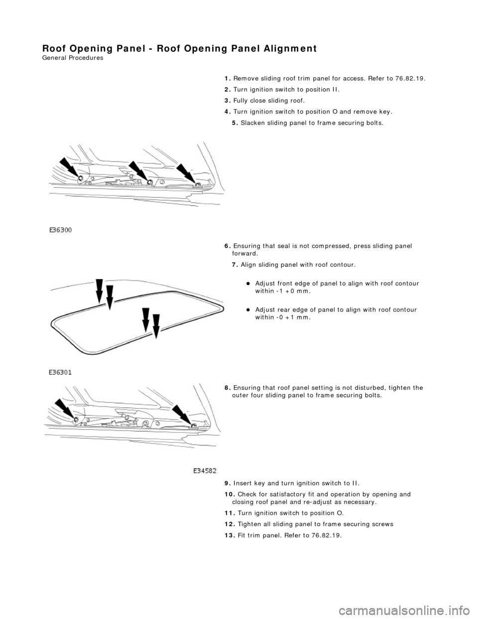
5. Slacken sliding panel to frame securing bolts.
6. Ensuring that seal is not compressed, press sliding panel
forward.
7. Align sliding panel with roof contour.
Adjust front edge of panel to align with roof contour
within -1 +0 mm.
Adjust rear edge of panel to align with roof contour
within -0 +1 mm.
8. Ensuring that roof panel settin g is not disturbed, tighten the
outer four sliding panel to frame securing bolts.
9. Insert key and turn ig nition switch to II.
10. Check for satisfactory fit and operation by opening and
closing roof panel and re -adjust as necessary.
11. Turn ignition switch to position O.
12. Tighten all sliding panel to frame securing screws
13. Fit trim panel. Refer to 76.82.19.
Page 2336 of 2490
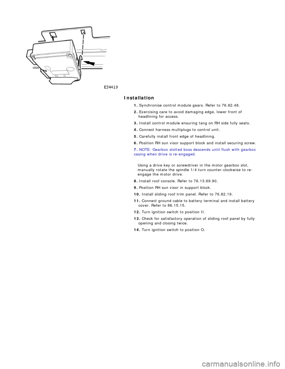
Installation
1. Synchronise control module gears. Refer to 76.82.48.
2. Exercising care to avoid da maging edge, lower front of
headlining for access.
3. Install control module ensuring tang on RH side fully seats.
4. Connect harness multiplugs to control unit.
5. Carefully install front edge of headlining.
6. Position RH sun visor support bl ock and install securing screw.
7. NOTE: Gearbox slotted boss descends until flush with gearbox
casing when drive is re-engaged.
Using a drive key or screwdriver in the motor gearbox slot,
manually rotate the spindle 1/4 turn counter-clockwise to re-
engage the motor drive.
8. Install roof console. Refer to 76.13.69.90.
9. Position RH sun visor in support block.
10. Install sliding roof trim panel. Refer to 76.82.19.
11. Connect ground cable to batter y terminal and install battery
cover. Refer to 86.15.15.
12. Turn ignition switch to position II.
13. Check for satisfactory operation of sliding roof panel by fully
opening and closing twice.
14. Turn ignition switch to position O.
Page 2339 of 2490
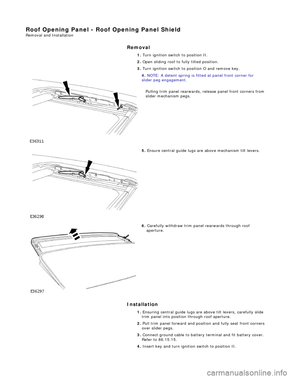
Roof Opening Panel - Roof Opening Panel Shield
Removal and Installation
Removal
Installation
1. Turn ignition switch to position II.
2. Open sliding roof to fully tilted position.
3. Turn ignition switch to po sition O and remove key.
4. NOTE: A detent spring is fitt ed at panel front corner for
slider peg engagement.
Pulling trim panel rearwards, release panel front corners from
slider mechanism pegs.
5. Ensure central guide lugs are above mechanism tilt levers.
6. Carefully withdraw trim panel rearwards through roof
aperture.
1. Ensuring central guide lugs are ab ove tilt levers, carefully slide
trim panel into position through roof aperture.
2. Pull trim panel forward and positi on and fully seat front corners
over slider pegs.
3. Connect ground cable to battery terminal and fit battery cover.
Refer to 86.15.15.
4. Insert key and turn ignition switch to position II.
Page 2340 of 2490

5.
Fully close sliding roof, checking that operation is satisfactory
and trim panel remain s correctly fitted.
6. Turn ignition switch to position O.
Page 2341 of 2490
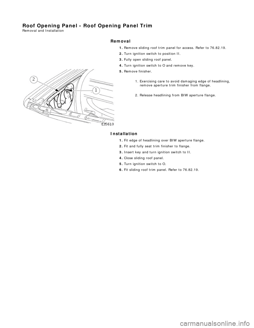
Roof Opening Panel - Roof Opening Panel Trim
Removal and Installation
Removal
Installation
1.
Remove sliding roof trim panel for access. Refer to 76.82.19.
2. Turn ignition switch to position II.
3. Fully open sliding roof panel.
4. Turn ignition switch to O and remove key.
5. Remove finisher.
1. Exercising care to avoid damaging edge of headlining,
remove aperture trim finisher from flange.
2. Release headlining from BIW aperture flange.
1. Fit edge of headlining over BIW aperture flange.
2. Fit and fully seat trim finisher to flange.
3. Insert key and turn ig nition switch to II.
4. Close sliding roof panel.
5. Turn ignition switch to O.
6. Fit sliding roof trim panel. Refer to 76.82.19.