Page 1393 of 2490

2.2. Switch OFF the ignition.
3. 3. Wait 10 seconds.
4. 4. Start the engine.
5. 5. Select R (reverse will be selected).
6. 6. Select D ( 2 will be selected).
The limp-home mode will be retained until the fault is remedied or the fault code has been erased. Intermittent faults may
be cleared by cycling the ignition OFF/ON. In certain cases the component may need to be operated before the fault code is
cleared eg. a shift solenoid.
Emergency Running (mechanica l/hydraulic limp-home mode)
Should slip be detected, due to a mechanical failure or loss of pressure, the transmission will either shift to, and hold 3 or
shift to, and hold, the last gear which was known to be alright. This condition may be cleared by cycling the ignition OFF/ON
following mechanical repair.
The operator will be made aware of certain faults by a warning message on th e instrument cluster.
Data concerning OBDII related transmission failures is stored in the ECM for access via the J1962 socket.
Safety Functions
These functions are designed to safeguard against inappropriate actions by the operator as well as system malfunctions.
The electrical and diagnostic system has been designed such that system integrity is protected at all times, the safety
concept being based on th e following three points.
1. 1. The hydraulic system has 'fail-safe' characteristics regardin g its electrical operation, such that should the power
supply be lost to the electro-hydraulic actuators the transmission will initiate a limp-home mode.
2. 2. Recognition of critical shift operation by monitoring the last element in the signal path, ie the solenoid valve, and
checking by means of redundant me asured variables relative to engine, transmission and road speeds.
3. 3. Each time the vehicle is started there is a check on the entire safety hardware and the associated program parts
and signal paths. A malfunction in this part of the system, or triggering of the safety circuit, is communicated to
the operator by a warning messag e on the instrument cluster.
CAUTION: Do not engage R or P with the vehicle in motion.
Should R be engaged with the vehicle in forward motion, the transmission will default to neutral until either the vehicle
speed decreases to 4 mph or D is selected.
Towing
The vehicle may be towed provided that:
Selector in position N Speed < 50 kph Distance < 50 km
System Functions
'J' Gate Layout
Page 1465 of 2490

The Drive-to-fourth switch:
Detects when the gear selector lever is moved from Drive to Fourth. Is hard-wired to the transmission control module.
The Neutral position switch:
Is hard-wired to the body processor module. Detects when the gear selector lever is moved to the Neutral position.
The Park position switch:
Is hard-wired to the body processor module. Detects when the gear selector leve r is moved to the Park position.
The gear selector module:
Provides illumination of the gear sele ctor surround, which is dimmable via a CA N signal from the instrument cluster. Provides red illumination, on the gear selector surround, of the gear selected, by CAN signals from the instrument
cluster.
Illuminates the security system Active LED on the gear se lector surround, in response to an input from the body
processor module.
Is connected to the fascia harness via a 12-way connector. Refer to Connec tor Pins Identification, 307-01A.
The gear selector interlock solenoid:
Prevents the gear selector lever from be ing moved from the Park position, unless th e ignition switch is in position II,
and the brake pedal is depressed.
Is controlled by an input from the body processor module.
The seven gear selector positions are:
P : The transmission is mechanically locked (starting available). R : Reverse gear. N : No power to the rear wh eels (starting available). D : All 5 forward gears available. 4 : Upshift to 4th gear only. 3 : Upshift to 3rd gear only. 2 : Upshift to 2nd gear only.
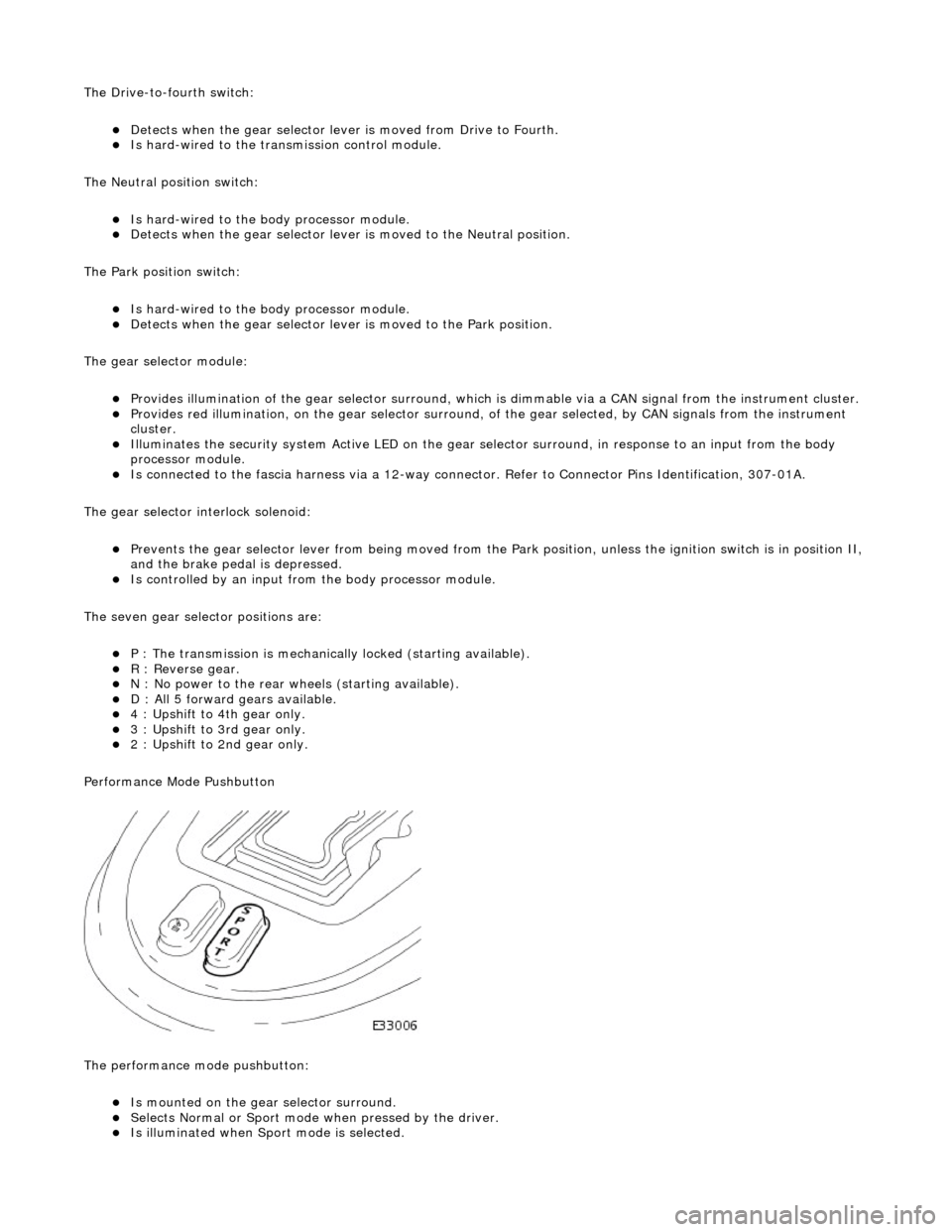
Performance Mode Pushbutton
The performance mode pushbutton:
Is mounted on the gear selector surround. Selects Normal or Sport mode when pressed by the driver. Is illuminated when Sport mode is selected.
Page 1501 of 2490

Selector lever:
Gear selector positions are:
P Transmission mechanically locked, starting available * R Reverse gear N Neutral gear, no power to the rear wheels (starting available) D Drive gear, all 5 forward gears available (see Performance Mode Pushbutton) 4 Upshift to 4th gear only 3 Upshift to 3rd gear only 2 Upshift to 2nd gear only
Gearshift Interlock Manual Override*
The interlock system which locks the sele ctor in P and prevents the ignition key from being removed except when P is
selected, may be manually overridden in the event of an emergency.
1. 1. With the parking brake applied
2. 2. Remove the access blank using a suitable Torx bit
3. 3. Insert a small screwdriver into the vacated hole
4. 4. Push the screwdriver downwards, gently, and hold whilst simultaneously moving the selector from P towards R ,
but do not engage R until the tool has been removed
5. 5. An audible warning may be heard when operation 4 is carried out
6. 6. With the selector in N and the access bl ank replaced, the vehicle may be started
Range Selection
The selector lever transmits operator demand to the transmission and TCM by means of a cable and Dual-Linear
Switch (DLS).
The lever operates the transmission assemb ly selector shaft, only for P R N D , by means of a cable. Movement of the
lever across the gate to 4, 3 and 2 positions disengages th e cable from the selector lever and engages the DLS which
controls gear selection electronically.
Gear selector module:
Provides illumination of the decal relevant to the gear sele cted. This information is provided by CAN from the TCM. Illuminates the security system Active LED on the gear selector surround, in response to an output from the BPM.
Transmission Switches
Performance Mode Pushbutton
7—Connector - Climate control
8—Solenoid - Gear selector
9—Security system Active LED
Page 1502 of 2490

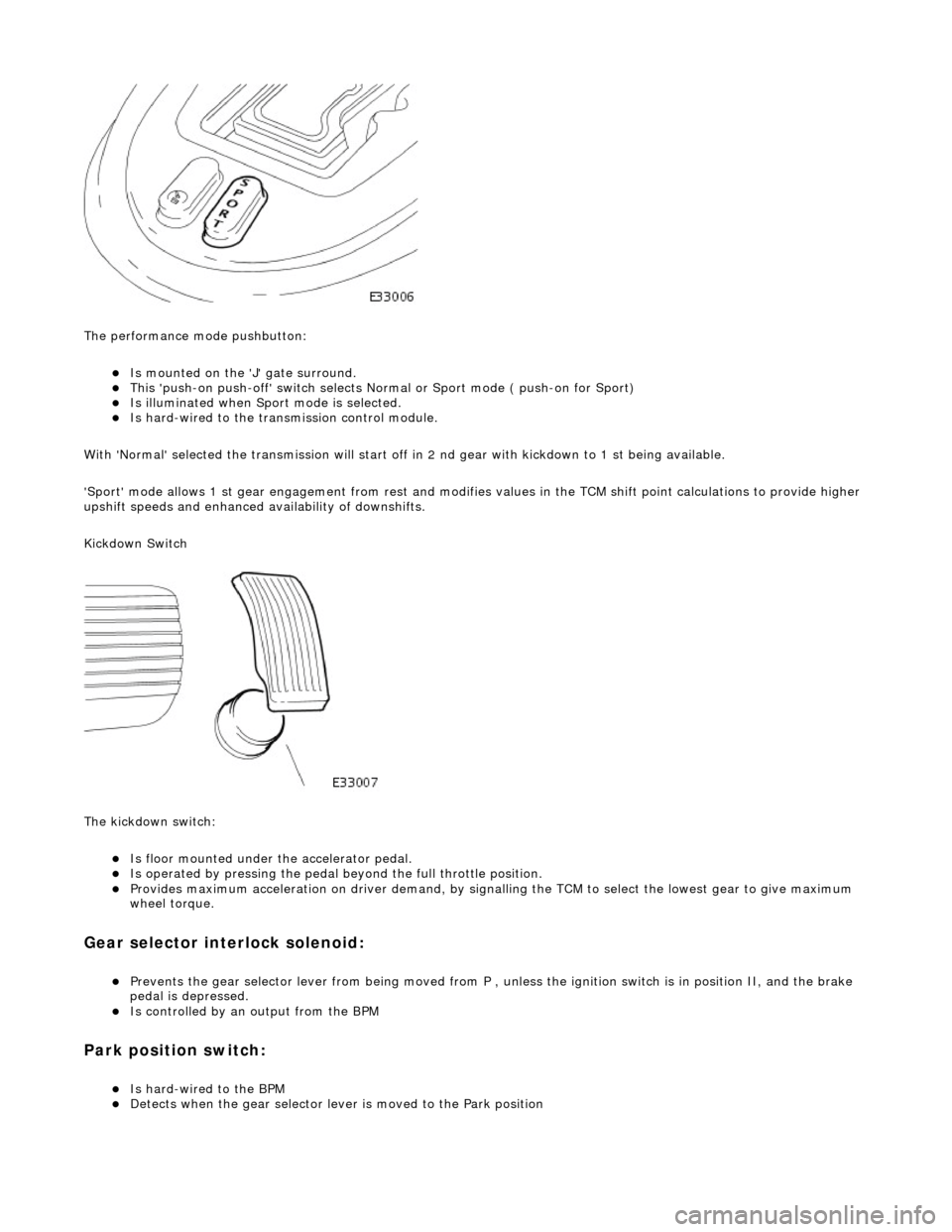
The performance mode pushbutton:
Is mounted on the 'J' gate surround. This 'push-on push-off' swit ch selects Normal or Sport mode ( push-on for Sport) Is illuminated when Sport mode is selected. Is hard-wired to the transmission control module.
With 'Normal' selected the transmissi on will start off in 2 nd gear with kickdown to 1 st being available.
'Sport' mode allows 1 st gear en gagement from rest and modifies values in the TCM shift point calculations to provide higher
upshift speeds and enhanced availability of downshifts.
Kickdown Switch
The kickdown switch:
Is floor mounted under th e accelerator pedal. Is operated by pressing the pedal beyond the full throttle position. Provides maximum acceleration on driver demand, by signalling the TCM to select the lowest gear to give maximum
wheel torque.
Gear selector interlock solenoid:
Prevents the gear selector lever from being moved from P , unless the ignition switch is in position II, and the brake
pedal is depressed.
Is controlled by an output from the BPM
Park position switch:
Is hard-wired to the BPM Detects when the gear selector lever is moved to the Park position
Page 1520 of 2490
moving the set position of either the gear selector lever or the selector lever on the transmission casing.
3. Tighten to 22-28 Nm.
4. Verify the 'N' setting.
6. Check that all released connec tors are safely insulated and
connect the vehicle battery.
7. Switch ON the ignition.
8. Adjust the position of the linear switch so that the selector 'N'
position graphic illuminates. Ti ghten the four screws to 0,7-1
Nm.
9. Move the gear selector to 'R' to confirm that the 'R' position
graphic illuminates.
10. Check that the engine will start when the gear selector is in
the 'N' and 'P' positions, bu t not in any other position.
11. Move the gear selector to 'N'.
12. Switch OFF the ignition.
13. Disconnect the battery.
14. Install the console assembly, operation 76.25.01.
15. Install the console finisher veneer panel, operation 76.47.26.
16. Install the J-gate surround, operation 76.25.24.
17. Perform the Battery Reconnection Procedure described in
Operation 86.15.15.
Page 1535 of 2490
Connect the scan tool 1
Have the DTC(s) and freeze frame data been recorded?
Yes GO to A2
A2: CHECK O2 SENSOR HEATER CONTINUITY
Ignition switch to position 0 1
Disconnect EM021
Bracket on top of gearbox or Bulkhead rear of engine
2
With EM021 disconnected, measure the resistance between
EM021/001 and EM021/002. 3
Is the resistance between 4 and 10 OHM?
Yes
GO to A3
No Renew O2 sensor; reconnect plug(s)
GO to A6
A3: CHECK FOR O2 SENSOR FAILURE
Run the engine for a period to warm the sensor and then
maintain a steady speed of approximately 2500 rpm. 1
Disconnect EM021 2
Page 1542 of 2490
Ignition switch to position 0 1
Disconnect EM010 and EM012
Inside ECM housing
2
Ignition switch to position II 3
Measure the voltage between EM010/023 and EM012/015 4
Is the voltage 0 (zero) V?
Yes GO to A15
No Inspect harness / connectors EM010, EM012, and EM021 for
corrosion, damaged / pushed back pins. Repair as required
and reconnect plug(s).
GO to A18
A15: CHECK FOR SHORT TO B+
Measure the voltage between EM010/023 and EM012/022 1
Page 1544 of 2490
Ignition switch to position 0 1
Remove EMS fuse F14 2
Disconnect EM010 and EM015
Inside ECM housing
3
Using a link lead, bridge EM010/016 and EM010/022 4
Ignition switch to position II 5
Measure the voltage between EM010/023 and EM015/002 6
Is the voltage 0 (zero) V?
Yes Replace EMS fuse F14 but retain link lead
GO to A17
No Inspect harness / connectors EM010, EM015, and EM021 for
corrosion, damaged / pushed back pins. Repair as necessary
and reconnect plug(s).
GO to A18
A17: CHECK B+ AT O2 SENSOR HEATER CIRCUIT