1998 JAGUAR X308 ignition switch
[x] Cancel search: ignition switchPage 962 of 2490

All vehicles
21.
N
OTE: Install a new sealing washer.
• NOTE: Clean off any spillages.
Install the supercharger coolant fill plug.
Tighte
n to 45 Nm.
22. Remove the coolant expans ion tank pressure cap.
23. Switch ignition on.
24. CAUTION: Do not allow the supercharger water pump to
run dry. Failure to follow this instruction may result in damage to
the vehicle.
• NOTE: Leave the ignition switched on (do not start the engine)
for at least 2 minutes to allow the air charge cooler electric water
pump to operate and to purge an y air from the air charge cooler
radiator to the header tank.
Allow the supercharger pump to run and top up the system
through the coolant expansion tank.
25 . Swit
ch the ignition off.
26. Install the coolant expansion tank pressure cap.
27. START and RUN the engine.
28. CAUTION: Observe the engine temperature gauge. If
the engine starts to over-heat switch off immediately and allow to
cool. Failure to follow this inst ruction may cause damage to the
vehicle.
Run the engine at between 1500 and 2000 rpm until the cooling
fan operates.
29 .
Swi
tch off the engine.
30. Allow the engine to cool.
31. Check and top-up the coolant if required.
Page 1012 of 2490
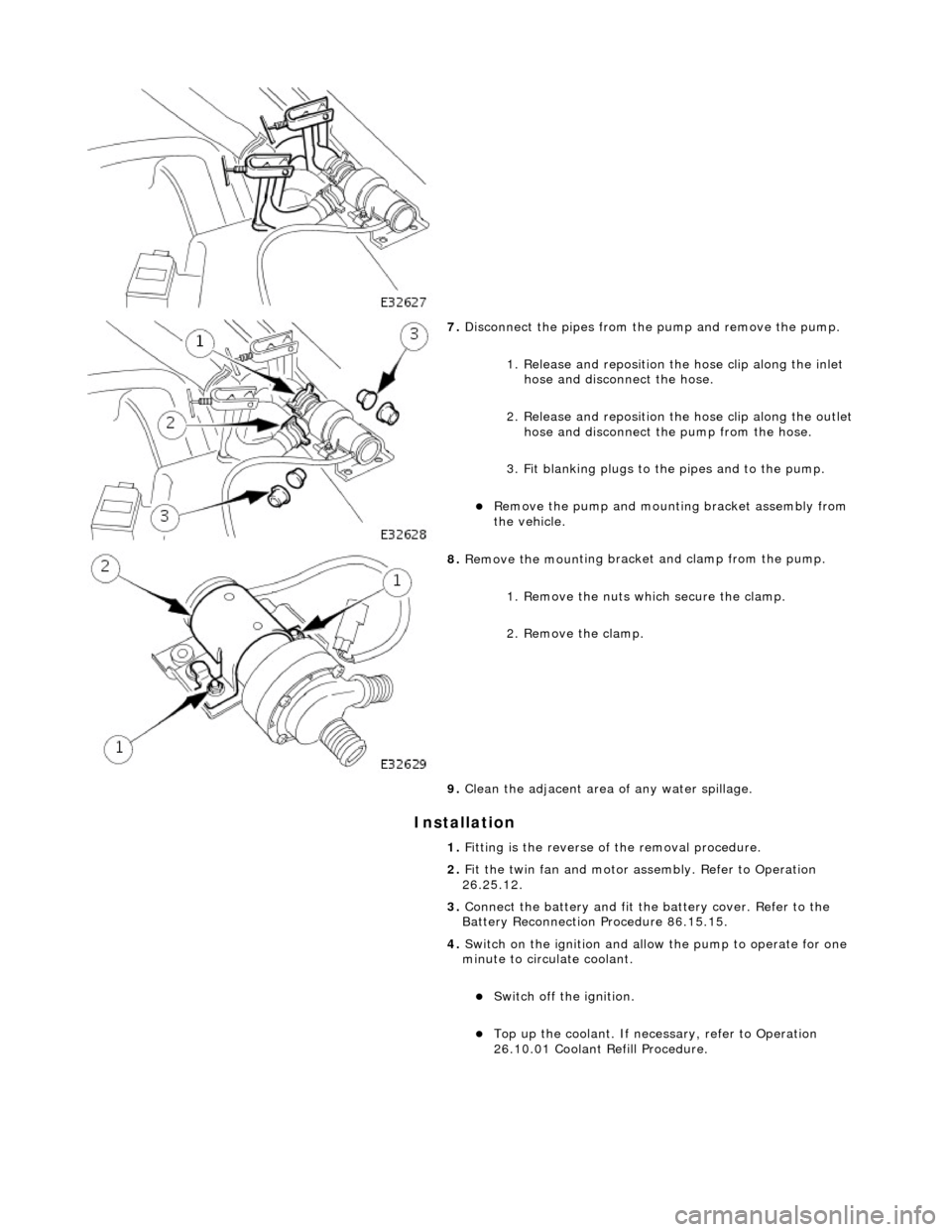
In
stallation
7.
Disc
onnect the pipes from the
pump and remove the pump.
1. Release and reposition th e hose clip along the inlet
hose and discon nect the hose.
2. Release and reposition the hose clip along the outlet
hose and disconnect th e pump from the hose.
3. Fit blanking plugs to the pipes and to the pump.
Remove t
he pump and mounting bracket assembly from
the vehicle.
8. Remove the moun
ting bracket and clamp from the pump.
1. Remove the nuts which secure the clamp.
2. Remove the clamp.
9. Clean the adjacent area of any water spillage.
1. Fitting is the reverse of the removal procedure.
2. Fit the twin fan and motor assembly. Refer to Operation
26.25.12.
3. Connect the battery and fit the battery cover. Refer to the
Battery Reconnection Procedure 86.15.15.
4. Switch on the ignition and allow the pump to operate for one
minute to circulate coolant.
Swit ch
off the ignition.
Top up th
e coolant
. If ne
cessary, refer to Operation
26.10.01 Coolant Refill Procedure.
Page 1020 of 2490
Fuel Char
ging and Controls - Fuel Charging and Controls
D
iagn
osis and Testing
I
n
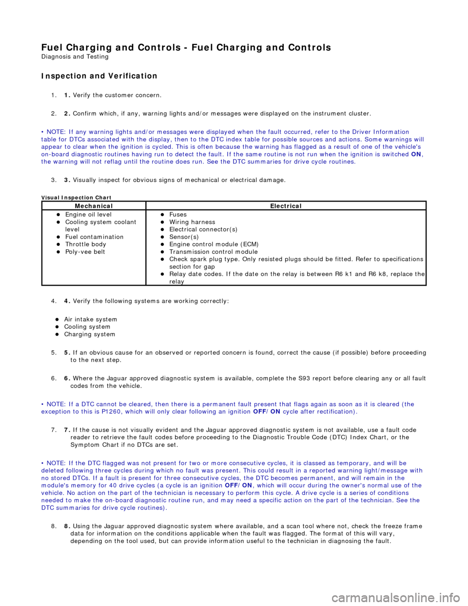
spection and Verification
1.
1. Veri fy the customer concern.
2. 2. Confi
rm which, if any, warning li
ghts and/or messages were displayed on the instrument cluster.
• NOTE: If any warning lights and/or me ssages were displayed when the fault occurred, refer to the Driver Information
table for DTCs associated with the display, then to the DTC index table for possible sources and actions. Some warnings will
appear to clear when the ignition is cycl ed. This is often because the warning has flagged as a resu lt of one of the vehicle's
on-board diagnostic routines having run to detect the fault. If the same routine is not run when the ignition is switched ON,
the warning will not reflag until the routine does run. See the DTC summaries for drive cycle routines.
3. 3. Visually inspect for obvious signs of mechanical or electrical damage.
Vi
sual Inspection Chart
4.
4. Veri fy the foll
owing syst
ems are working correctly:
Air intake
system
Cooling system
Charging system
5. 5. If
an obvious cause for an observed or
reported concern is found, correct th e cause (if possible) before proceeding
to the next step.
6. 6. Where the Jaguar approved diagnostic sy stem is available, complete the S93 report before clearing any or all fault
codes from the vehicle.
• NOTE: If a DTC cannot be cleared, then there is a permanent fault present that flag s again as soon as it is cleared (the
exception to this is P1260, which will only clear following an ignition OFF/ON cycle after rectification).
7. 7. If the cause is not visually evident and the Jaguar approv ed diagnostic system is not available, use a fault code
reader to retrieve the fault codes be fore proceeding to the Diagnostic Trou ble Code (DTC) Index Chart, or the
Symptom Chart if no DTCs are set.
• NOTE: If the DTC flagged was not present for two or more co nsecutive cycles, it is classed as temporary, and will be
deleted following three cycl es during which no fault was present. This could result in a reported wa rning light/message with
no stored DTCs. If a fault is present for three consecutive cycles, the DTC becomes permanent, and will remain in the
module's memory for 40 drive cycl es (a cycle is an ignition OFF/ON, which will occur during the owner's normal use of the
vehicle. No action on the part of the technician is necessary to perform this cycle. A drive cycle is a series of conditions
needed to make the on-board diagnostic ro utine run, and may need a specific action on the part of the technician. See the
DTC summaries for drive cycle routines).
8. 8. Using the Jaguar approved diagnostic system where available, and a scan tool where not, check the freeze frame
data for information on the conditions applicable when the fault was flagged. The format of this will vary,
depending on the tool used, but can pr ovide information useful to the technician in diagnosing the fault.
MechanicalElectrical
Engine
oil level
Coo
ling system coolant
lev
el
Fuel contamination
Throttle body Poly-ve
e belt
Fu
ses
W
i
ring harness
E
l
ectrical connector(s)
Sens
o
r(s)
Engine
control module (E
CM)
Tran
s
mission control module
Check spark plu
g type. Only r
e
sisted plugs should be fitted. Refer to specifications
section for gap
Relay date codes. I
f the date on the rela
y is between R6 k1 and R6 k8, replace the
relay
Page 1022 of 2490
(ECT) se
nsor
Blocked part-load breather
(s
ervice action S474)
Injec
t
or leak
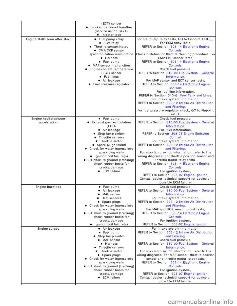
Engine stalls
soon
after start
F
u
el pump relay
ECM relay Thr
o
ttle contaminated
CMP/CKP sen
s
or
synchronization malfunction
Harness Fuel
pump
MAF
s
ensor malfunction
Engine coolan
t
temperature
(ECT) sensor
Fue l
lines
Air leakage Fu
el pressure regulator
F
o
r fuel pump relay tests,
GO to Pinpoint Test E.
.
F or ECM
relay tests,
REFER to Section 303
-14 Elec tronic En
gine
Controls.
Check bull etins for throttl
e cleaning procedure. For
CMP/CKP sensor tests,
REFER to Section 303
-14 Elec tronic En
gine
Controls.
Chec k fu
el pressure,
REFER to Section 310
-00 Fu
el System
- Ge
n
eral
Informati
o
n
.
F or MAF sensor and
ECT sensor tests,
REFER to Section 303
-14 Electronic En
gine
Controls.
For fuel l
ine information,
REFER to Section 310
-01
Fuel Tank and Lines
.
F or i
ntake system information,
REFER to Section 303
-1 2
Intake Air Distribution
and F
ilt
ering
.
F o
r fuel pressure regulato
r check, GO to Pinpoint
Test D.
.
Engine h e
sitates/poor
acceleration
Fue l
pump
Exhaus
t gas
recirculation
(EGR)
Air leakage Stop lamp swi t
ch
Throttl
e
sensors
Throttl
e
motor
Spark plugs
fouled
Check f
o
r water ingress into
spark plug wells
Ignition coil fail
ure(s)
HT sho
rt to ground (tracking)
check rubber
boots for
cracks/damage
ECM failu r
e
Chec
k fu
el pressure,
REFER to Section 310
-00 Fu
el System
- Ge
n
eral
Informati
o
n
.
F o
r EGR information,
REFER to Section 303
-08 En gin
e Emission
Control.
F or i
ntake system information,
REFER to Section 303
-1 2
Intake Air Distribution
and F
ilt
ering
.
F or stop l
amp switch in
formation, refer to the
wiring diagrams. For throttle position sensor and throttle motor relay tests,
REFER to Section 303
-14 Elec tronic En
gine
Controls.
For ign i
tion system,
REFER to Section 303
-07 En
gine Ignition
.
Contact dealer techn i
cal
support for advice on
possible ECM failure.
Engine ba ckfiresFuel
pump
Air leakage MAF s
e
nsor
HO2 sensors Spark plugs
Check fo
r water ingress into
spark plug wells
HT short to ground (tracking) check rubber
boots for
cracks/damage
Ignition coil fail
ure(s)
Chec
k fu
el pressure,
REFER to Section 310
-00 Fu
el System
- Ge
n
eral
Informati
o
n
.
F or i
ntake system information,
REFER to Section 303
-1 2
Intake Air Distribution
and F
ilt
ering
.
For MAF and HO2
sensor circuit tests,
REFER to Section 303
-14 Electronic En
gine
Controls.
For igni
tion system,
REFER to Section 303
-07 En
gine Ignition
.
Engine
s
urges
Air leakage Fue
l
pump
Stop lamp swi
t
ch
MAF s
e
nsor
Harness Throttl
e
sensors
Throttl
e
motor
Spark plugs
Check fo
r water ingress into
spark plug wells
HT sho rt to ground (tracking)
check rubber
boots for
cracks/damage
ECM failu r
e
F
or i
ntake system information,
REFER to Section 303
-1 2
Intake Air Distribution
and F
ilt
ering
.
Chec k fu
el pressure,
REFER to Section 310
-00 Fu
el System
- Gen
e
ral
Informati
o
n
.
F or stop l
amp switch in
formation, refer to the
wiring diagrams. For MAF se nsor, throttle position
sensor and throttle motor relay tests,
REFER to Section 303
-14 Elec tronic En
gine
Controls.
For ign i
tion system,
REFER to Section 303
-07 En
gine Ignition
.
Contact dealer techn i
cal
support for advice on
possible ECM failure.
Page 1031 of 2490
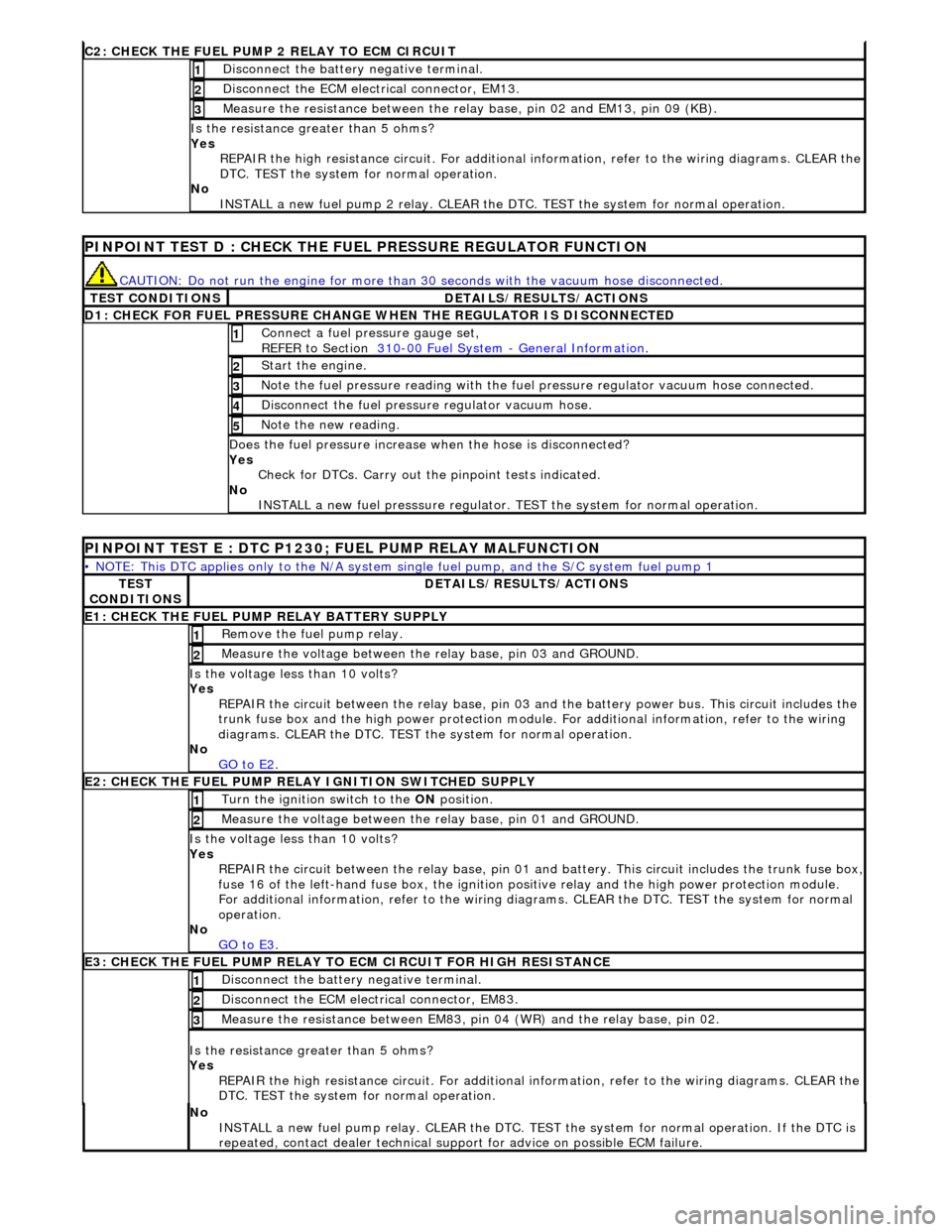
C2: CHECK THE FUEL
PUMP 2 RELAY TO ECM CIRCUIT
Di
sconnect the battery negative terminal.
1
D
isconnect the ECM electrical connector, EM13.
2
Meas
ure the resistance between the rela
y base, pin 02 and EM13, pin 09 (KB).
3
Is th
e resistance greater than 5 ohms?
Yes REPAIR the high resistance circuit. For additional information, refer to the wiring diagrams. CLEAR the
DTC. TEST the system for normal operation.
No INSTALL a new fuel pump 2 relay. CLEAR the DT C. TEST the system for normal operation.
P
INPOINT TEST D : CHECK THE FUEL PRESSURE REGULATOR FUNCTION
CAUTI
ON: Do not run the engine for more than
30 seconds with the vacuum hose disconnected.
T
EST CONDITIONS
D
ETAILS/RESULTS/ACTIONS
D
1: CHECK FOR FUEL PRESSURE CHANGE
WHEN THE REGULATOR IS DISCONNECTED
Connect a
fuel pressure gauge set,
REFER to Section 310
-00
Fuel System
-
General Informati
on
. 1
St
art the engine.
2
N
ote the fuel pressure readin
g with the fuel pressure regu lator vacuum hose connected.
3
Di
sconnect the fuel pressu
re regulator vacuum hose.
4
N
ote the new reading.
5
Doe
s the fuel pressure increase when the hose is disconnected?
Yes Check for DTCs. Carry out the pinpoint tests indicated.
No INSTALL a new fuel presssure regulator. TEST the system for normal operation.
P
INPOINT TEST E : DTC P1230;
FUEL PUMP RELAY MALFUNCTION
•
NOTE: This DTC applies only to the N/A system si
ngle fuel pump, and the S/C system fuel pump 1
TE
ST
CONDITIONS
D
ETAILS/RESULTS/ACTIONS
E1
: CHECK THE FUEL PUMP
RELAY BATTERY SUPPLY
R
emove the fuel pump relay.
1
Meas
ure the voltage between the
relay base, pin 03 and GROUND.
2
Is th
e voltage less than 10 volts?
Yes REPAIR the circuit between the rela y base, pin 03 and the battery power bus. This circuit includes the
trunk fuse box and the high power protection module . For additional information, refer to the wiring
diagrams. CLEAR the DTC. TEST th e system for normal operation.
No GO to E2
.
E2
: CHECK THE FUEL PUMP RELAY IGNITION SWITCHED SUPPLY
Turn the ignition swi
tch to the
ON position.
1
Meas
ure the voltage between the
relay base, pin 01 and GROUND.
2
Is th
e voltage less than 10 volts?
Yes REPAIR the circuit between the rela y base, pin 01 and battery. This circuit includes the trunk fuse box,
fuse 16 of the left-hand fuse box, the ignition po
sitive relay and the high power protection module.
For additional information, refer to the wiring diagrams. CLEAR the DTC. TEST the system for normal
operation.
No GO to E3
.
E3
: CHECK THE FUEL PUMP RELAY TO
ECM CIRCUIT FOR HIGH RESISTANCE
Di
sconnect the battery negative terminal.
1
D
isconnect the ECM electrical connector, EM83.
2
Meas
ure the resistance between EM83, pi
n 04 (WR) and the relay base, pin 02.
3
Is th
e resistance greater than 5 ohms?
Yes REPAIR the high resistance circuit. For additional information, refer to the wiring diagrams. CLEAR the
DTC. TEST the system for normal operation.
No
INSTALL a new fuel pump relay. CLEAR the DTC. TEST the system for normal operation. If the DTC is
repeated, contact dealer technical support for advice on possible ECM failure.
Page 1064 of 2490
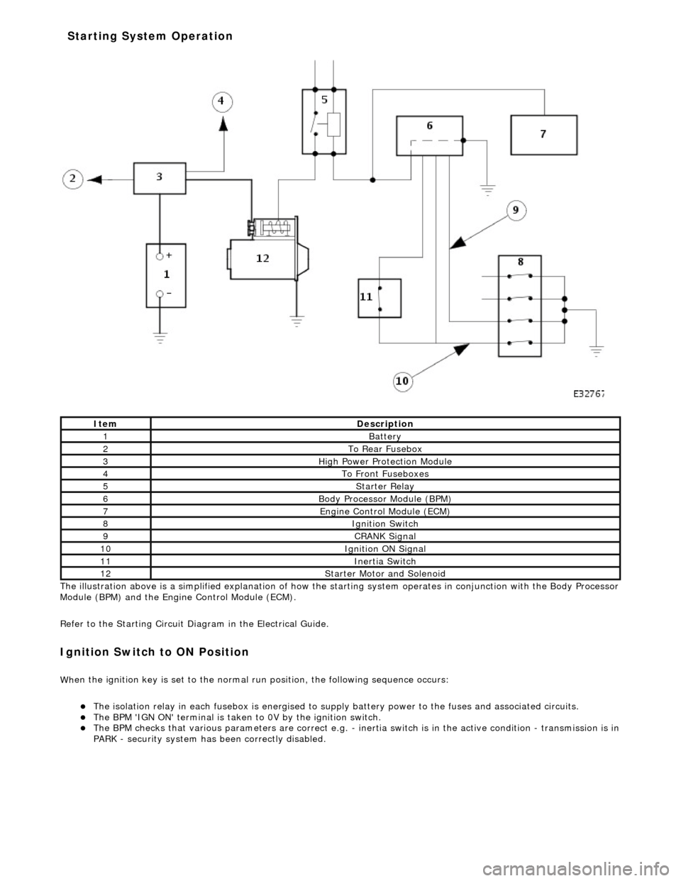
The il
lustration above is a simplified expl
anation of how the starting system operates in conjunction with the Body Processor
Module (BPM) and the Engine Control Module (ECM).
Refer to the Starting Circuit Diagram in the Electrical Guide.
I g
nition Switch to ON Position
W
h
en the ignition key is set to the normal run position, the following sequence occurs:
The
is
olation relay in each fusebox is
energised to supply battery power to the fuses and associated circuits.
The BPM 'IGN
ON' terminal
is taken to 0V by the ignition switch.
The BPM
checks that various parameters are correct e.g. -
inertia switch is in the active condition - transmission is in
PARK - security system has been correctly disabled.
It e
m
De
scr
iption
1Batt
ery
2To Re ar
Fusebox
3Hi
gh Power Pr
otection Module
4To Front
Fu
seboxes
5Starter Re
lay
6Body Processor M
odule (BPM)
7Engine
C
ontrol Module (ECM)
8Ignition Switch
9CRANK Signal
10Ignition ON Signal
11Inertia Switch
12St
arte
r Motor and Solenoid
Starting System Operation
Page 1065 of 2490
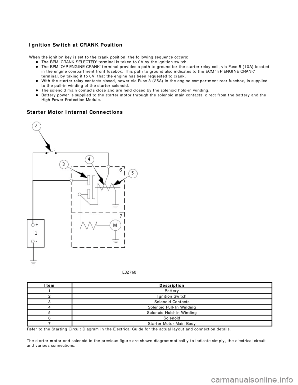
The BPM
'CRANK SELECTED' terminal is ta
ken to 0V by the ignition switch.
The BPM
'O/P ENGINE CRANK' terminal pr
ovides a path to ground for the starte r relay coil, via Fuse 5 (10A) located
in the engine compartment front fusebo x. This path to ground also indicates to the ECM 'I/P ENGINE CRANK'
terminal, by taking it to 0V, that the engine has been requested to crank.
Wi
th the starter relay contacts closed,
power via Fuse 3 (25A) in the engine compartment rear fusebox, is supplied
to the pull-in winding of the starter solenoid.
The s
olenoid main contacts close and are held
closed by the solenoid hold-in winding.
Battery power is supplied
to
the starter motor through the solenoid main contacts, direct from the battery and the
High Power Protection Module.
Starter
Motor Internal Connections
Re
fer to the Starting Circuit Diagram in the Electrical
Guide for the actual layout and connection details.
The starter motor and solenoid in the previous figure are shown diagrammaticall y to indicate simply, the electrical circuit
and various connections.
It
em
De
scription
1Batt
ery
2Ignition Switch
3So
lenoid Contacts
4So
lenoid Pull-In Winding
5So
lenoid Hold-In Winding
6So
lenoid
7St
arter Motor Main Body
I
gnition Switch at CRANK Position
W
hen the ignition key is set to the crank position, the following sequence occurs:
Page 1069 of 2490
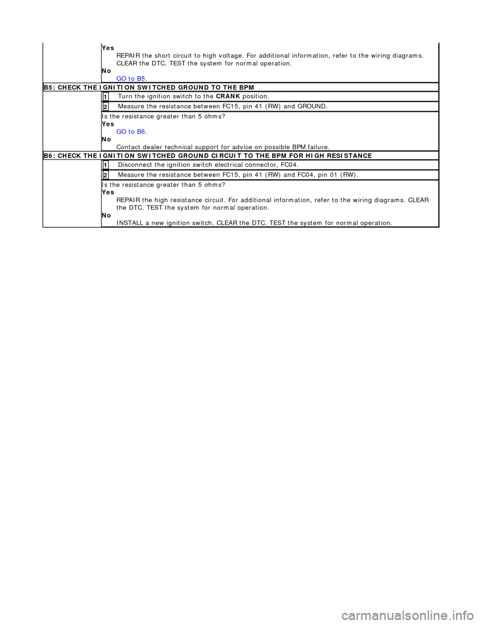
Yes
REPAIR the short circuit to high voltage. For addi tional information, refer to the wiring diagrams.
CLEAR the DTC. TEST the syst em for normal operation.
No GO to B5
.
B5: CHECK
THE IGNITION SWITCHED GROUND TO THE BPM
Turn the ignition swi
tch to the CRANK
position.
1
Meas
ure the resistance between FC15, pin 41 (RW) and GROUND.
2
Is th
e resistance greater than 5 ohms?
Yes GO to B6
.
No
Contact dealer technical support fo r advice on possible BPM failure.
B6: CHECK
THE IGNITION SWIT
CHED GROUND CIRCUIT TO THE BPM FOR HIGH RESISTANCE
Di
sconnect the ignition switch electrical connector, FC04.
1
Meas
ure the resistance between FC15,
pin 41 (RW) and FC04, pin 01 (RW).
2
Is th
e resistance greater than 5 ohms?
Yes REPAIR the high resistance circui t. For additional information, refer to the wiring diagrams. CLEAR
the DTC. TEST the system for normal operation.
No INSTALL a new ignition switch. CLEAR the DTC. TEST the system for normal operation.