Page 503 of 2490

Steering
Linkage - Steering Linkage
Descriptio
n and Operation
Parts List
The left- and right-hand tie rod assemblies:
T
ransmit steering forces from the steering rack to the st
eering arms which are integral with the vertical links.
Comprise the tie rod, inner
ball joint,
outer tie rod end and outer ball joint.
P
rovide front road wheel toe setting by adju
stment of the threaded outer tie rod ends.
• NOTE: Steering geometry adjustments must only be carried out wi th the vehicle on turn plates to allow the wheels to move
during adjustment.
The left- and right-hand steering rack gaiters:
Are
installed between the steering rack and the tie bars.
Are
of the concertina type.
R
etain lubricant and prevent th
e ingress of foreign matter.
P
ermit movement of the steering rack and tie rods.
ItemPa
rt Number
Descript
ion
1—St
eering rack assembly
2—St
eering rack gaiter
3—I
nner ball joint
4—Tie
rod
5—O
uter tie rod end
6—Lo
ck-nut
7—Oute
r ball joint
8—O
uter ball joint nut
Page 510 of 2490
The lower steeri ng col
umn:
Is a han
ded assembly
.
Incorporates
a col
umn to toeboard seal
which comprises a rolling element having two, low friction, PTFE rings. The
rolling element locates in a rubber b oot which seals to the toeboard.
Has a lowe
r universal joint connecting the
lower column to the steering rack.
Has an upper un
iversal joint connecting
the lower column to the upper column.
Has a NVH damper in
corporated into
the upper universal joint assembly.
May be installed in an
y orientation on the universal joint splines.
R
e
quires no setting or adjustment.
Has no s
e
rviceable components.
It is essential to disconnect the lower column from the steer ing rack before removing the engine or front suspension
crossbeam.
It e
m
Par
t
Number
De
scr
iption
1-Boot
2-Uni
v
ersal joint to upper column
3-Lower steeri
ng col
umn shaft
4-R
e
taining bolts
5-Uni
v
ersal joint to steering rack
Lower Steering Column
Page 511 of 2490
Steering Column - Steering Colu
mn Lower Shaft
Re
moval and Installation
Remov
al
1.
Raise
and support the vehicle.
For additional informat ion, refer to Section 100
-0
2 Jacking and
Liftin
g
.
2. De
tach the steering
column lower shaft.
1. Loosen the steering column lower shaft sliding joint retaining bolt.
2. Remove and discard the st eering column lower shaft
retaining bolt.
3. Detach the steering column lower shaft.
3. Lower the vehicle.
4. Remove an
d discard the steering
column lower shaft retaining
bolt.
5. De
tach the steering
column lower shaft.
6. Remove the steering column lower shaft.
De
tach the boot.
Page 530 of 2490

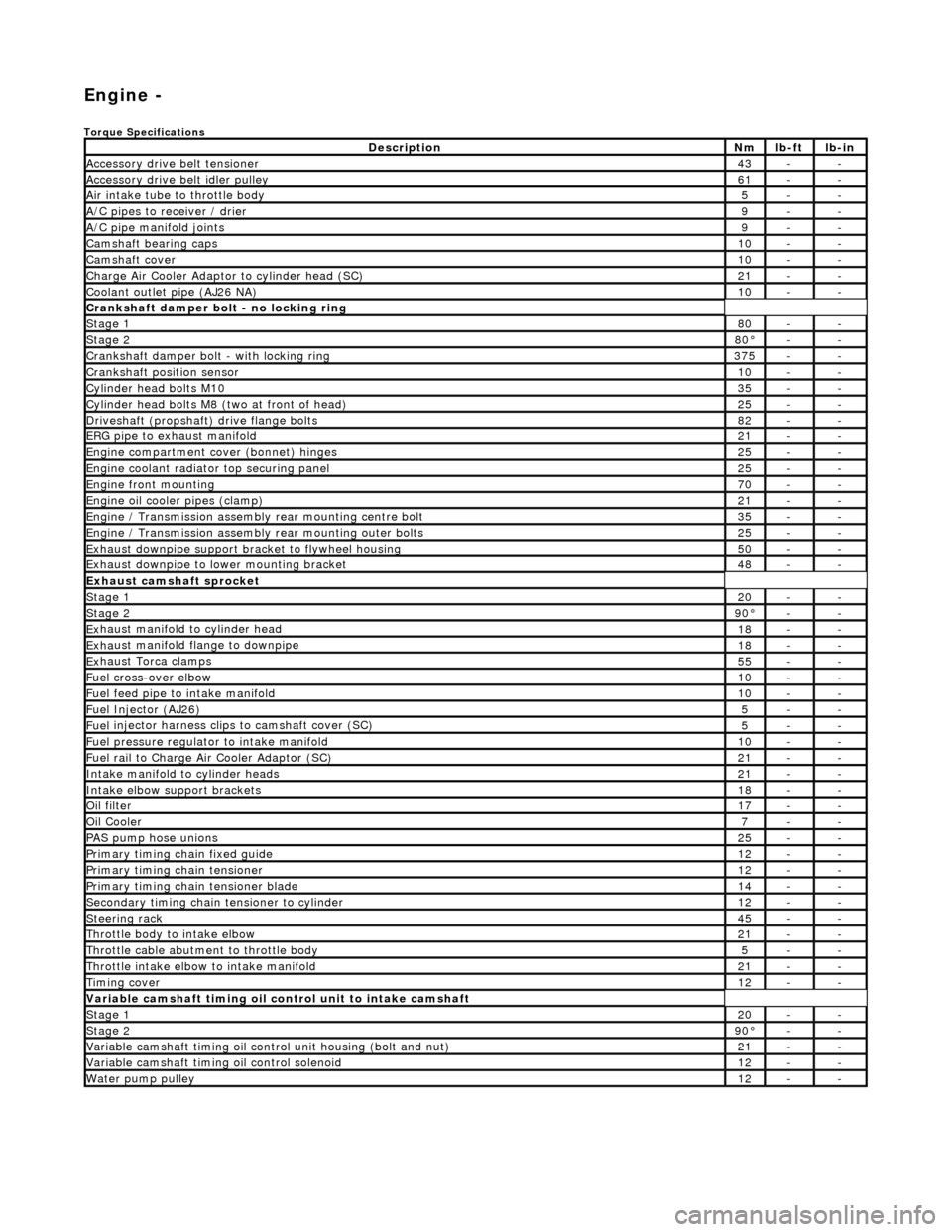
Engi
ne -
Torqu
e Specifications
De
s
cription
Nmlb
-
ft
lb
-
in
A
ccessory
drive belt tensioner
43--
A
ccessory
drive belt idler pulley
61--
Air in
ta
ke tube to throttle body
5--
A/C
pipes t
o receiver / drier
9--
A/C pipe m
anifold joints
9--
Camsh
aft bearin
g caps10--
Ca
msh
aft cove
r10--
Ch
arge Air Co
oler Adaptor to cylinder head (SC)
21--
Co
olan
t outlet pipe (AJ26 NA)
10--
Cran
kshaft damper bolt - no lockin
g ring
St
ag
e 1
80--
Stag
e 2
80°--
C
r
ankshaft damper bolt - with locking ring
37
5--
Cra
nkshaft position sensor
10--
Cy
li
nder head bolts M10
35--
Cy
lin
der head bolts M8 (two at front of head)
25--
Driv
es
haft (propshaft) drive flan
ge bo
l
ts
82--
ERG p
i
pe to exhaust manifold
21--
Engi
ne compartment cover (bonnet) hinges
25--
En
gine
coolant radiator top securing panel
25--
E
ng
ine front mounting
70--
En
gine
oil cooler pipes (clamp)
21--
En
gi
ne / Transmission assembly rear mounting centre bolt
35--
En
gi
ne / Transmission assembly rear mounting outer bolts
25--
Ex
ha
ust downpipe support bracket to flywheel housing
50--
Ex
ha
ust downpipe to lower mounting bracket
48--
E
x
haust camshaft sprocket
St
age 120--
Stage 290 °--
Ex
haust manifold to cylinder head
18--
Ex
ha
ust manifold flange to downpipe
18--
E
x
haust Torca clamps
55--
Fuel cross-over elbo
w
10--
Fu
el f
eed pipe to intake manifold
10--
Fuel
Injector (AJ
26)
5--
Fuel
injector ha
rness clips to camshaft cover (SC)
5--
Fu
el p
ressure re
gu
l
ator to intake manifold
10--
F
u
el rail to Char
ge
A
ir Cooler Adaptor (SC)
21--
In
ta
ke manifold to cylinder heads
21--
Inta
ke elbow support brackets
18--
Oil f
i
lter
17--
Oil C
o
oler
7--
P
AS pu
mp hose unions
25--
P
r
imary timing chain fixed guide
12--
P
r
imary timing chain tensioner
12--
Pr
imary timing chain tensioner blade
14--
S
e
condary timing chain tensioner to cylinder
12--
S
t
eerin
g ra
ck45--
Thro
ttle body to intake elbow
21--
Th
ro
ttle cable abutment to throttle body
5--
Th
ro
ttle intake elbow to intake manifold
21--
Ti
mi
ng cover
12--
Variable camshaft t
i
ming oil control unit to intake camshaft
St
ag
e 1
20--
St
ag
e 2
90
°--
Var
iable camshaft timing oil control unit housing (bolt and nut)
21--
Va
ria
ble camshaft timi
ng oil control solenoid
12--
Wa
ter pump pulley
12--
Page 566 of 2490
2.
Release the carrier from
the two ring dowels and
remove it.
6. Re
move the seals from the bush carrier.
1. Remove the sealing ring (scarf jointed) from the
carrier bush groove.
2. Remove the O-ring from the carrier oil-way recess.
7. Re
move the VVT bush carrier from the B-Bank.
1. Remove the two bolts and one nut which secure the carrier to the cylinder block.
2. Release the carrier from the two ring dowels and
remove it.
8. Re
move the seals from the bush carrier.
1. Remove the sealing ring (scarf jointed) from the
carrier bush groove.
2. Remove the O-ring from the carrier oil-way recess.
9. Raise the vehicle on a ramp.
10. Remove the crankshaft position sensor.
1. Remove the bolt which secures the crankshaft position sensor to the flywheel housing.
1. Re move
the sensor and allow it to hang free under
the engine.
Page 574 of 2490

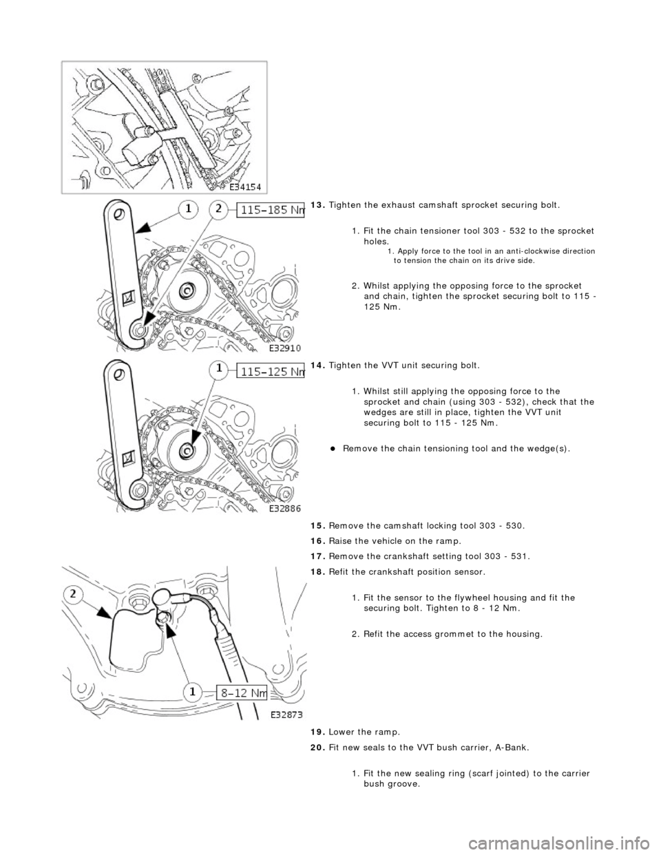
13. Tigh
ten the exhaust camshaft
sprocket securing bolt.
1. Fit the chain tensioner tool 303 - 532 to the sprocket holes.
1. Apply force to the to
ol in
an anti-clockwise direction
to tension the chain on its drive side.
2 .
Whilst applying the opposing force to the sprocket
and chain, tighten the sprock et securing bolt to 115 -
125 Nm.
14 . Tigh
ten the VVT unit securing bolt.
1. Whilst still applying the opposing force to the
sprocket and chain (using 303 - 532), check that the
wedges are still in place, tighten the VVT unit
securing bolt to 115 - 125 Nm.
R e
move the chain tensioning
tool and the wedge(s).
15. Remove the camshaft locking tool 303 - 530.
16. Raise the vehicle on the ramp.
17. Remove the crankshaft setting tool 303 - 531.
18 . R
efit the crankshaft position sensor.
1. Fit the sensor to the fl ywheel housing and fit the
securing bolt. Tighten to 8 - 12 Nm.
2. Refit the access grommet to the housing.
19. Lower the ramp.
20. Fit new seals to the VVT bush carrier, A-Bank.
1. Fit the new sealing ring ( scarf jointed) to the carrier
bush groove.
Page 575 of 2490

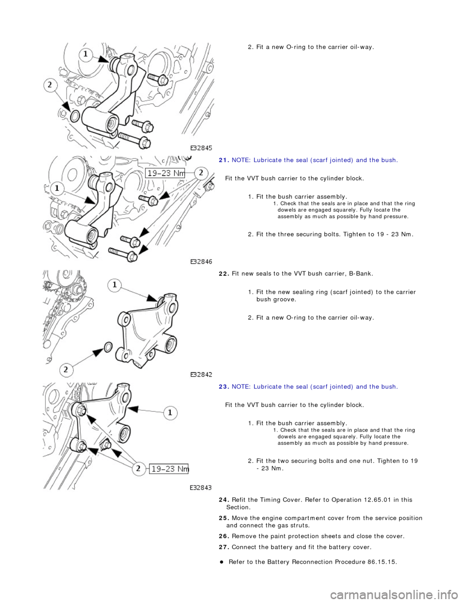
2
. Fit a new O-ring to the carrier oil-way.
21
.
NOTE: Lubricate the seal (s carf jointed) and the bush.
Fit the VVT bush carrier to the cylinder block.
1. Fit the bush carrier assembly.
1. C
heck that the seals are in place and that the ring
dowels are engaged squa rely. Fully locate the
assembly as much as possible by hand pressure.
2
. Fit the three securing bolts. Tighten to 19 - 23 Nm.
22
.
Fit new seals to the VVT bush carrier, B-Bank.
1. Fit the new sealing ring (scarf jointed) to the carrier bush groove.
2. Fit a new O-ring to the carrier oil-way.
23
.
NOTE: Lubricate the seal (s carf jointed) and the bush.
Fit the VVT bush carrier to the cylinder block. 1. Fit the bush carrier assembly.
1. C
heck that the seals are in place and that the ring
dowels are engaged squa rely. Fully locate the
assembly as much as possible by hand pressure.
2
. Fit the two securing bolts and one nut. Tighten to 19
- 23 Nm.
24. Refit the Timing Cover. Refer to Operation 12.65.01 in this
Section.
25. Move the engine compartment cover from the service position
and connect the gas struts.
26. Remove the paint protection sheets and close the cover.
27. Connect the battery and fit the battery cover.
Re
fer to the Battery Reconnection Procedure 86.15.15.
Page 587 of 2490
2
. Release the carrier from
the two ring dowels and
remove it.
6. R
emove the seals from the bush carrier.
1. Remove the sealing ring (scarf jointed) from the
carrier bush groove.
2. Remove the O-ring from the carrier oil-way recess.
7. Raise the vehicle on a ramp.
8. R
emove the crankshaft position sensor.
1. Remove the bolt which secures the crankshaft position sensor to the flywheel housing.
Remove the
sensor and allow
it to hang free under the
engine.
2. Remove the access grommet (for torque converter bolts) from the housing.
9. Fit the damper securing bolt (old one) to the crankshaft, hand-
tight only.
10
.
Rotate the crankshaft until the triangular arrow indent on
the drive plate is visible thro ugh the access hole; confirm
that the timing flat on ea ch camshaft is uppermost.
11. Fit the crankshaft setting peg 303 - 531 to the crankshaft
position sensor location.