Page 1232 of 2490
TES
T
CONDITIONS
D E
TAILS/RESULTS/ACTIONS
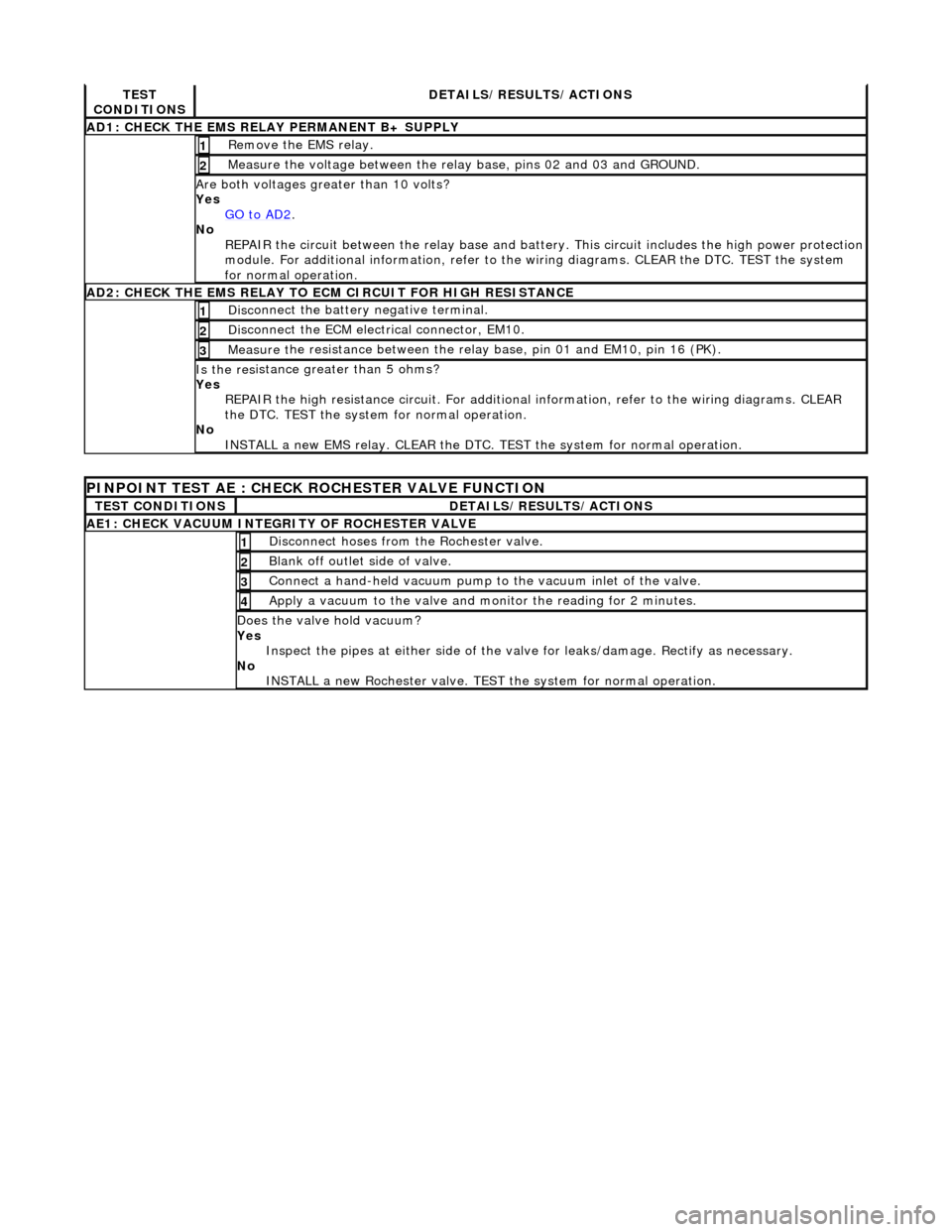
AD1
:
CHECK THE EMS RELAY PERMANENT B+ SUPPLY
R
e
move the EMS relay.
1
Meas
ure t
he voltage between the rela
y base, pins 02 and 03 and GROUND.
2
Are both vol
tages greater than 10 volts?
Yes GO to AD2
.
No
R
EPAIR the circuit between the rela
y base and battery. This circuit includes the high power protection
module. For additional information, refer to the wiring diagrams. CLEAR the DTC. TEST the system
for normal operation.
AD2 :
CHECK THE EMS RELAY TO ECM CIRCUIT FOR HIGH RESISTANCE
Di
sc
onnect the battery negative terminal.
1
D
i
sconnect the ECM electrical connector, EM10.
2
Meas
ure t
he resistance between the rela
y base, pin 01 and EM10, pin 16 (PK).
3
Is the res
istance greater than 5 ohms?
Yes REPAIR the high resistance circui t. For additional information, refer to the wiring diagrams. CLEAR
the DTC. TEST the system for normal operation.
No INSTALL a new EMS relay. CLEAR the DTC. TEST the system for normal operation.
PINPOINT TEST AE : CHECK
ROCHESTER VALVE FUNCTION
T
E
ST CONDITIONS
D
E
TAILS/RESULTS/ACTIONS
AE1: CHEC
K VAC
UUM INTEGRITY OF ROCHESTER VALVE
Di
sc
onnect hoses from the Rochester valve.
1
Bl
a
nk off outlet side of valve.
2
Con
n
ect a hand-held vacuum pump to the vacuum inlet of the valve.
3
Appl
y a vacuum t
o the valve and mo
nitor the reading for 2 minutes.
4
Do
es the valve hold vacuum?
Yes Inspect the pipes at either side of the valve for leaks/damage. Rectify as necessary.
No INSTALL a new Rochester valve. TEST the system for normal operation.
Page 1237 of 2490
E
lectronic Engine Controls -
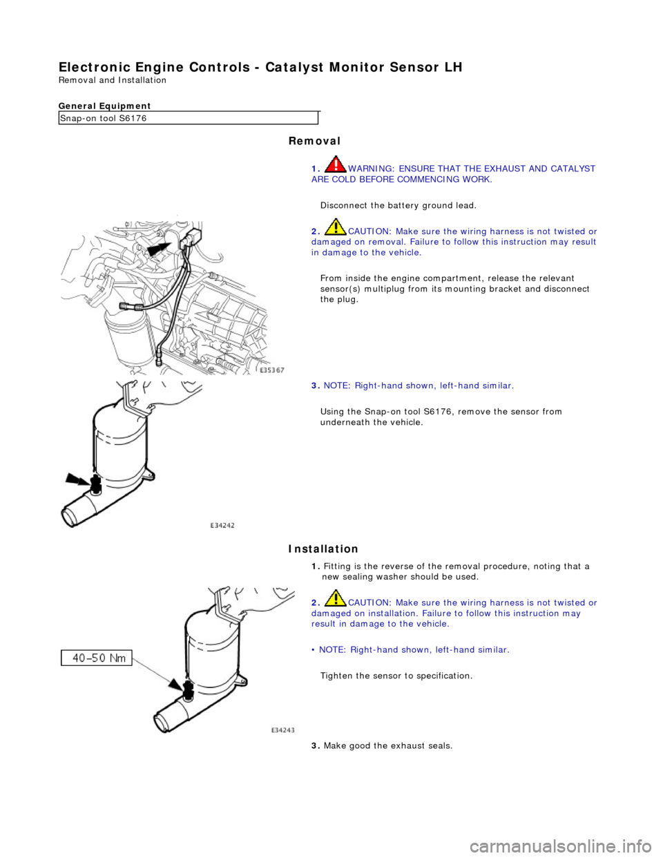
Catalyst Monitor Sensor LH
Re
moval and Installation
General Equipment
Remov
al
Installation
Snap
-on tool S6176
1. WARNING: ENSURE THAT THE EXHAUST AND CATALYST
ARE COLD BEFORE COMMENCING WORK.
Disconnect the battery ground lead.
2. CAUTI
ON: Make sure the wiring harness is not twisted or
damaged on removal. Failure to fo llow this instruction may result
in damage to the vehicle.
From inside the engine compartment, release the relevant
sensor(s) multiplug from its mounting bracket and disconnect
the plug.
3. NOTE
: Right-hand shown, left-hand similar.
Using the Snap-on tool S6176, remove the sensor from
underneath the vehicle.
1. Fitting is the reverse of the removal procedure, noting that a
new sealing washer should be used.
2. CAUTI
ON: Make sure the wiring harness is not twisted or
damaged on installation. Failure to follow this instruction may
result in damage to the vehicle.
• NOTE: Right-hand shown, left-hand similar.
Tighten the sensor to specification.
3. Make good th
e exhaust seals.
Page 1238 of 2490
El
ectronic Engine Controls -
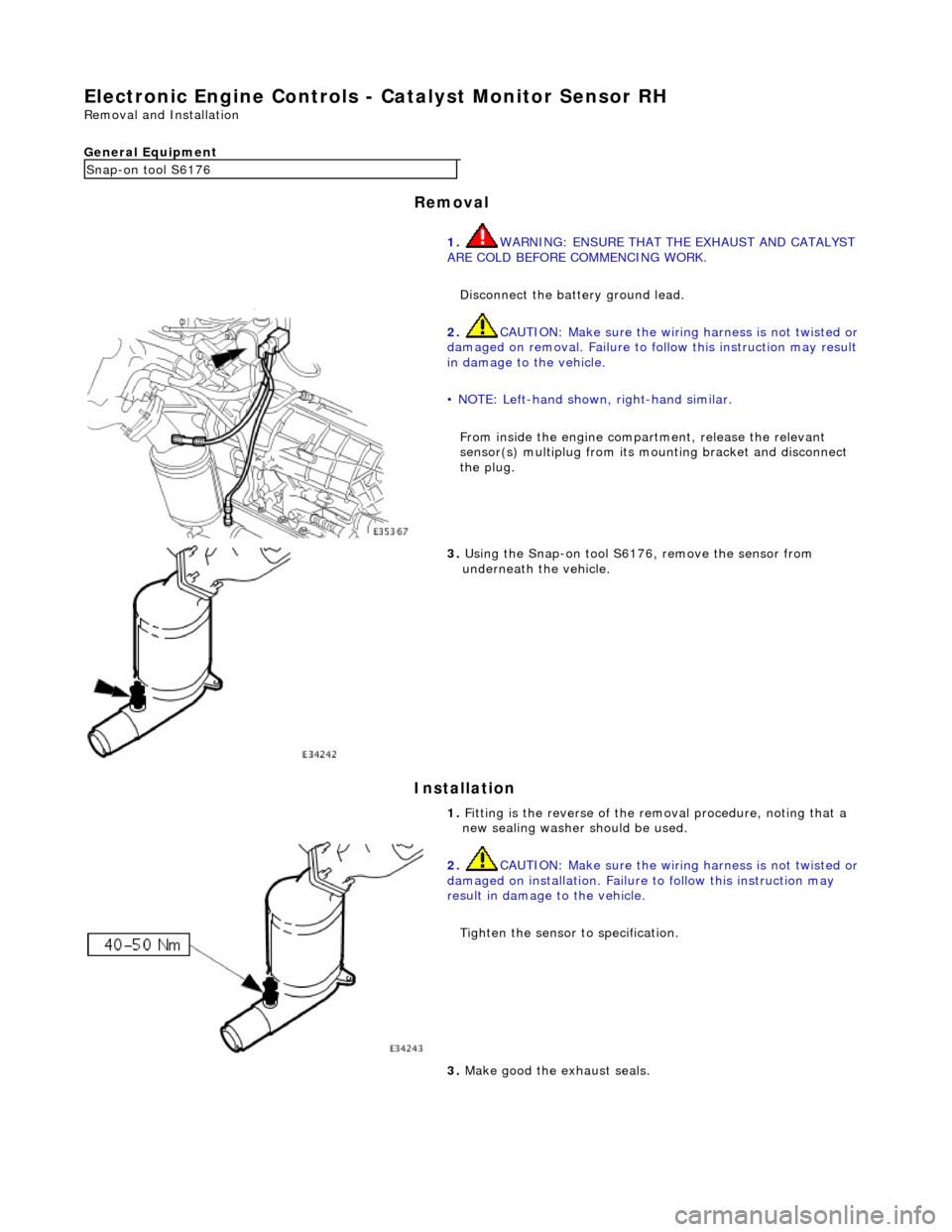
Catalyst Monitor Sensor RH
Remo
val and Installation
General Equipment
Remov a
l
Installation
Snap -
on tool S6176
1. WARNING: ENSURE THAT THE EXHAUST AND CATALYST
ARE COLD BEFORE COMMENCING WORK.
Disconnect the battery ground lead.
2. CAUTIO
N: Make sure the wiring harness is not twisted or
damaged on removal. Failure to fo llow this instruction may result
in damage to the vehicle.
• NOTE: Left-hand shown, right-hand similar.
From inside the engine compartment, release the relevant
sensor(s) multiplug from its mounting bracket and disconnect
the plug.
3. Us
ing the Snap-on tool S6176, remove the sensor from
underneath the vehicle.
1. Fitting is the reverse of the removal procedure, noting that a
new sealing washer should be used.
2. CAUTI
O
N: Make sure the wiring harness is not twisted or
damaged on installation. Failure to follow this instruction may
result in damage to the vehicle.
Tighten the sensor to specification.
3. Make good th e exh
aust seals.
Page 1249 of 2490
Electron
ic Engine Controls -
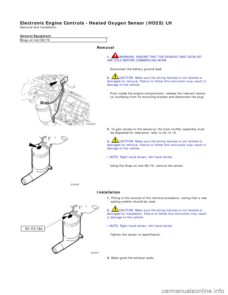
Heated Oxygen Sensor (HO2S) LH
Rem
oval and Installation
General Equipment
Remov
al
Installation
Snap
-on tool S6176
1. WARNING: ENSURE THAT TH E EXHAUST AND CATALYST
ARE COLD BEFORE COMMENCING WORK
Disconnect the battery ground lead.
2.
CAUTION: Make sure the wiring harness is not twisted or
damaged on removal. Failure to follow this instruction may result in
damage to the vehicle.
From inside the engine compartm ent, release the relevant sensor
(s) multiplug from its mounting bracket and disconnect the plug.
3.
To gain access to the sensor(s) the front muffler assembly must
be displaced for clearance; refer to 30.10.18.
4.
CAUTION: Make sure the wiring harness is not twisted or
damaged on removal. Failure to follow this instruction may result in
damage to the vehicle.
• NOTE: Right-hand shown, left-hand similar.
Using the Snap-on tool S6176, remove the sensor.
1.
Fitting is the reverse of the remo val procedure, noting that a new
sealing washer should be used.
2.
CAUTION: Make sure the wiring harness is not twisted or
damaged on installation. Failure to follow this instruction may result
in damage to the vehicle.
• NOTE: Right-hand shown, left-hand similar.
Tighten the sensor to specification.
3.
Make good the exhaust seals.
Page 1250 of 2490
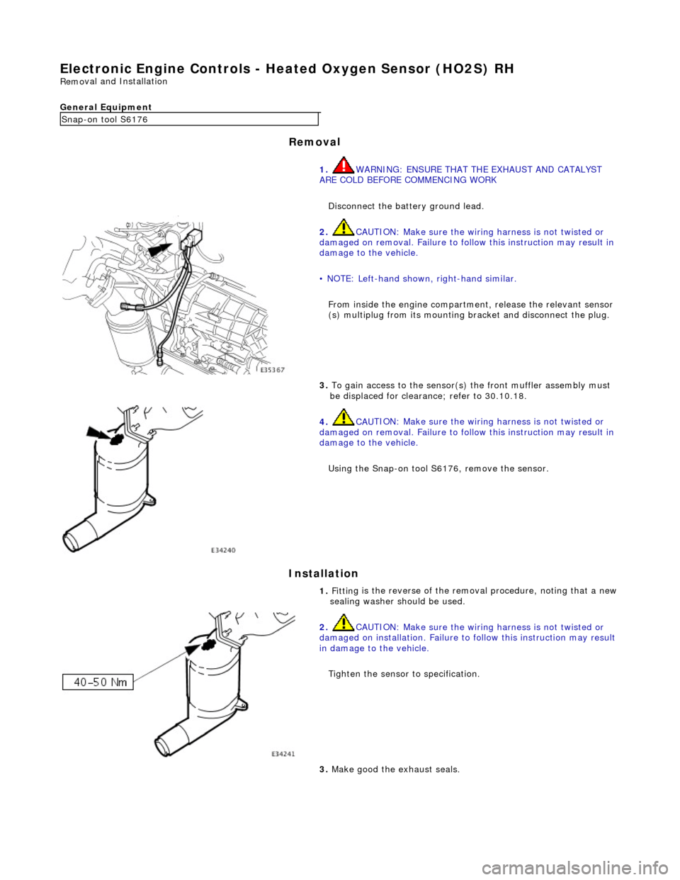
Electronic
Engine Controls -
Heated Oxygen Sensor (HO2S) RH
Remo
val and Installation
General Equipment
Remov a
l
Installation
Snap -on to
ol S6176
1. WARNING: ENSURE THAT TH E EXHAUST AND CATALYST
ARE COLD BEFORE COMMENCING WORK
Disconnect the battery ground lead.
2. CAU
TION: Make sure the wiring harness is not twisted or
damaged on removal. Failure to follow this instruction may result in
damage to the vehicle.
• NOTE: Left-hand shown, right-hand similar.
From inside the engine compartm ent, release the relevant sensor
(s) multiplug from its mounting bracket and disconnect the plug.
3. To
gain access to the sensor(s)
the front muffler assembly must
be displaced for clearance; refer to 30.10.18.
4. CAU
TION: Make sure the wiring harness is not twisted or
damaged on removal. Failure to follow this instruction may result in
damage to the vehicle.
Using the Snap-on tool S6176, remove the sensor.
1. Fittin
g is the reverse of the remo
val procedure, noting that a new
sealing washer should be used.
2. CAU
TION: Make sure the wiring harness is not twisted or
damaged on installation. Failure to follow this instruction may result
in damage to the vehicle.
Tighten the sensor to specification.
3. M
ake good the exhaust seals.
Page 1362 of 2490
Automatic Transmission/Transaxle - 4.0L NA V8 - AJ27/3.2L NA V8 - AJ26
- Transmission Intern al Wiring Harness
In-vehicle Repair
Removal
• NOTE: The temperature sensor is integral with the internal harness.
1. Disconnect battery ground cable.
Remove the battery cover.
2. Raise the vehicle on a lift.
2. WARNING: TRANSMISSION FLUID MAY CAUSE
SEVERE BURNS, ENSURE THAT ALL SAFETY PROCEDURES
ARE OBSERVED.
Carefully remove the drain plug and drain the
transmission fluid.
3. Remove the twenty-two bolts which secure the fluid pan.
Remove the fluid pan and all tr aces of gasket material.
4. Remove the input speed sensor.
• NOTE: M5 fixing. 1. Release the screw which secures the input speed sensor bracket and pull the sensor clear.
Disconnect harness multiplug.
Page 1367 of 2490
Automatic Transmission/Transaxle - 4.0L NA V8 - AJ27/3.2L NA V8 - AJ26
- Transmission Internal Wiring Harnes s Electrical Connector O-Ring Seals
In-vehicle Repair
Removal
1. Disconnect battery ground cable.
Remove the battery cover.
2. Raise the vehicle for access.
3. Remove the fluid pan; refer to 44.24.04.
4. Remove selector cable abutment bracket fixings (2) and
reposition the bracket for access to the multiplug.
5. Disconnect the transmission harness multiplug.
1. Release the harness locking lever.
2. Disconnect the harness multiplug.
6. Remove harness multiplug retaining clip.
Push the multiplug into the transmission casing to release.
Discard the two 'O' rings.
Page 1443 of 2490
Automatic Transmission/Transaxle - 4.0L SC V8 - AJ26 - Transmission
Internal Wiring Harness Electr ical Connector O-Ring Seals
In-vehicle Repair
Removal
1. Disconnect the batt ery ground cable.
2. Open the engine compartment and fit paint protection sheets.
3. Raise the vehicle for access.
4. WARNING: TRANSMISSION FLUID MAY CAUSE SEVERE
BURNS, ENSURE THAT ALL SAFET Y PROCEDURES ARE OBSERVED
AND THAT THE RECEPTACLE FOR WASTE HAS SUFFICIENT
CAPACITY.
Drain the transmission fluid.
Carefully remove the drain pl ug and discard the sealing
washer.
5. Remove the harness heatshield lower fixing.
Remove the screw heatshield / fluid pan clamp.
6. Remove the harness heatshield.
Pull the heatshield from under the clip.
7. Disconnect the transmission link harness connector.
1. Release the locking lever on the guide bush and disconnect the harness connector.