Page 2003 of 2490

WARNING: Do not use a naked flame in areas where fuel or oil have been spilt. Clean the area of residual oil
and fuel and wait un til the fuel spill has fully evaporated.
• CAUTIONS:
When using a heat source make sure that it is localised and caus es no damage to surrounding materials.
Where the repair procedure indicates that a glue lined heat shrink sleeve should be applied, apply sufficient
heat to the glue lined heat shrink to melt the glue in order to provide a water tight seal. Do not over heat the glue
lined heat shrink sleeve so that the wi ring harness insulation becomes damaged.
Using a suitable heat source, shrink the sleeve over the butt splice.
If further pre-terminated wiri ng harness(s) are to be installed to the sa me electrical connector, make sure that the
lead is cut at a different length to the previous joint. This makes sure that the splices will, where possible, be
staggered on the wiring ha rness and prevent a bulk of splices in one area.
When all of the splices have been made, fit the terminal(s) to the electrical connector, taking care that the terminals
are correctly orientated.
Install the wiring harness cove r and secure with adhesive electrical tape. Do not cove r the wiring harness right to the electrical connector as the terminals must have a little movement and no t be firmly bound to the electrical connector or wiring harness. Make sure that the cable identification sleeve(s) are showing at the wiring harness electrical
connector.
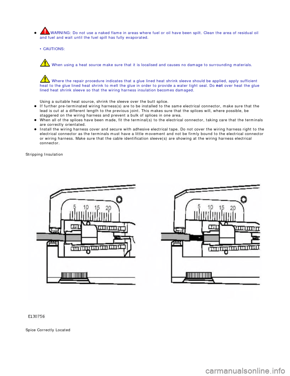
Stripping Insulation
Spice Correctly Located
Page 2005 of 2490
Wiring Harnesses - Wiring Harness Repair
General Procedures
1.
For additional information, refer to: Wiring Harness
(418-02
Wiring Harnesses, Description and Operation).
Page 2013 of 2490
Multifunction Electronic Modules - Multifunction Electronic Module
Diagnosis and Testing
Tests Using the Portable Diagnostic Unit
Refer to PDU User Guide
The complexity of the electronics involved with the various Electronic Control Modules and the multiplexed communication
networks, preclude the use of workshop general electrical test equipment. Therefore, reference should be made to the PDU
User Guide for detailed instructions on test ing control modules.
The PDU systematically test s and analyses the control modules and th e associated electrical connections.
Where a fault involving a control module is indicated by the PDU, before replacing the component, some basic diagnostic
methods may be necessary to confirm that connecti ons are good and that wiring is not damaged.