Page 638 of 2490

se
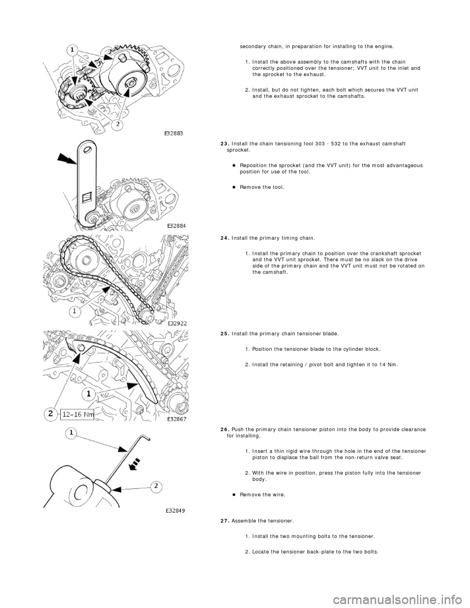
condary chain, in preparation for installing to the engine.
1. Install the above assembly to the camshafts with the chain correctly positioned over the tensioner; VVT unit to the inlet and
the sprocket to the exhaust.
2. Install, but do not tighten, each bolt which secures the VVT unit and the exhaust sprocket to the camshafts.
23 .
Install the chain t
ensioning tool 303 - 532 to the exhaust camshaft
sprocket.
Re p
osition the sprocket (and the VVT unit) for the most advantageous
position for use of the tool.
Re
move the tool.
24 . Install the
primary timing chain.
1. Install the primary chain to position over the crankshaft sprocket and the VVT unit sprocket. There mu st be no slack on the drive
side of the primary chain and the VVT unit must not be rotated on
the camshaft.
25 . Install the pri
mary chain tensioner blade.
1. Position the tensioner blade to the cylinder block.
2. Install the retaining / pivot bolt and tighten it to 14 Nm.
26 . P
ush the primary chain tensioner piston into the body to provide clearance
for installing.
1. Insert a thin rigid wire through the hole in the end of the tensioner
piston to displace the ball from the non-return valve seat.
2. With the wire in position, press the piston fully into the tensioner body.
Rem
ove the wire.
27. Assemble the tensioner.
1. Install the two mounting bolts to the tensioner.
2. Locate the tensioner back-plate to the two bolts.
Page 644 of 2490
15. Di
sconnect the air cleaner cover.
R
e
lease the five clips which se
cure the air cleaner cover.
16. Disconnect the air flow meter multi-plug.
17 . R
emove the intake tube / air
flow meter / air cleaner cover
assembly.
1. Remove the intake tube / air flow meter / air cleaner
cover assembly.
2. Remove and discard the ru bber seal; air intake tube
to throttle body.
18. Remove the purge valve, fro m the evaporative control
system. Refer to Operation 17.45.01.
19. Remove the on-plug ignition coils. Refer to Operation
18.20.41 and 18.20.42.
20. Remove the camshaft covers. Refer to Operations 12.29.43
and 12.29.44.
21. Remove the variable valve ti ming solenoids. Refer to
Operation18.30.63.
22. Disconnect the engine harness retaining clips from the timing
cover.
Page 648 of 2490
8. Re
fit the variable valve timing
solenoids. Refer to Operation
18.30.63.
9. Refit the camshaft covers. Refer to Operations 12.29.43.and
12.29.44.
10. Refit the on-plug ignition coils and coil covers. Refer to
Operation 18.20.41 and 18.20.42.
11. Refit the purge valve. Refer to Operation 17.45.01.
12 . F
it the intake tube / air flow meter / air cleaner cover
assembly.
1. Fit a new rubber seal; air in take tube to throttle body.
2.
Fit the intake tube / air
flow meter / air cleaner cover
assembly.
13 . R
econnect the air cleaner cover.
F
it
the five clips which secu
re the air cleaner cover.
14. Co
nnect the intake tube to the throttle body.
1. Connect the intake tube to the throttle body.
2. Fit the two bolts which secure the intake tube to the throttle body.
Page 653 of 2490
15
.
Disconnect the air cleaner cover.
R
elease the five clips which se
cure the air cleaner cover.
16. Disconnect the air flow meter multi-plug.
17
.
Remove the intake tube / air flow meter / air cleaner cover
assembly.
1. Remove the intake tube / air flow meter / air cleaner
cover assembly.
2. Remove and discard the ru bber seal; air intake tube
to throttle body.
18. Remove the purge valve, fro m the evaporative control
system. Refer to Operation 17.45.01.
19. Remove the on-plug ignition coils. Refer to Operation
18.20.41 and 18.20.42.
20. Remove the camshaft covers. Refer to Operations 12.29.43
and 12.29.44.
21. Remove the variable valve ti ming solenoids. Refer to
Operation18.30.63.
22. Disconnect the engine harness retaining clips from the timing
cover.
Page 657 of 2490
7. Reposition and secure the engine harness clips to the timing
cover.
8. Refit the variable valve timing solenoids. Refer to Operation
18.30.63.
9. Refit the camshaft covers. Refer to Operations 12.29.43.and
12.29.44.
10. Refit the on-plug ignition coils and coil covers. Refer to
Operation 18.20.41 and 18.20.42.
11. Refit the purge valve. Refer to Operation 17.45.01.
12. Fit the intake tube / air flow meter / air cleaner cover
assembly.
1. Fit a new rubber seal; air in take tube to throttle body.
2. Fit the intake tube / air flow meter / air cleaner cover
assembly.
Page 661 of 2490
2. Fit the camshaft caps to their respective locations (5 to 9 from the front) and in the correct orientation
(arrow to front of engine).
3. Fit and tighten the cap securing bolts. Tighten evenly,
in stages, to 9 - 11 Nm.
3. Fit the camshaft locking tool 303 - 530 (fitted for following
operation) align the camshaft as necessary.
4. Refit Exhaust Camshaft Sprocket . Refer to Operation 12.65.74.
5. With the camshaft (303 - 530) and crankshaft (303 - 531)
setting tools removed, after the previous operation, adjust the
valve clearances on the exhaus t camshaft. refer to Operation
12.29.48.
6. Move the engine compartment co ver from the service position
and connect the gas struts.
7. Remove the paint protection sheets and close the cover.
8. Connect the battery and fit the battery cover.
Refer to the Battery Reconnection Procedure 86.15.15.
Page 663 of 2490
2. Fit the camshaft caps to their respective locations (5 to 9 from the front) and in the correct orientation
(arrow to front of engine).
3. Fit and tighten the cap securing bolts. Tighten evenly,
in stages, to 9 - 11 Nm.
3. Fit the camshaft locking tool 303 - 530 (fitted for following
operation) align the camshaft as necessary.
4. Refit Exhaust Camshaft Sprocket . Refer to Operation 12.65.73.
5. With the camshaft (303 - 530) and crankshaft (303 - 531)
setting tools removed, after the previous operation, adjust the
valve clearances on the exhaus t camshaft. refer to Operation
12.29.48.
6. Move the engine compartment co ver from the service position
and connect the gas struts.
7. Remove the paint protection sheets and close the cover.
8. Connect the battery and fit the battery cover.
Refer to the Battery Reconnection Procedure 86.15.15.
Page 666 of 2490

Installation
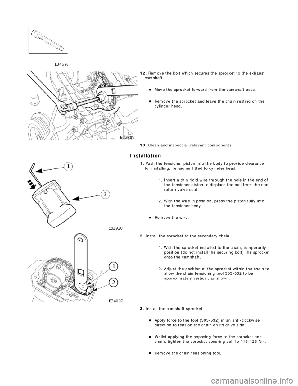
12. Remove the bolt which secures the sprocket to the exhaust
camshaft.
Move the sprocket forward from the camshaft boss.
Remove the sprocket and leav e the chain resting on the
cylinder head.
13. Clean and inspect all relevant components.
1. Push the tensioner piston into the body to provide clearance
for installing. Tensioner fitted to cylinder head.
1. Insert a thin rigid wire th rough the hole in the end of
the tensioner piston to displace the ball from the non-
return valve seat.
2. With the wire in position, press the piston fully into the tensioner body.
Remove the wire.
2. Install the sprocket to the secondary chain.
1. With the sprocket installe d to the chain, temporarily
position (do not install the securing bolt) the sprocket
onto the camshaft.
2. Adjust the position of the sprocket within the chain to
allow the chain tensioning tool 303-532 to be
approximately vertical, as shown.
3. Install the cams haft sprocket.
Apply force to the tool (303-532) in an anti-clockwise
direction to tension the chain on its drive side.
Whilst applying the opposing force to the sprocket and
chain, tighten the sprocket securing bolt to 115-125 Nm.
Remove the chain tensioning tool.