Page 2317 of 2490
9. Slacken and remove two bolts securing throttle cable
adjustment bracket to throttle body.
10. Release locking clips and sl acken and remove the three
screws securing bottom of motor housing to bulkhead.
11. Slacken and remove three bo lts securing top of motor
housing to bulkhead.
12. Holding the purge valve bracket and capillary clear, carefully
withdraw housing complete with motor, and linkage assembly.
13. Remove and discard inner seal from motor spindle.
14. Slacken and remove two nuts and bolts securing motor to
housing and remove motor.
Page 2318 of 2490

Installation
1.
Position motor in housing and fi t and tighten securing nuts and
bolts.
2. Apply suitable lubricant to bore of new spindle inner seal and
fit seal over motor spindle.
3. Holding the capillary and purge valve clear, position
motor/housing assembly on bulkhead.
4. Seat motor spindle seal correctly in upper plenum aperture and
ensure that housing lo cates on lower studs.
5. Fit and tighten the housin g upper securing bolts.
6. Fit and tighten the housing lower securing screws and slide
locking clips inwards.
7. Position throttle cable adjustment bracket on throttle body and
fit and tighten securing bolts.
8. Position purge valve bracket at bulkhead and fit and tighten
securing bolt and nuts.
9. Position engine harness multiplu g on mounting bracket and fit
and tighten securing nut.
10. Connect motor harness multiplug and locate in retaining clip.
11. Apply suitable lubricant to bore of new outer seal and fit with
washer to motor spindle.
12. Fit and fully tighten collar nut on motor spindle.
13. Fit plenum cover. Refer to 76.10.01.
14. Fit wiper arm and blade. Refer to 84.15.44.90.
15. Fit top covers to LH and RH bulkheads and rear of engine
compartment. refer to 76.11.33 and 76.11.35.
16. Fit ground cable to battery te rminal and cover to battery.
Refer to 86.15.15.
Page 2319 of 2490
Wipers and Washers - Windshield Wiper MotorVehicles Built From:
10/1997
Removal and Installation
Removal
1. Remove battery cover and disc onnect ground cable from
battery terminal. Refer to 86.15.19.
2. Remove top covers from LH an d RH bulkheads and rear of
engine compartment. Refer to 76.11.33 and 76.11.35.
3. Remove wiper arm and blade as sembly. Refer to 84.15.44.90.
4. Remove plenum cover. Refer to 76.10.01
5. Remove motor harness multiplug from clip, disconnect
multiplug and position harness clear of clip.
6. Slacken and remove nut securi ng wiper spindle to top of
plenum, remove washer and seal and discard seal.
7. Slacken and remove nut securing engine harness main
multiplug to mounting bracke t and position multiplug for
access.
8. Slacken and remove two nuts an d bolt securing purge valve
mounting bracket to bulkhead and position assembly for
access.
Page 2320 of 2490

Installation
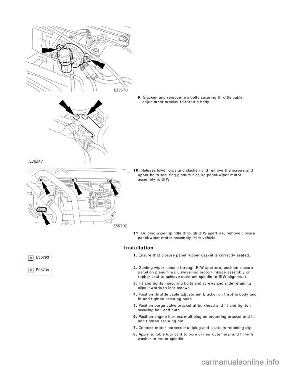
9. Slacken and remove two bolts securing throttle cable
adjustment bracket to throttle body.
10. Release lower clips and slacken and remove the screws and
upper bolts securing plenum closure panel/wiper motor
assembly to BIW.
11. Guiding wiper spindle through BIW aperture, remove closure
panel/wiper motor assembly from vehicle.
E357931. Ensure that closure panel rubbe r gasket is correctly seated.
E357942. Guiding wiper spindle through BI W aperture, position closure
panel on plenum wall, swivelling motor/linkage assembly on
rubber seat to achieve optimu m spindle to BIW alignment.
3. Fit and tighten securing bolts and screws and slide retaining
clips inwards to lock screws.
4. Position throttle cable adjustment bracket on throttle body and
fit and tighten securing bolts.
5. Position purge valve bracket at bulkhead and fit and tighten
securing bolt and nuts.
6. Position engine harness multiplu g on mounting bracket and fit
and tighten securing nut.
7. Connect motor harness multiplug and locate in retaining clip.
8. Apply suitable lubricant to bore of new outer seal and fit with
washer to motor spindle.