Page 1785 of 2490
Engine speed (valve closed with the engine not running) Demand (set) temperature In-car temperature sensor Solar sensor
Re-heating of the refrigerated air is contro lled by the time that the water valve is open (i.e. not energised) over a six secon d
interval. The duty cycle of the water valve, the time open / time closed, is controlled by the A/CCM.
Maximum heating demand will cause the water valve to be fu lly open (not energised) to allow maximum coolant flow
through the heater matrix.
At Maximum cooling, the water va lve will be fully closed (energised) to prevent hot (engine temperature) coolant entering
the heater circuit; the pump however will continue to circulate coolant through both the heater matrix and water valve
bypass.
The water valve defaults open when the ignition is OFF.
Under engine stall conditions, when ignition is ON, the water valve will be open.
Water Pump Assembly
Located in the same area as the water valve, the water pump continually circulates coolant through the heater matrix
except when the conditions below apply:
The engine coolant is below 16°C. The ignition is OFF. Under engine stall conditions, when ignition is ON. Control panel OFF
Non return valves
The heater bypass hose has a non-return valve, located between the engine feed and return hoses. The valve prevents the
water pump from recirculating coolant fro m the heater at low engine speeds.
The flow indicator arrow embossed on the valve bo dy MUST point towards the coolant header tank.
CAUTION: Coolant flow will be compromi sed if either valve is fitted incorrectly. Observe the correct direction.
A second non-return valve is located betw een the water pump and water valve. This valve prevents hot coolant from flowing
into the heater with the engine switched off. The flow indicator arrow MUST point towards the water pump.
Heater feed and return hoses
The heater feed and return hoses are connected to the engine feed and return hoses by 'Quick-Fit' connection unions. The
feed hose has a Norma R20 connector and the return hose a Norma push and seal connector. The coolant system bleed
joints have Cobra clamps. All remaining hose connections have spring band hose clamps.
The engine feed hose is connected to the engine bypass hous ing and the engine return hose is connected to the engine
water pump.
Clamp Identification
Page 1798 of 2490
Air Conditioning - Air Conditioning
Description and Operation
Introduction
Parts List
The climate control system features fully automatic control of temperature, blower speed (airflow) and air distribution to
maintain optimum comfort under most driving conditions.
Manual controls are provided to allow the operator to over-ride automatic operation.
System Features
ItemPart NumberDescription
1—Fascia panel with integral ducting
2—Heater / cooler assembly
3—A/CCM
4—Blower LH and RH
5—Plenum
6—Control panel
7—Solar sensor
8—Assembly valve - water
9—Assembly pump - water
10—Temperature sensor - external
11—Compressor
12—Pressure switch - 4 level
13—Motorized in-car aspirator (LHD shown)
14—Receiver drier
15—Condenser
Page 1799 of 2490
Twin blower assemblies Center mounted evaporator, heater and air distribution unit Electric solenoid water valve controlled heating Electric water pump assembly Servo motor driven air distribution flaps Dedicated side glass defrost / demist vents External temperature sensor Motorised in-car aspirator Solar sensor
Electronic Control Panel
Liquid Crystal Display (LCD) Digital temperature display Manual fan speed level External temperature display Celsius / Fahrenheit selection Heated windshield switch (where fitted) Heated backlight switch Defrost switch Manual airflow distribution overrides (4) Access to self diagnostic system and error codes
Sensors
External ambient temperature sensor Motorized in-car aspirator Heater matrix temperature sensor Evaporator temperature sensor Solar sensor
These sensors feedback information to the Air Conditioning Control Module (A/CCM) which automatically adjusts air
temperature, airflow volume and distributi on from the air conditioning unit to maintain a stable passenger compartment
average temperature under changing weather conditions.
Major Components
Page 1800 of 2490
Compressor:
Features
Engine mounted, driven by the accessory drive belt. Fixed displacement type. High-pressure relief valve, to avoid system over-pressure. ECM controlled clutch energized via a relay.
Receiver drier:
Vertically mounted on the ri ght-hand side of the engine compartment next to the engine coolant radiator. Fitted with the high-side charge port. Includes a fluorescent tracer dye me chanism to aid leak detection.
ItemPart NumberDescription
1—Compressor assembly
2—Condenser
3—Evaporator and heater matrix (internal)
4—Receiver drier
5—4-level pressure switch
6—Expansion valve (internal)
7—High-side charge port
8—Low-side charge port
9—Suction muffler
10—Discharge hose
11—Discharge pipe
12—Suction hose
13—Suction pipe
14—Liquid line
15—Jumper hose (condenser hose)
Page 1801 of 2490
Condenser:
Multi-pass fin-over-tube type, mounted in front of the engine cooling pack and directly to the radiator.
Pressure (Bitron) switch:
Located in the discharge pipe. Provides a signal, via the A/CCM, to th e ECM, to disengage the compressor clut ch should the refrigerant pressure be
< 2 bar or > 30 bar.
Provides a hard-wired signal to the ECM, to switch the cool ing fans to HIGH speed at 22 bar rising pressure and to
LOW speed at 17,5 bar falling pressure.
Provides a hard-wired signal to the ECM, to switch the radiator cooling fans to LOW speed at 12 bar rising pressure
and to switch the fans OFF at 8 bar falling pressure.
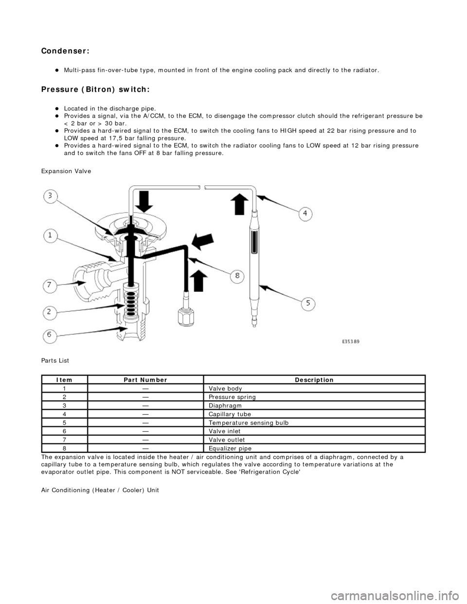
Expansion Valve
Parts List
The expansion valve is located inside the heater / air conditioning unit and comprises of a diaphragm, connected by a
capillary tube to a temperat ure sensing bulb, which regulates the valve according to temperature variations at the
evaporator outlet pipe. This component is NOT serviceable. See 'Refrigeration Cycle'
Air Conditioning (Heater / Cooler) Unit
ItemPart NumberDescription
1—Valve body
2—Pressure spring
3—Diaphragm
4—Capillary tube
5—Temperature sensing bulb
6—Valve inlet
7—Valve outlet
8—Equalizer pipe
Page 1803 of 2490
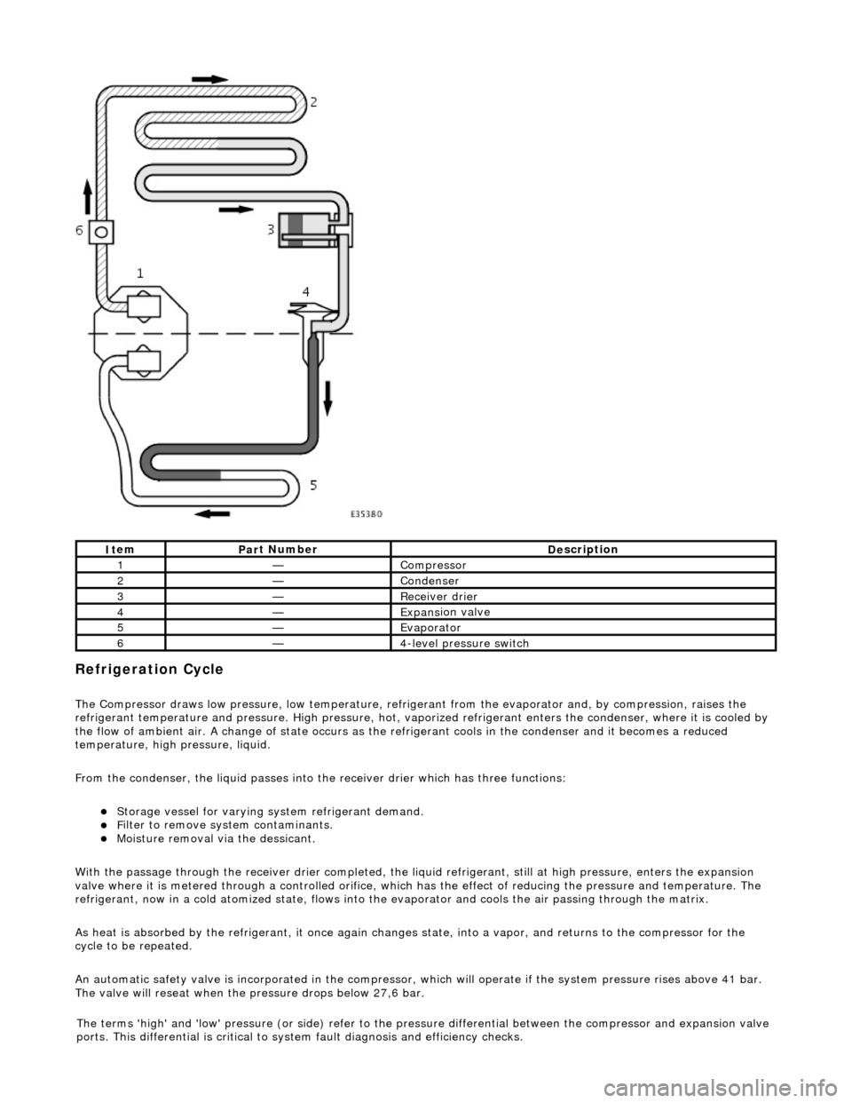
Refrigeration Cycle
The Compressor draws low pressure, lo
w te
mperature, refrigerant from the evaporat or and, by compression, raises the
refrigerant temperature and pressure. High pressure, hot, vaporized refr igerant enters the condenser, where it is cooled by
the flow of ambient air. A change of state occurs as the refrigerant cools in the condense r and it becomes a reduced
temperature, high pressure, liquid.
From the condenser, the liquid passes into the receiver drier which has three functions:
Storage vessel
for varying sy
stem refrigerant demand.
F
ilter to remove sy
stem contaminants.
Mo
isture removal via the dessicant.
With the passage through the receiver drie r completed, the liquid refrigerant, still at high pressure, enters the expansion
valve where it is metered through a contro lled orifice, which has the effect of reducing the pres sure and temperature. The
refrigerant, now in a cold atomized st ate, flows into the evaporator and cools the air passing through the matrix.
As heat is absorbed by the refrigerant, it once again changes state, into a vapor, and returns to the compressor for the
cycle to be repeated.
An automatic safety valve is incorporated in the compressor, which will operate if the system pressure rises above 41 bar.
The valve will reseat when the pressure drops below 27,6 bar.
It
em
Par
t Number
De
scription
1—Compre
ssor
2—Conden
ser
3—Re
ceiver drier
4—Expans
ion valve
5—Evaporator
6—4
-level pressure switch
The terms 'high' and 'low'
pressure (or si
de) refer to the pres sure differential betw een the compressor and expansion valve
ports. This differential is critical to sy stem fault diagnosis and efficiency checks.
Page 1826 of 2490
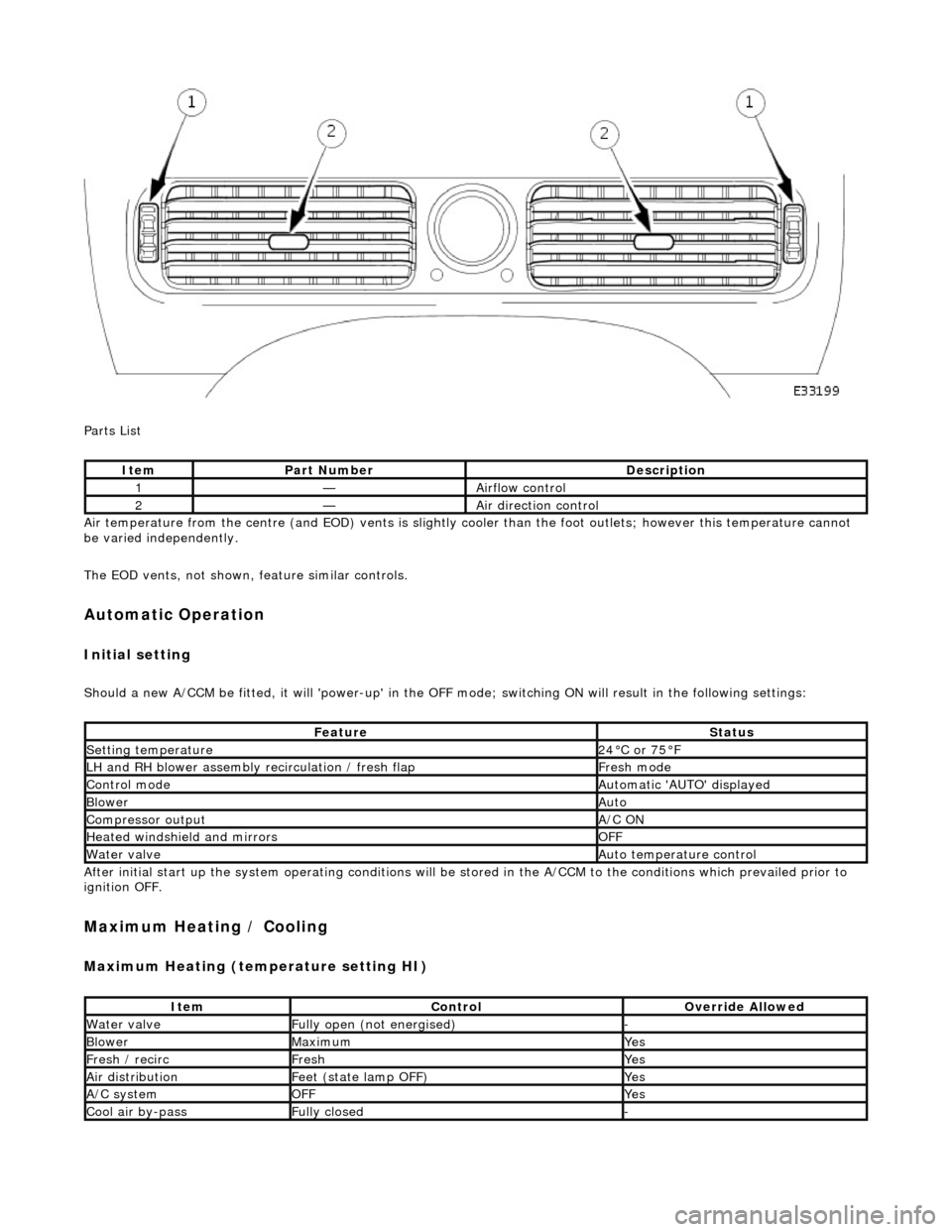
Parts List
Air temperature from the centre (and EOD) vents is slightly cooler than the foot outlets; however this temperature cannot
be varied independently.
The EOD vents, not shown, feature similar controls.
Automatic Operation
Initial setting
Should a new A/CCM be fitted, it will 'power-up' in the OFF mode; switching ON will result in the following settings:
After initial start up the system operating conditions will be st ored in the A/CCM to the conditions which prevailed prior to
ignition OFF.
Maximum Heating / Cooling
Maximum Heating (temperature setting HI)
ItemPart NumberDescription
1—Airflow control
2—Air direction control
FeatureStatus
Setting temperature24°C or 75°F
LH and RH blower assembly recirculation / fresh flapFresh mode
Control modeAutomatic 'AUTO' displayed
BlowerAuto
Compressor outputA/C ON
Heated windshield and mirrorsOFF
Water valveAuto temperature control
ItemControlOverride Allowed
Water valveFully open (not energised)-
BlowerMaximumYes
Fresh / recircFreshYes
Air distributionFeet (state lamp OFF)Yes
A/C systemOFFYes
Cool air by-passFully closed-
Page 1827 of 2490
Maximum Cooling (temperature setting LO)
Air Conditioning Control Module (A/CCM)
Location
The A/CCM is located on the right hand side of the air conditioning unit and controls all system functions.
The temperature within the passenger compartment is continually compared with the temperature selected on the control
panel LCD. The A/CCM receives data input signals and compares these with signal s from the system temperature sensors
and feedback devices. Based on this information the A/CCM adjusts the air outlet temperatur e, airflow and distribution from
the air conditioning system in to the passenger compartment.
Identification
ItemControlOverride Allowed
Water valveFully closed (energised)-
BlowerMaximumYes
Fresh / recircRecirculationYes
Air distributionFace (state lamp OFF)Yes
A/C systemONYes
Cool air by-passFully open-