Page 898 of 2490

ENSURE THAT ALL FIRE PREVENTION PROCEDURES ARE ACTIVE.
BEFORE PROCEEDING, IT IS ESSENTIAL THAT THE WARNING NOTES GIVEN IN SECTION 100-00 (UNDER THE
HEADING 'SAFETY PRECAUTIONS') ARE READ AND UNDERSTOOD.
9. Depressurise the fuel system.
Ensure that the ignition is switched off and remove the
valve cap from the fuel cross-over pipe. Place a cloth
under the valve to collect any spillage.
Place a closed container, su itable for collecting fuel,
adjacent to the vehicle. Remove the lid.
10. Connect the fuel injection pressure test equipment 310 - 058
(or other suitable type). Insert the drain / bleed tube into the
fuel container. Follow the ma nufacturer's instructions and
depressurise the fuel system.
11. Store the drained fuel safely and ensure that the lid is closed
securely. Remove the equipmen t and discard the cloth from
beneath the valve. Refit the valve cap.
12. Disconnect the breather pipe from the A-Bank camshaft
cover.
1. Disconnect the breather pipe from the stub pipe.
2. Remove and discard the O-ring seal from the breather
pipe.
13. Disconnect the air flow meter multi-plug.
14. Cut and remove the strap which secures the vacuum pipe to
the induction elbow.
15. Disconnect the intake tube from the throttle body.
1. Remove the two bolts which secure the intake tube to the throttle body.
2. Disconnect the intake tube from the throttle body.
Page 948 of 2490
Ig
nition switch to position 0
1
R
e
move intercooler
coolant pump relay
Inside EC
M housing
2
Ignition switc
h
to position II
3
Ch
e
ck for battery voltage at relay socket between pins 3
and 2.
4
B+ ?
Yes
GO to D6
No GO to D4
D4: C H
ECK RELAY SOCKET SUPPLY CONTINUITY
•
NOTE: Install fuse F2.
Do not replace relay.
Page 951 of 2490
Ignition switc
h to position II
1
Meas
ure voltage between relay socket between pin 2 and
ground EM017.
2
B+ ?
Yes
GO to D8
No GO to D7
D7: C
HECK ECM SUPPLY TO RELAY CONTINUITY
Page 954 of 2490
Allow at least 2 minutes f
or ai
r to purge from the system.
Top up the he
ader tank as re
quired and fit the pressure
cap.
2. Switch on the ignition, switch off the climate control system
and start the engine.
3. Run the engine at between 1500 and 2000 rpm until the
cooling fans operate.
4. Switch on the A/C system, set to maximum heat, and check
that heat is coming from the heat er at the fascia vents or the
footwell outlets.
5. Switch off the engine and allow it to cool down.
6. When cool, remove the pressure cap and top up the system as
necessary at the header tank.
7. If n e
cessary, fit new seals to the pressure cap.
1. Remove both O-rings from the pressure cap.
Fit and
fully seat new O-rings to the pressure cap.
8. Fit the pressure cap.
9. Remove the paintwork protection sheets and close the engine
cover.
Page 956 of 2490

• NOTE
: To ensure that
air is not drawn into the system during the following operations:
Do
not remove the cap from the header tank whilst the
charge air cooling system is open to atmosphere.
Do
not switch on the ignition when th
e charge air cooling system is open to atmosphere because the electrical
cooling pump may draw air into the system.
2. Fi
ll the cooling system at the header tank until the
level stabilises near the to p of the charge air cooler
fill point. This will take some time, as air is being
purged from the system.
Ensure that the head
er tank is full.
2. Fit the pressure cap to the header tank.
3. Pour coolant careful l
y into the charge air cooler fill point until
the system is full.
Fi t t
he plug and washer to the fill point.
4. Remove the pressure cap from the header tank.
5. Switch on the ignition and switch off the climate control
system.
Le ave
the ignition switched on (do not start the engine)
for at least 2 minutes to allow the air charge cooler
electric water pump to oper ate and to purge any air from
the air charge cooler radiator to the header tank. (This
operation will be repeated later)
6. Switch off the ignition for at least 1 minute.
7. Leave the ignition switched on (do not start the engine) for at
least 2 minutes to allow the air charge cooler electric water
pump to operate and to purg e any air from the air charge
cooler radiator to the header tank.
8. Top up the cooling system.
1. Top up the header tank and fit the pressure cap.
2. Remove the plug from the air charge cooler fill point. Pour coolant carefully into the air charge cooler fill
point until the system is full.
3. Fit the plug and washer to the fill point.
Page 962 of 2490

All vehicles
21.
N
OTE: Install a new sealing washer.
• NOTE: Clean off any spillages.
Install the supercharger coolant fill plug.
Tighte
n to 45 Nm.
22. Remove the coolant expans ion tank pressure cap.
23. Switch ignition on.
24. CAUTION: Do not allow the supercharger water pump to
run dry. Failure to follow this instruction may result in damage to
the vehicle.
• NOTE: Leave the ignition switched on (do not start the engine)
for at least 2 minutes to allow the air charge cooler electric water
pump to operate and to purge an y air from the air charge cooler
radiator to the header tank.
Allow the supercharger pump to run and top up the system
through the coolant expansion tank.
25 . Swit
ch the ignition off.
26. Install the coolant expansion tank pressure cap.
27. START and RUN the engine.
28. CAUTION: Observe the engine temperature gauge. If
the engine starts to over-heat switch off immediately and allow to
cool. Failure to follow this inst ruction may cause damage to the
vehicle.
Run the engine at between 1500 and 2000 rpm until the cooling
fan operates.
29 .
Swi
tch off the engine.
30. Allow the engine to cool.
31. Check and top-up the coolant if required.
Page 1012 of 2490

In
stallation
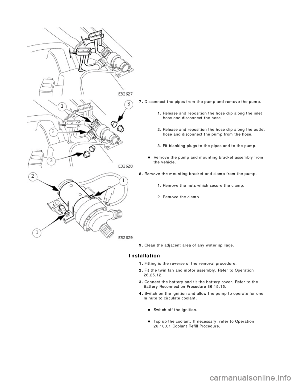
7.
Disc
onnect the pipes from the
pump and remove the pump.
1. Release and reposition th e hose clip along the inlet
hose and discon nect the hose.
2. Release and reposition the hose clip along the outlet
hose and disconnect th e pump from the hose.
3. Fit blanking plugs to the pipes and to the pump.
Remove t
he pump and mounting bracket assembly from
the vehicle.
8. Remove the moun
ting bracket and clamp from the pump.
1. Remove the nuts which secure the clamp.
2. Remove the clamp.
9. Clean the adjacent area of any water spillage.
1. Fitting is the reverse of the removal procedure.
2. Fit the twin fan and motor assembly. Refer to Operation
26.25.12.
3. Connect the battery and fit the battery cover. Refer to the
Battery Reconnection Procedure 86.15.15.
4. Switch on the ignition and allow the pump to operate for one
minute to circulate coolant.
Swit ch
off the ignition.
Top up th
e coolant
. If ne
cessary, refer to Operation
26.10.01 Coolant Refill Procedure.
Page 1020 of 2490

Fuel Char
ging and Controls - Fuel Charging and Controls
D
iagn
osis and Testing
I
n
spection and Verification
1.
1. Veri fy the customer concern.
2. 2. Confi
rm which, if any, warning li
ghts and/or messages were displayed on the instrument cluster.
• NOTE: If any warning lights and/or me ssages were displayed when the fault occurred, refer to the Driver Information
table for DTCs associated with the display, then to the DTC index table for possible sources and actions. Some warnings will
appear to clear when the ignition is cycl ed. This is often because the warning has flagged as a resu lt of one of the vehicle's
on-board diagnostic routines having run to detect the fault. If the same routine is not run when the ignition is switched ON,
the warning will not reflag until the routine does run. See the DTC summaries for drive cycle routines.
3. 3. Visually inspect for obvious signs of mechanical or electrical damage.
Vi
sual Inspection Chart
4.
4. Veri fy the foll
owing syst
ems are working correctly:
Air intake
system
Cooling system
Charging system
5. 5. If
an obvious cause for an observed or
reported concern is found, correct th e cause (if possible) before proceeding
to the next step.
6. 6. Where the Jaguar approved diagnostic sy stem is available, complete the S93 report before clearing any or all fault
codes from the vehicle.
• NOTE: If a DTC cannot be cleared, then there is a permanent fault present that flag s again as soon as it is cleared (the
exception to this is P1260, which will only clear following an ignition OFF/ON cycle after rectification).
7. 7. If the cause is not visually evident and the Jaguar approv ed diagnostic system is not available, use a fault code
reader to retrieve the fault codes be fore proceeding to the Diagnostic Trou ble Code (DTC) Index Chart, or the
Symptom Chart if no DTCs are set.
• NOTE: If the DTC flagged was not present for two or more co nsecutive cycles, it is classed as temporary, and will be
deleted following three cycl es during which no fault was present. This could result in a reported wa rning light/message with
no stored DTCs. If a fault is present for three consecutive cycles, the DTC becomes permanent, and will remain in the
module's memory for 40 drive cycl es (a cycle is an ignition OFF/ON, which will occur during the owner's normal use of the
vehicle. No action on the part of the technician is necessary to perform this cycle. A drive cycle is a series of conditions
needed to make the on-board diagnostic ro utine run, and may need a specific action on the part of the technician. See the
DTC summaries for drive cycle routines).
8. 8. Using the Jaguar approved diagnostic system where available, and a scan tool where not, check the freeze frame
data for information on the conditions applicable when the fault was flagged. The format of this will vary,
depending on the tool used, but can pr ovide information useful to the technician in diagnosing the fault.
MechanicalElectrical
Engine
oil level
Coo
ling system coolant
lev
el
Fuel contamination
Throttle body Poly-ve
e belt
Fu
ses
W
i
ring harness
E
l
ectrical connector(s)
Sens
o
r(s)
Engine
control module (E
CM)
Tran
s
mission control module
Check spark plu
g type. Only r
e
sisted plugs should be fitted. Refer to specifications
section for gap
Relay date codes. I
f the date on the rela
y is between R6 k1 and R6 k8, replace the
relay