Page 2041 of 2490
Body Closures - Fuel Filler Door Removal and Installation
Removal
Installation
1.
Remove battery cover and disconnect ground cable from battery
terminal. Refer to Section 86.15.19.
2. Remove fuel filler flap and hinge assembly.
1. Open filler flap
2. Remove fuel filler cap but do not stow on lid.
3. Slacken and remove the two filler flap hinge securing nuts and remove flap assembly from vehicle.
3. Using a flat-bladed screwdriver, carefully ease magnet snap-fit
mounting from filler flap.
4. Depress the filler flap striker retaining tang and remove the striker
assembly.
5. Remove and discard rubber buffer from filler flap.
1. Fit new rubber buffer to filler flap.
2. Fit striker to filler flap.
3. Ensure that magnet location is clean and snap-fit magnet to filler
flap.
4. Locate filler flap studs in hinge plate and fit and tighten securing
nuts.
5. Connect ground cable to battery terminal and fit battery cover.
Refer to Section 86.15.15.
Page 2103 of 2490

Exterior Trim and Ornamentation - Door Moulding
Removal and Installation
Removal
Installation
1.
Apply suitable protecti ve tape to immediately adjacent areas of
paintwork.
2. Using a hand-held heat gun, appply heat uniformly along
moulding length.
3. Applying local heat at one end and using a suitable thin lever
to avoid damaging paintwork, progressively ease moulding
away from door panel.
4. Discard moulding and remove protective tape.
5. Remove any residual adhesive and thoroughly clean area using
white spirit.
1. NOTE: Optimum adhesion is achi eved by warming body panel
and moulding to 65deg C.
Using white spirit ensure that mounting area is clean, dry and
de-greased.
2. Remove protective backing tape from moulding.
3. NOTE: Do not allow moulding to contact the body panel until it
is correctly aligned.
Heat moulding and moun ting area to 65degC.)
4. Aligning with adjacent mouldings or to match opposite side of
vehicle, press new moulding firmly onto body panel.
5. Apply hand pressure along moulding length to ensure
satisfactory adhesion.
6. Allow moulding and door panel to cool , then thoroughly clean
both using white spirit.
7. Apply a coat of suitab le polish to moulding and body panel.
Page 2104 of 2490

Exterior Trim and Ornamentation - Front Fender Moulding
Removal and Installation
Removal
Installation
1.
Apply suitable protecti ve tape to immediately adjacent areas of
paintwork.
2. Using a hand-held heat gun, appply heat uniformly along
moulding length.
3. Applying local heat at one end and using a suitable thin lever
to avoid damaging paintwork, progressively ease moulding
away from fender.
4. Discard moulding and remove protective tape.
5. Remove any residual adhesive and thoroughly clean area using
white spirit.
1. NOTE: Optimum adhesion is achi eved by warming body panel
and moulding to 65deg C.
Using white spirit ensure that mounting area is clean, dry and
de-greased.
2. Remove protective backing tape from moulding.
3. NOTE: Do not allow moulding to contact the fender until it is
correctly aligned.
Heat moulding and mounting area to 65deg C.
4. Aligning with adjacent mouldings or to match opposite side of
vehicle, press new mouldi ng firmly onto fender.
5. Apply hand pressure along moulding length to ensure
satisfactory adhesion.
6. Allow moulding and fender to cool , then thoroughly clean both
using white spirit.
7. Apply a coat of suitable poli sh to moulding and fender.
Page 2179 of 2490

Glass, Frames and Mechanisms - Glass, Frames and Mechanisms
Description and Operation
Fixed Glass
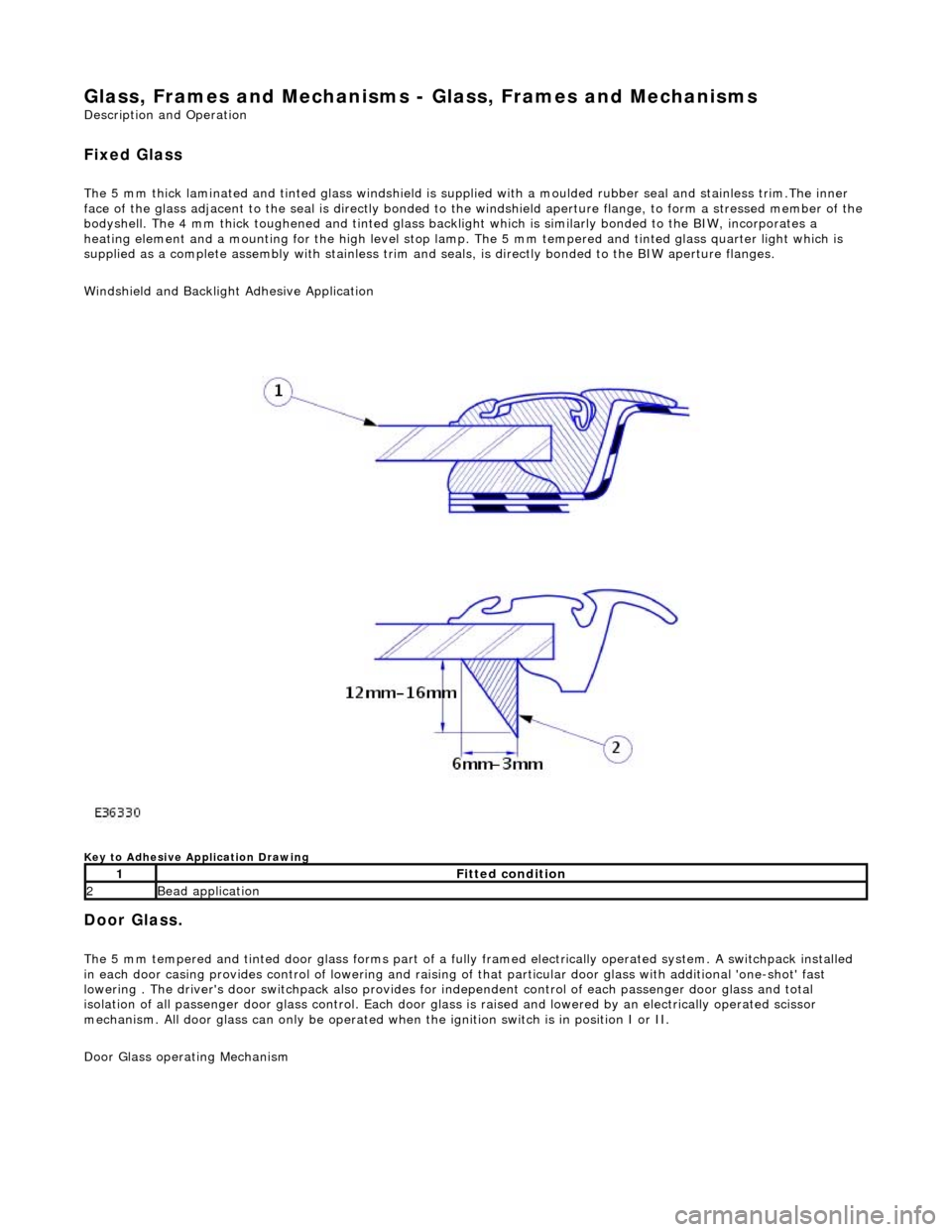
The 5 mm thick laminated and tinted glas s windshield is supplied with a moulded rubber seal and stainless trim.The inner
face of the glass adjacent to the seal is directly bonded to the windshield aperture flange, to form a stressed member of the
bodyshell. The 4 mm thick toughened and tinted glass backlight which is similarly bonded to the BIW, incorporates a
heating element and a mounting for the high level stop lamp. The 5 mm tempered and tinted glass quarter light which is
supplied as a complete assembly with stainless trim and seals, is directly bonded to the BIW aperture flanges.
Windshield and Backlight Adhesive Application
Key to Adhesive Application Drawing
Door Glass.
The 5 mm tempered and tinted door glass forms part of a fully framed electrically operated system. A switchpack installed
in each door casing provides control of lowering and raising of that particular d oor glass with additional 'one-shot' fast
lowering . The driver's door switchpack also provides for independent control of each passenger door glass and total
isolation of all passenger door glass control. Each door glas s is raised and lowered by an electrically operated scissor
mechanism. All door glass can only be operated wh en the ignition switch is in position I or II.
Door Glass operating Mechanism
1Fitted condition
2Bead application
Page 2244 of 2490
26. Remove steering column tilt adjustme nt motor harness
multiplug from retaining bracke t and disconnect multiplug.
27. Remove bolt securing facia moun ting bracket to RH side of
tunnel.
28. Remove facia RH end aperture trim pad.
29. CAUTION: The 'A' post facia mounting brackets are pre-
set to the body and must no t under any circumstances be
disturbed.
Remove two bolts securing facia to RH 'A' post mounting
bracket.
Page 2246 of 2490
35. From LH side footwell, remove nut securing facia harness
ground eyelet to tunnel front stud and disconnect eyelet from
stud.
36. Remove bolt securing facia moun ting bracket to LH side of
tunnel.
37. Remove bolt securing facia to bulkhead upper mounting
bracket (between air conditioni ng control and body processor
modules).
38. Remove facia LH end aperture trim pad.
Page 2247 of 2490
39. CAUTION: The 'A' post facia mounting brackets are pre-
set to the body and must no t under any circumstances be
disturbed.
Remove two bolts securing facia to LH'A' post mounting
bracket.
40. With assistance, carefully pull facia assembly rearwards,
withdrawing centre locating pin from front bulkhead and
disengaging side dowels from slots in'A' post brackets.
41. Remove facia assembly from vehicle and place on clean
bench correct way up, with back facing outward.
42. Disconnect key transponder module harness multiplug.
43. Remove key transponder module.
1. Remove two screws securi ng key transponder module
to facia and remove transponder module.
2. Remove and discard plastic inserts from facia steel
Page 2258 of 2490
31. Connect body processor module harness multiplug to facia
harness and tighten captive securing bolt.
32. Install illumination control module on facia. mounting.
1. Connect module to facia harness multiplug.
2. Slide module downward to secure on mounting bracket.
33. Install new key transponder module securing screw plastic
inserts to facia. Position key transponder module in facia and
install securing screws.
34. Connect key transponder module harness multiplug to facia
harness.