Page 1876 of 2490

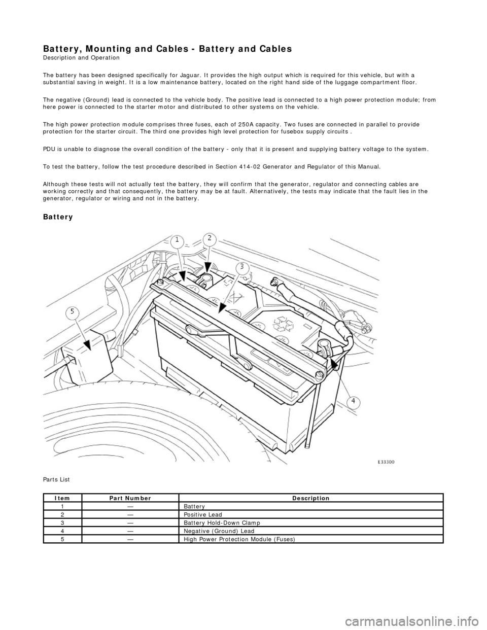
Battery, Mounting and Cables - Battery and Cables Description and Operation
The battery has been designed specifically for Jaguar. It provides the high output which is required for this vehicle, but with a
substantial saving in weight. It is a low maintenance battery, located on the right ha nd side of the luggage compartment floor.
The negative (Ground) lead is connected to the vehicle body. The positive lead is connected to a high power protection module; from
here power is connected to the starter motor an d distributed to other systems on the vehicle.
The high power protection module comprises three fuses, each of 250A capacity. Two fuses are connected in parallel to provide
protection for the starter circuit. Th e third one provides high level protection for fusebox supply circuits .
PDU is unable to diagnose the overall condition of the battery - only that it is present and supplying battery voltage to the system.
To test the battery, follow the test procedure described in Section 414-02 Generator and Regulator of this Manual.
Although these tests will not actually test the battery, they will confirm that the generator, regulator and connecting cables are
working correctly and that conseq uently, the battery may be at fault. Alternatively, the tests may indicate that the fault lies in the
generator, regulator or wiring and not in the battery.
Battery
Parts List
ItemPart NumberDescription
1—Battery
2—Positive Lead
3—Battery Hold-Down Clamp
4—Negative (Ground) Lead
5—High Power Protection Module (Fuses)
Page 1882 of 2490

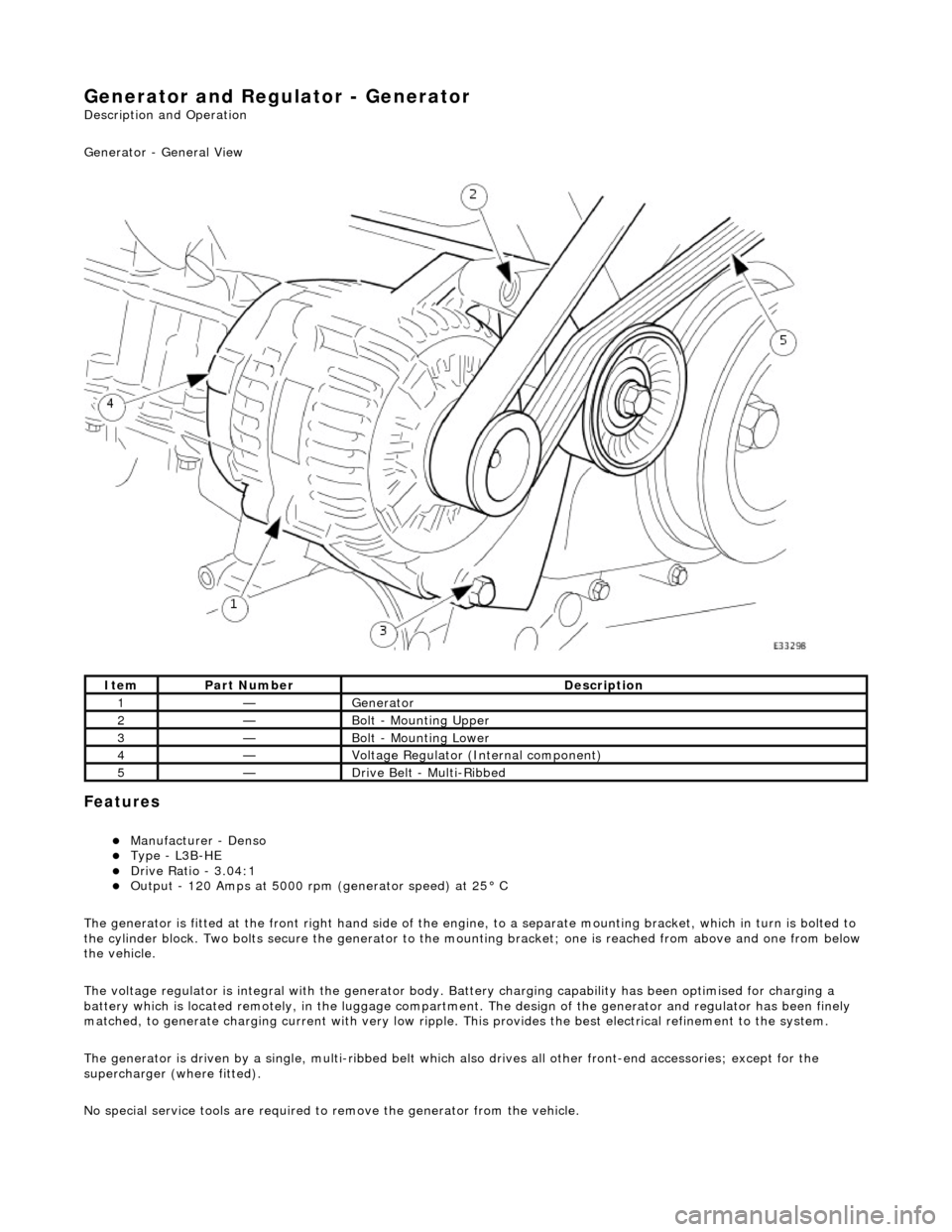
Generator and Regulator - Generator
Description and Operation
Generator - General View
Features
Manufacturer - Denso Type - L3B-HE Drive Ratio - 3.04:1 Output - 120 Amps at 5000 rpm (generator speed) at 25° C
The generator is fitted at the front right hand side of the engine, to a sepa rate mounting bracket, which in turn is bolted to
the cylinder block. Two bolts secure th e generator to the mounting bracket; one is reached from above and one from below
the vehicle.
The voltage regulator is integral with th e generator body. Battery charging capabi lity has been optimised for charging a
battery which is located remotely, in the luggage compartment. The design of the generator and regulator has been finely
matched, to generate charging current with very low ripple. This provides the best electrical refinement to the system.
The generator is driven by a single, multi-ribbed belt which also drives all other front-e nd accessories; except for the
supercharger (where fitted).
No special service tools are required to remove the generator from the vehicle.
ItemPart NumberDescription
1—Generator
2—Bolt - Mounting Upper
3—Bolt - Mounting Lower
4—Voltage Regulator (Internal component)
5—Drive Belt - Multi-Ribbed
Page 1893 of 2490

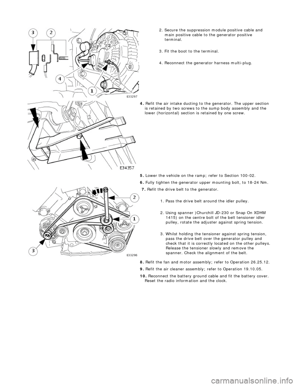
2. Secure the suppression module positive cable and
main positive cable to the generator positive
terminal.
3. Fit the boot to the terminal.
4. Reconnect the generator harness multi-plug.
4. Refit the air intake ducting to the generator. The upper section
is retained by two screws to the sump body assembly and the
lower (horizontal) section is retained by one screw.
5. Lower the vehicle on the ramp ; refer to Section 100-02.
6. Fully tighten the generator upper mounting bolt, to 18-24 Nm.
7. Refit the drive belt to the generator.
1. Pass the drive belt around the idler pulley.
2. Using spanner )Churchill JD-230 or Snap On XDHM 1415) on the centre bolt of the belt tensioner idler
pulley, rotate the adjuster against spring tension.
3. Whilst holding the tensioner against spring tension, pass the drive belt over the generator pulley and
check that it is correctly located on the other pulleys.
Release the tensioner slowly and remove the
spanner. Check the alignment of the belt.
8. Refit the fan and motor assembly ; refer to Operation 26.25.12.
9. Refit the air cleaner assembly; refer to Operation 19.10.05.
10. Reconnect the battery ground cable and fit the battery cover.
Reset the radio inform ation and the clock.
Page 1897 of 2490
2. Fit the lower mounting bolt and nut, tighten to 38-48
Nm.
3. Connect the harness.
1. Secure the main positive cable to the generator positive terminal.
2. Fit the boot to the terminal.
3. Reconnect the generator harness multi-plug.
4. Refit the air intake ducting to the generator. The upper section
is retained by two screws to the sump body assembly and the
lower (horizontal) section is retained by one screw.
5. Lower the vehicle on the ramp ; refer to Section 100-02.
6. Fully tighten the generator upper mounting bolt, to 18-24 Nm.
7. Reposition the superc harger water pump.
1. Reposition the pump to the mounting bracket.
2. Fit the U-bracket to the pump.
3. Fit the two nuts which secure the U-bracket around the pump.
4. Reposition the pump harness multiplug to the retaining bracket.
8. Refit the drive belt to the generator.
1. Pass the drive belt around the idler pulley.
2. Using spanner )Churchill JD-230 or Snap On XDHM
Page 1985 of 2490
Module Communications Network - Front Auxiliary Junction Box
Removal and Installation
Removal
1. Disconnect battery ground cable; refer to 86.15.19.
2. Open bonnet and fit body pa intwork protection sheets.
3. Remove positive supply power cable.
1. Displace cover.
2. Remove nut.
3. Disconnect cable.
4. Remove fuse box fro m mounting panel.
1. Release securing latch, upwards, displace fuse box
outwards and remove from mounting panel.
2. Release securing tangs and remove cover.
5. Remove fuse box.
1. Identify and disconne ct harness connectors.
6. Remove fuses and relays.
Page 1987 of 2490
Module Communications Network - Rear Auxiliary Junction Box
Removal and Installation
Removal
1. Disconnect battery ground cable; refer to 86.15.19.
2. Open bonnet and fit body pa intwork protection sheets.
3. Remove positive supply power cable.
1. Displace cover.
2. Remove nut.
3. Disconnect cable.
4. Remove fuse box fro m mounting panel.
1. Remove nuts.
Reposition fuse box for access to connectors.
5. Remove fuse box.
Identify and disconnect harness connectors.
6. Remove fuses and relay.
Page 2019 of 2490

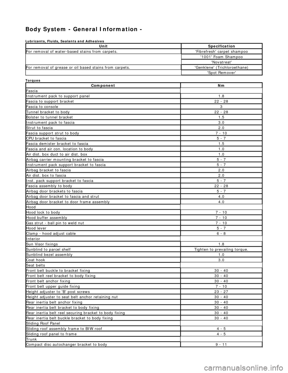
Body System - General Information -
Lubricants, Fluids, Sealants and Adhesives
Torques
UnitSpecification
For removal of water-based stains from carpets.'Fibrefresh' carpet shampoo
'1001' Foam Shampoo
'Novatreat'
For removal of grease or oil based stains from carpets.'Genklene' (Trichloroethane)
'Spot Remover'
ComponentNm
Fascia
Instrument pack to support panel1.8
Fascia to support bracket22 - 28
Fascia to console3
Tunnel bracket to body22 - 28
Bolster to tunnel bracket1.5
Instrument pack to fascia3.0
Strut to fascia2.0
Fascia support strut to body7 - 10
CPU bracket to fascia5 - 7
Fascia demister bracket to fascia1.5
Fascia and air con. location to body1.0
Air dist. box duct to air dist. box1.0
Airbag carrier mounting bracket to fascia5 - 7
Instrument pack suppo rt bracket to fascia5 - 7
Airbag bracket to fascia2.0
Air dist. box to fascia2.0
Inst. pack support bracket to fascia5 - 7
Fascia assembly to body22 - 28
Airbag door brackets to fascia5 - 7
Airbag door bracket to fascia and strut4.0
Airbag door bracket to door frame assembly4.0
Hood
Hood lock to body7 - 10
Hood buffer assembly7 - 10
Gas strut - ball pin to weld nut7 - 10
Hood lever5 - 7
Clamp - hood adjust cable6 - 8
Interior
Sun Visor fixings1.8
Sunblind to parcel shelfTighten to prevailing torque.
Sunblind bezel assembly1.0
Coat hook3.0
Seat belts
Front belt buckle to bracket fixing30 - 40
Front belt reel bracket to body fixing30 - 40
Front belt anchor fixing30 - 40
Front belt upper guide fixing7 - 10
Height adjuster to 'B' post screws23 - 27
Height adjuster to seat belt anchor retaining nut30 - 40
Rear inertia belt anchor fixing30 - 40
Rear inertia belt bracket to body fixing30 - 40
Rear inertia belt reel secu ring bracket to body fixing30 - 40
Rear inertia belt buckle bracket to body fixing30 - 40
Sliding Roof Panel
Sliding roof assembly frame to BIW roof4 - 5
Sliding roof panel to frame4 - 5
Trunk
Compact disc autochanger bracket to body9 - 11
Page 2020 of 2490
Battery clamp to tray7 - 10
Warning triangle lower bracket to trunk lid inner panel1.5
Trunk lock barrel to lid4 - 5
Trunk latch to lid and striker to body7 - 10
Trunk latch motor to bracket7 - 10
Trunk latch motor mounting bracket to lid7-10
Electrical carrier box to body5 - 7
Load floor support block to body9 - 11
Trunk seal retainer to body9 - 11