1998 JAGUAR X308 power steering
[x] Cancel search: power steeringPage 518 of 2490
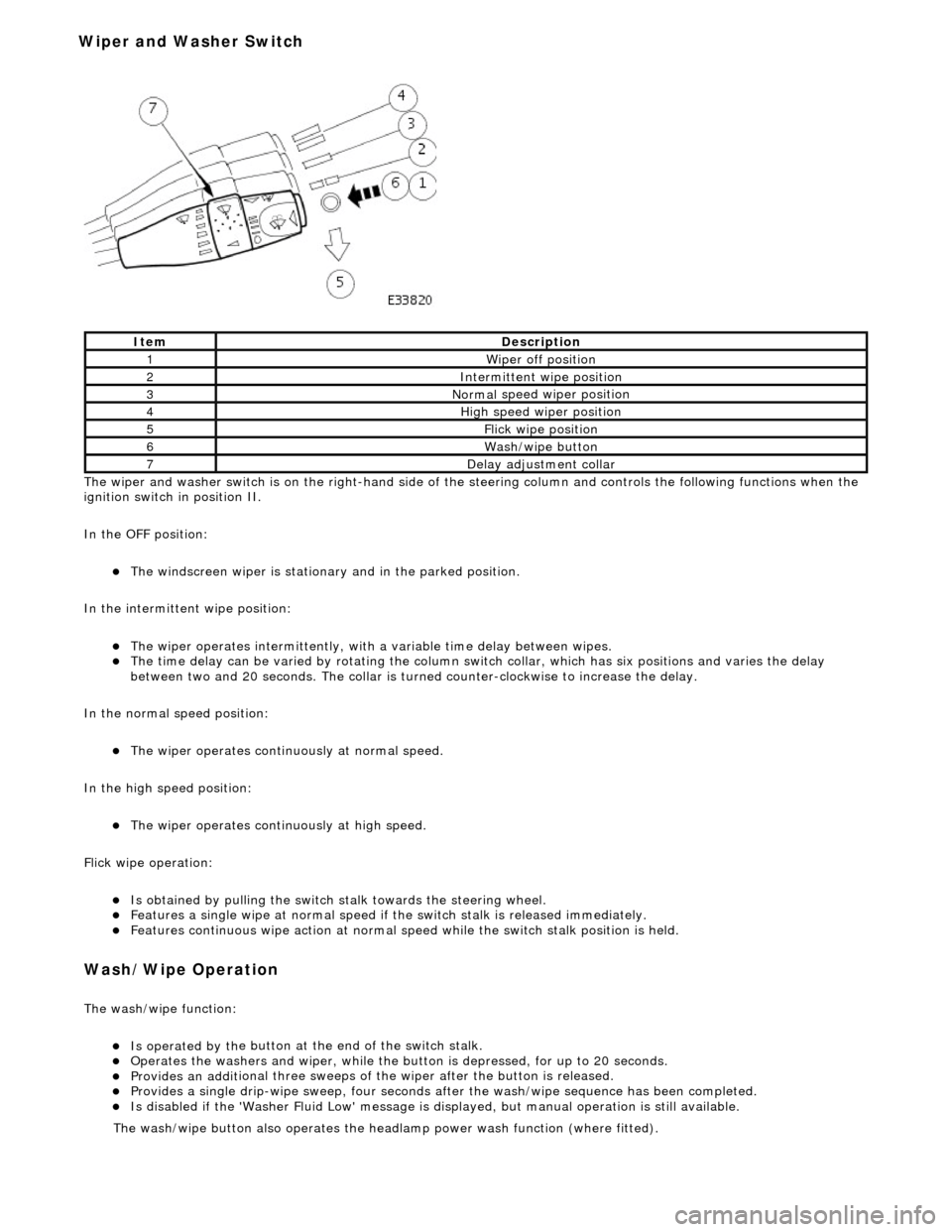
The wiper and washer switch i s
on the righ
t-hand side of the steering column and controls the fo llowing functions when the
ignition switch in position II.
In the OFF position:
The windscreen wiper is stationary and in the parked positio
n.
In the intermittent wipe position:
The wi per ope
rates intermittently, with
a variable time delay between wipes.
The time del
ay can be varied by rotating the column sw
itch collar, which has six positions and varies the delay
between two and 20 seconds. The collar is turned counter-clockwise to increase the delay.
In the normal speed position:
The wiper oper a
tes continuously at normal speed.
In the high speed position:
The wiper ope r
ates continuously at high speed.
Flick wipe operation:
Is obt
ained by pulling the switch
stalk towards the steering wheel.
F
e
atures a single wipe at normal speed if
the switch stalk is released immediately.
Fe
atures continuous wipe action
at normal speed while the swit ch stalk position is held.
Wash/W
ipe Operation
Th
e
wash/wipe function:
Is operat
ed by th
e button at the end of the switch stalk.
Op
erate
s the washers and wiper, while the butt
on is depressed, for up to 20 seconds.
Provides an addit
ional three sweeps of
the wiper after the button is released.
Provid
es a single drip-wipe sweep, four seconds af
ter the wash/wipe sequence has been completed.
Is disabled if the 'Washer Flu
id Low' message is di
splayed, but manual operat ion is still available.
Ite
m
De
scr
iption
1W
i
per off position
2Intermittent
wipe position
3Normal
speed wiper position
4High
speed wiper position
5Flick wipe position
6Wa
sh/wipe button
7D
e
lay adjustment collar
The was
h
/wipe button also operates the head
lamp power wash function (where fitted).
Wiper and Washer Switch
Page 903 of 2490

36. Disconnect the engine oi l pressure transmitter.
37. Remove the filler cap from the power steering reservoir.
38. Disconnect the hoses from the power steering pump.
Position a drain tray under the pump.
1. Release the high pressure hose union nut and drain the fluid.
2. Discard the O-ring seal an d fit blanking plugs to the
pipe and union.
3. Release the feed hose from the pump and fit blanking
plugs to the pipe and union.
Discard the fluid.
39. Release the Oxygen sensor multi-plugs from the mounting
bracket and disconnect the plugs.
40. Remove the four nuts, each side, which secure the downpipe
catalytic converters to the exhaust manifold.
Page 917 of 2490

WARNING: B
EFORE PROCEEDING, IT IS ESSENTIAL THAT
THE WARNING NOTES GIVEN IN SECTION 100-00 (UNDER
THE HEADING 'SAFETY PRECAUTION S') ARE READ AND UNDERSTOOD.
3.
Connect the vacuum hose to the purge valve.
30
.
Connect the fuel feed and return hoses.
R
emove the blanking plugs
from the mating pipes.
1. Connect the hoses at the Quick Fit connectors.
F
it the return hose into the feed hose clip.
31
.
Connect the starter motor power cable.
1. Reposition and connect the power cable to the power stud. Fit the securing nut to the stud.
2. Reposition the protective boot over the starter motor power stud.
3. Connect the harness connector, engine management harness to starter motor. Fit the connector to the
mounting bracket.
R
enew the tie strap which secures the power cable to the
right hand enclosure.
32
.
Connect the generator suppressi on module (where fitted)
harness.
Re
position the harn
ess under the suppression module and
connect the harness connector.
33. Connect the hoses to the power steering pump.
Page 1049 of 2490
Accessory Drive - Accessory Drive
Description an
d Operation
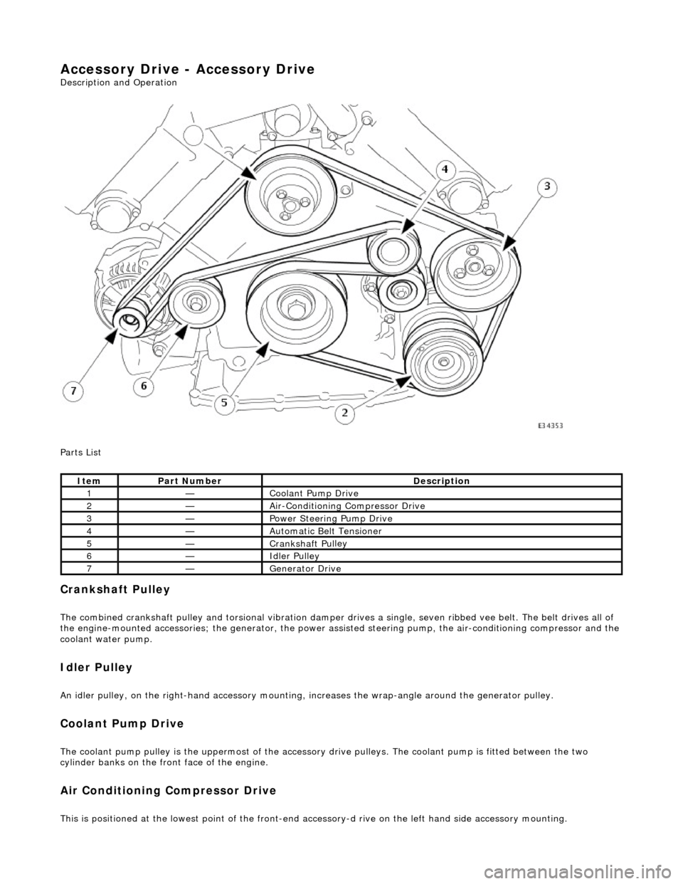
Parts List
Cran
kshaft Pulley
The combined crankshaft
pulley and torsio
nal vibration damper drives a single, seve n ribbed vee belt. The belt drives all of
the engine-mounted accessories; the generator, the power assi sted steering pump, the air-conditioning compressor and the
coolant water pump.
I
dler Pulley
An i
dler pulley, on the right-hand
accessory mounting, increases the wrap-angle around the generator pulley.
Coolant Pump Drive
The coolan
t pump pulley is the
uppermost of the accessory drive pulleys. Th e coolant pump is fitted between the two
cylinder banks on the front face of the engine.
Air Conditioning Compressor Drive
Thi
s is positioned at the lowest poin
t of the front-end accessory-d rive on the left hand side accessory mounting.
It
em
Par
t Number
De
scription
1—Coo
lant Pump Drive
2—Ai
r-Conditioning Compressor Drive
3—Power Steer
ing Pump Drive
4—Au
tomatic Belt Tensioner
5—Crankshaft Pul
ley
6—Idle
r Pulley
7—Generator Dri
ve
Page 1050 of 2490
Power Assisted Steering Pump Drive
The power assisted steering pump pull
ey
is located on the left side, above the air-conditioning compressor.
Generator Dr
ive
The genera
tor is fitted on the
right hand accessory mounting.
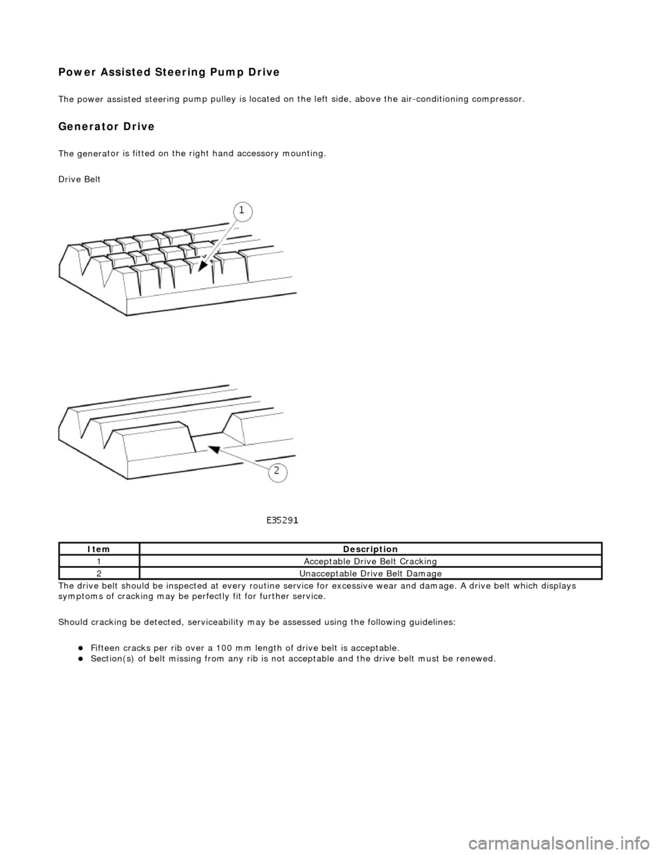
Drive Belt
The drive belt should be inspected at every routine service for excessive wear and damage. A drive belt which displays
symptoms of cracking may be pe rfectly fit for further service.
Should cracking be detected, serviceability ma y be assessed using the following guidelines:
Fi
fteen cracks per rib over a 100 mm le
ngth of drive belt is acceptable.
Sec
tion(s) of belt missing from an
y rib is not acceptable and the drive belt must be renewed.
Ite
m
De
scr
iption
1Ac
c
eptable Drive Belt Cracking
2Unacceptable Drive Belt Damage
Page 1070 of 2490
Starting System - Starter Motor
Remo
val and Installation
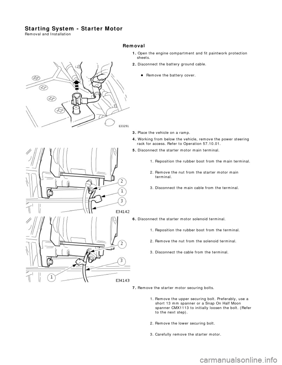
Remov
a
l
1.
Op
en the engine compartment and fit paintwork protection
sheets.
2. Disc
onnect the batt
ery ground cable.
Re
move the battery cover.
3. Place the vehicle on a ramp.
4. Working from below the vehicle, remove the power steering
rack for access. Refer to Operation 57.10.01.
5. Disc
onnect the starter motor main terminal.
1. Reposition the rubber b oot from the main terminal.
2. Remove the nut from the starter motor main terminal.
3. Disconnect the main cable from the terminal.
6. Di
sconnect the starter motor solenoid terminal.
1. Reposition the rubber boot from the terminal.
2. Remove the nut from the solenoid terminal.
3. Disconnect the cable from the terminal.
7. Remove the starter mo tor securing bolts.
1. Remove the upper securing bolt. Preferably, use a short 13 mm spanner or a Snap On Half Moon
spanner CMX1113 to initially loosen the bolt. (Refer
to the next step).
2. Remove the lower securing bolt.
3. Carefully remove the starter motor.
Page 1201 of 2490
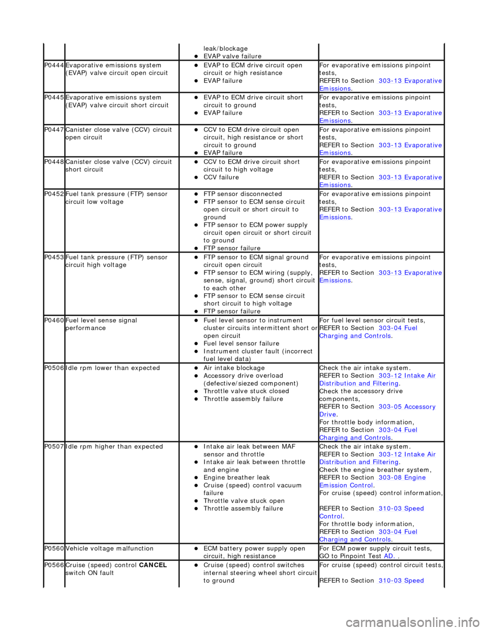
leak
/blockage
EVAP valve failure
P0444Evaporati
ve emissions system
(EVAP) valve circuit open circuit
EVAP t
o ECM drive circuit open
circuit or high resistance
EVAP failu
re
F
or evaporative emissions pinpoint
tests,
REFER to Section 303
-1
3 Evaporative
Emiss
ions
.
P0445Evaporati
ve emissions system
(EVAP) valve circuit short circuit
E
VAP to ECM drive circuit short
circuit to ground
EVAP failu
re
F
or evaporative emissions pinpoint
tests,
REFER to Section 303
-1
3 Evaporative
Emiss
ions
.
P0447Cani
ster close valve (CCV) circuit
open circuit
CCV to ECM
drive circuit open
circuit, high resi stance or short
circuit to ground
EVAP failu
re
F
or evaporative emissions pinpoint
tests,
REFER to Section 303
-1
3 Evaporative
Emiss
ions
.
P0448Cani
ster close valve (CCV) circuit
short circuit
CCV to
ECM drive circuit short
circuit to high voltage
CCV failure
F
or evaporative emissions pinpoint
tests,
REFER to Section 303
-1
3 Evaporative
Emiss
ions
.
P0452F
uel tank pressure (FTP) sensor
circuit low voltage
FTP
sensor disconnected
FTP
sensor to ECM sense circuit
open circuit or short circuit to
ground
FTP sen
sor to ECM power supply
circuit open circuit or short circuit
to ground
F
TP sensor failure
F
or evaporative emissions pinpoint
tests,
REFER to Section 303
-1
3 Evaporative
Emiss
ions
.
P0453F
uel tank pressure (FTP) sensor
circuit high voltage
FTP
sensor to ECM signal ground
circuit open circuit
F
TP sensor to ECM wiring (supply,
sense, signal, ground) short circuit
to each other
FTP
sensor to ECM sense circuit
short circuit to high voltage
F
TP sensor failure
F
or evaporative emissions pinpoint
tests,
REFER to Section 303
-1
3 Evaporative
Emiss
ions
.
P0460Fue
l level sense signal
performance
Fue
l level sensor
to instrument
cluster circuits in termittent short or
open circuit
F
uel level sensor failure
Instrument cluster
faul
t (incorrect
fuel level data)
F
or fuel level sensor
circuit tests,
REFER to Section 303
-04
Fuel
Charging and Con
trols
.
P0506Idl
e rpm lower than expected
Ai
r intake blockage
Acce
ssory drive overload
(defective/siezed component)
Thr
ottle valve stuck closed
Throttl
e assembly failure
Chec
k the air intake system.
REFER to Section 303
-1
2 Intake Air
Distribu
tion and Filtering
.
Check t
he accessory drive
components,
REFER to Section 303
-0
5 Accessory
Dr
ive
.
F
or throttle body information,
REFER to Section 303
-04
Fuel
Charging and Con
trols
.
P0507Idle rpm
higher than expected
Inta
ke air leak between MAF
sensor and throttle
Inta
ke air leak between throttle
and engine
Engine
breather leak
Cruis
e (speed) control vacuum
failure
Thr
ottle valve stuck open
Throttl
e assembly failure
Chec
k the air intake system.
REFER to Section 303
-1
2 Intake Air
Distribu
tion and Filtering
.
Chec
k the engine breather system,
REFER to Section 303
-08
Engine
Emissi
on Control
.
F
or cruise (speed) control information,
REFER to Section 310
-03
Speed
Control.
F
or throttle body information,
REFER to Section 303
-04
Fuel
Charging and Con
trols
.
P0560Vehicle voltage
malfunction
ECM battery
power supply open
circuit, high resistance
F
or ECM power supply circuit tests,
GO to Pinpoint Test AD.
.
P0566Cruise (speed) contr
ol
CANCEL
switch ON fault
Cru
ise (speed) control switches
internal steering wheel short circuit
to ground
For cru
ise (speed) control circuit tests,
REFER to Section 310
-03
Speed
Page 1202 of 2490
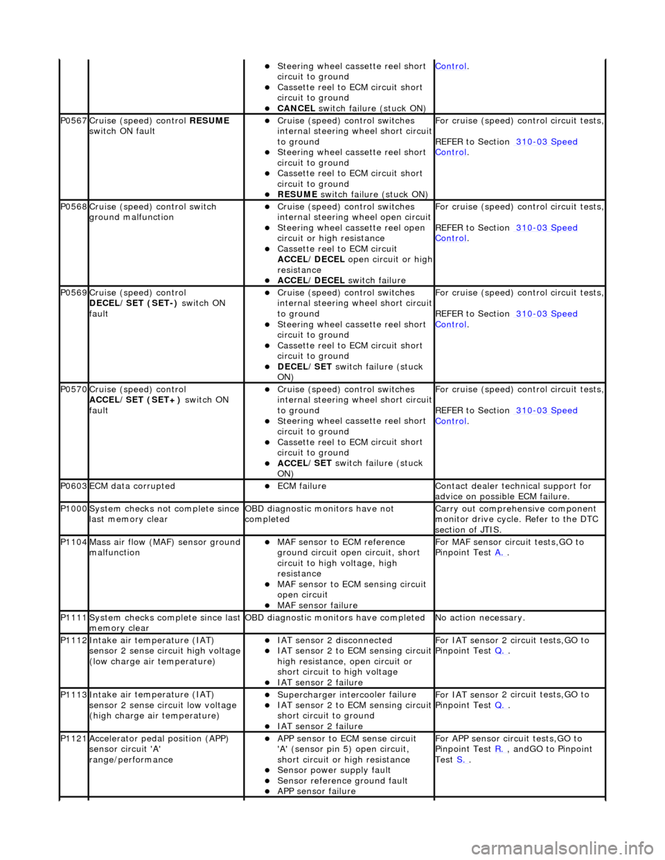
St
eering wheel cassette reel short
circuit to ground
Cassette reel to ECM c
ircuit short
circuit to ground
CANC EL
switch failure (stuck ON)
Control.
P0567Cruise (speed) contr
o
l
RESUME
switch ON fault
Cru i
se (speed) control switches
internal steering wheel short circuit
to ground
S t
eering wheel cassette reel short
circuit to ground
Cassette reel to ECM c
ircuit short
circuit to ground
RESUME s
witch failure (stuck ON)
For cru
i
se (speed) control circuit tests,
REFER to Section 310
-03 Sp
eed
Control.
P0568Cru
i
se (speed) control switch
ground malfunction
Cru i
se (speed) control switches
internal steering wheel open circuit
St
eering wheel cassette reel open
circuit or high resistance
Cassette reel to ECM ci
rcuit
ACCEL/DECEL open circuit or high
resistance
ACC E
L/DECEL
switch failure
For crui
se (speed) control circuit tests,
REFER to Section 310
-03 Sp
eed
Control.
P0569Cruise (speed) contr
o
l
DECEL/SET (SET-) switch ON
fault
Cru i
se (speed) control switches
internal steering wheel short circuit
to ground
S t
eering wheel cassette reel short
circuit to ground
Cassette reel to ECM c
ircuit short
circuit to ground
DECE
L/SET
switch failure (stuck
ON)
For cru i
se (speed) control circuit tests,
REFER to Section 310
-03 Sp
eed
Control.
P0570Cruise (speed) contro
l
ACCEL/SET (SET+) switch ON
fault
Crui
se (speed) control switches
internal steering wheel short circuit
to ground
S t
eering wheel cassette reel short
circuit to ground
Cassette reel to ECM c
ircuit short
circuit to ground
ACC E
L/SET
switch failure (stuck
ON)
For crui
se (speed) control circuit tests,
REFER to Section 310
-03 Sp
eed
Control.
P0603ECM dat
a
corrupted
ECM failu
r
e
Contact deal
er techni
cal support for
advice on possible ECM failure.
P1000 Sy
stem checks not complete since
last memory clear
O B
D diagnostic monitors have not
completed
Carr y out comprehensi
ve component
monitor drive cycle. Refer to the DTC
section of JTIS.
P1104Mass ai r fl
ow (MAF) sensor ground
malfunction
MAF sensor to EC
M reference
ground circuit open circuit, short
circuit to high voltage, high
resistance
MAF s
ensor to ECM sensing circuit
open circuit
MAF sensor fai
lure
For MAF
se
nsor circuit tests,GO to
Pinpoint Test A.
.
P1111Syst
em checks complete since last
memory clear
O B
D diagnostic monitors have completed
N
o
action necessary.
P1112In
t
ake air temperature (IAT)
sensor 2 sense circuit high voltage
(low charge air temperature)
IAT sensor 2 di sconnect
ed
IAT sensor 2
to ECM sensing circuit
high resistance, open circuit or
short circuit to high voltage
IAT se nsor 2 failure
F
or IAT sensor
2 circuit tests,GO to
Pinpoint Test Q.
.
P1113Int
ake air temperature (IAT)
sensor 2 sense circuit low voltage
(high charge air temperature)
Supercharger interco
oler failure
IAT se
nsor 2
to ECM sensing circuit
short circuit to ground
IAT se nsor 2 failure
F
or IAT sensor
2 circuit tests,GO to
Pinpoint Test Q.
.
P1121Accele
rator pedal position (APP)
sensor circuit 'A'
range/performance
A P
P sensor to ECM sense circuit
'A' (sensor pin 5) open circuit,
short circuit or high resistance
Sensor power su pply fault
Sensor r
e
ference ground fault
APP s
e
nsor failure
For APP
sen
sor circuit tests,GO to
Pinpoint Test R.
, andGO to Pinpoint
Test S.
.