Page 2008 of 2490

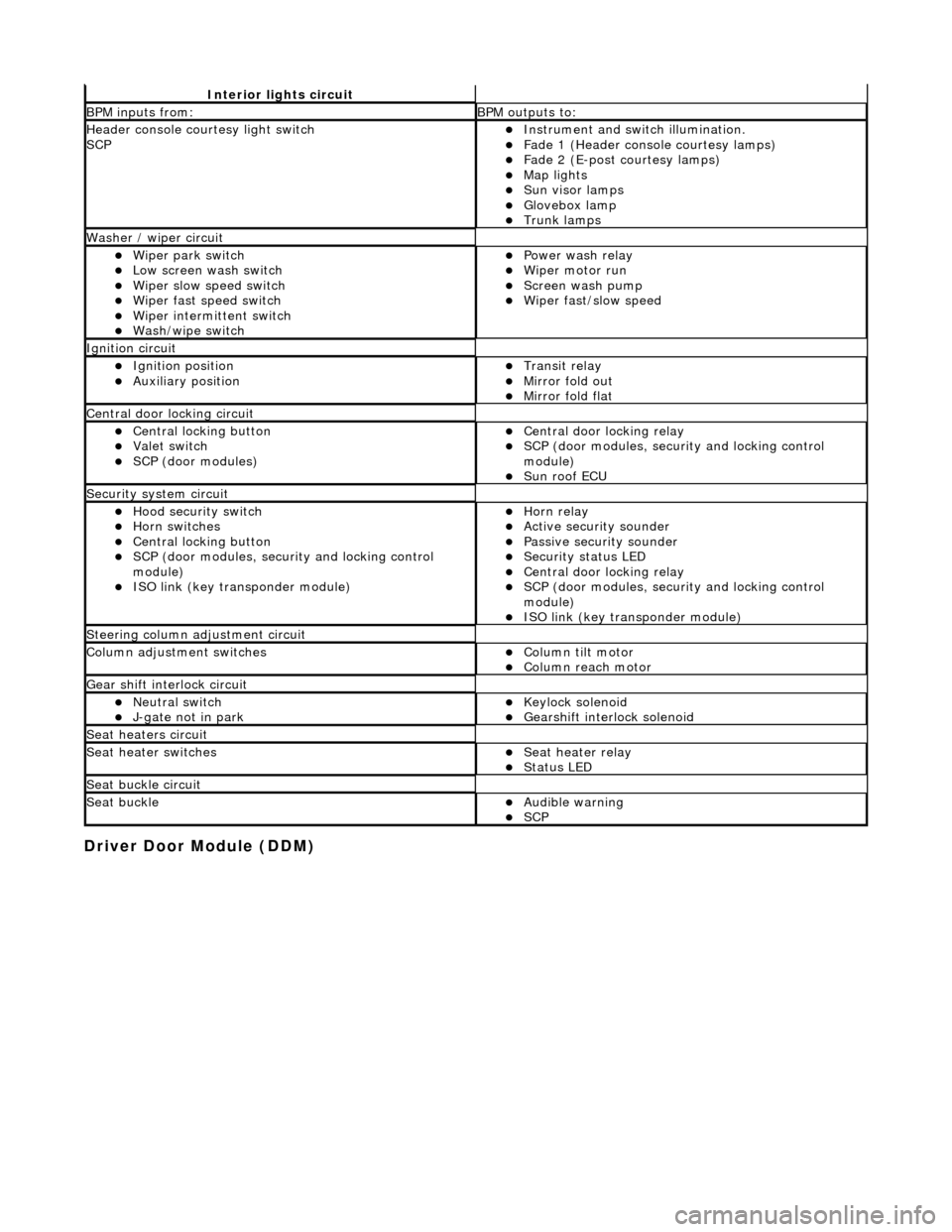
Driver Door Module (DDM)
Interior lights circuit
BPM inputs from: BPM outputs to:
Header console courtesy light switch
SCPInstrument and switch illumination. Fade 1 (Header console courtesy lamps) Fade 2 (E-post courtesy lamps) Map lights Sun visor lamps Glovebox lamp Trunk lamps
Washer / wiper circuit
Wiper park switch Low screen wash switch Wiper slow speed switch Wiper fast speed switch Wiper intermittent switch Wash/wipe switch
Power wash relay Wiper motor run Screen wash pump Wiper fast/slow speed
Ignition circuit
Ignition position Auxiliary position Transit relay Mirror fold out Mirror fold flat
Central door locking circuit
Central locking button Valet switch SCP (door modules)
Central door locking relay SCP (door modules, security and locking control
module)
Sun roof ECU
Security system circuit
Hood security switch Horn switches Central locking button SCP (door modules, security and locking control
module)
ISO link (key transponder module)
Horn relay Active security sounder Passive security sounder Security status LED Central door locking relay SCP (door modules, security and locking control
module)
ISO link (key transponder module)
Steering column adjustment circuit
Column adjustment switchesColumn tilt motor Column reach motor
Gear shift interlock circuit
Neutral switch J-gate not in park Keylock solenoid Gearshift interlock solenoid
Seat heaters circuit
Seat heater switchesSeat heater relay Status LED
Seat buckle circuit
Seat buckleAudible warning SCP
Page 2015 of 2490
Multifunction Electronic Modules - Driver Seat Module (DSM)
Removal and Installation
Removal
1. Power steering column to fully forward position. (Driver side
only)
2. Power seat to fully forward and upward position.
3. WARNING: FOLLOWING DISCONNECTION OF THE
BATTERY A PERIOD OF AT LEAST ONE MINUTE MUST BE
ALLOWED TO ELAPSE BEFORE WORKING ON A FRONT SEAT WITH
A SIDE AIRBAG FITTED.
Remove battery cover and disc onnect ground cable from
battery terminal. Refer to 86.15.19.
4. Slacken and remove seat rear securing bolts.
5. Slacken and remove seat front securing bolts.
6. With assistance and exercising care to avoid tensioning
harness, tilt seat backwa rds and support for access.
7. Slacken and remove module moun ting bracket to seat frame
securing screw.
8. Position module/mounting bracket assembly for access and
Page 2242 of 2490

Instrument Panel and Console - Instrument Panel
Removal and Installation
Removal
1. Turn ignition switch to position II.
2. Motor driver and front passenger seats rearward.
3. Position steering wheel in stra ight ahead position and fully
lower and extend steering column.
4. Turn ignition switch to position O.
5. Remove battery cover and disc onnect ground cable from
battery terminal. Refer to 86.15.19.
6. Remove 'J' gate finish er. Refer to 76.25.24.
7. Remove 'J' gate finisher retain ing panel. Refer to 76.25.26.
8. Remove centre console veneer panel. Refer to 76.47.26.
9. Disconnect and remove radio.
10. Remove centre console switch module. Refer to 86.80.32.
11. Remove centre console. Refer to 76.25.01.
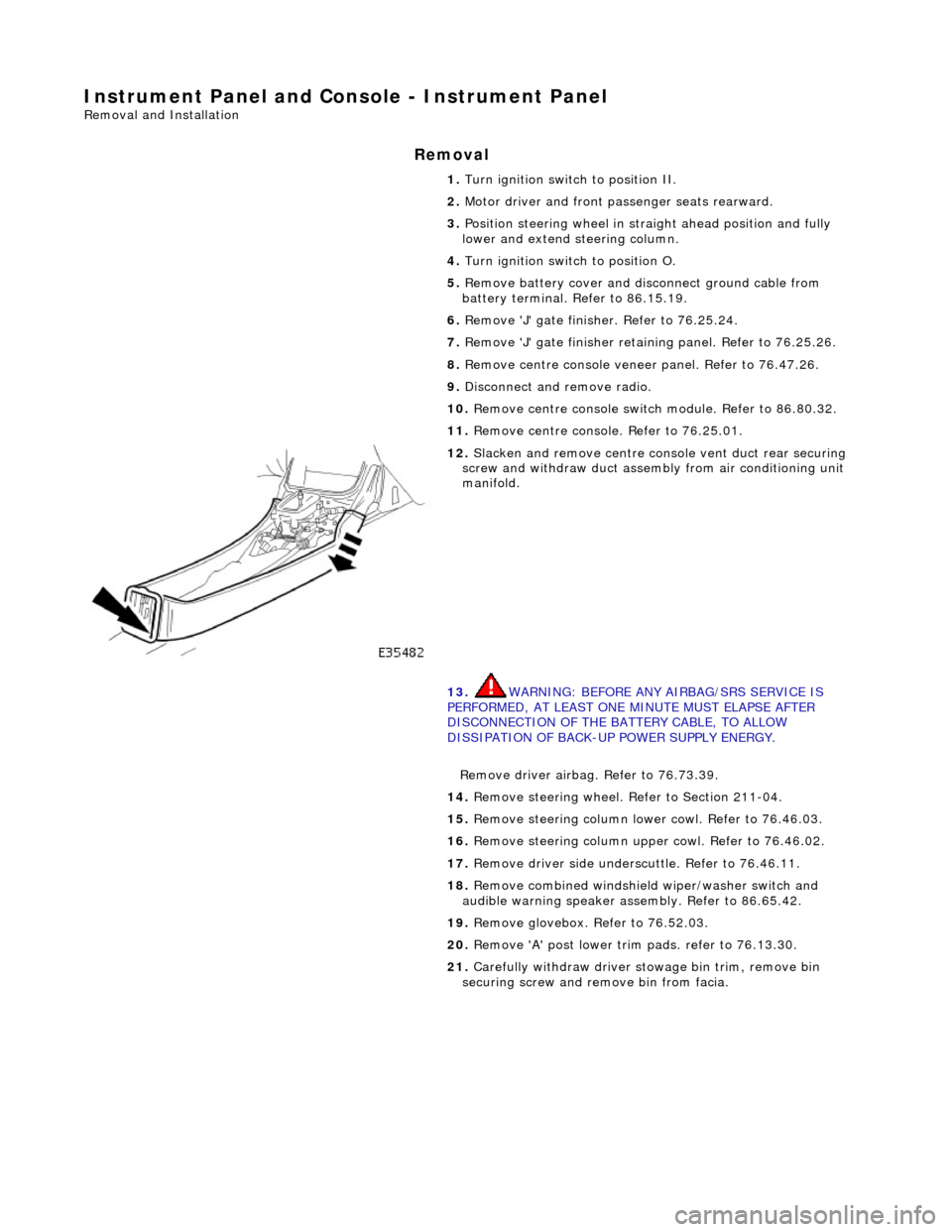
12. Slacken and remove centre cons ole vent duct rear securing
screw and withdraw duct assemb ly from air conditioning unit
manifold.
13. WARNING: BEFORE ANY AIRBAG/SRS SERVICE IS
PERFORMED, AT LEAST ONE MINUTE MUST ELAPSE AFTER
DISCONNECTION OF THE BATTERY CABLE, TO ALLOW
DISSIPATION OF BACK-UP POWER SUPPLY ENERGY.
Remove driver airbag. Refer to 76.73.39.
14. Remove steering wheel. Refer to Section 211-04.
15. Remove steering column lo wer cowl. Refer to 76.46.03.
16. Remove steering column u pper cowl. Refer to 76.46.02.
17. Remove driver side unders cuttle. Refer to 76.46.11.
18. Remove combined windshield wiper/washer switch and
audible warning speaker assembly. Refer to 86.65.42.
19. Remove glovebox. Refer to 76.52.03.
20. Remove 'A' post lower trim pads. refer to 76.13.30.
21. Carefully withdraw driver stowage bin trim, remove bin
securing screw and remove bin from facia.
Page 2423 of 2490
1. Sever and discard tiestraps securing front wheel
speed sensor harness to upper wishbone.
2. Disconnect harness connector from sensor.
Repeat procedure to disconnect opposite side wheel speed
sensor harness.
16. CAUTION: Do not suspend caliper from brake hose as
this will damage the hose.
Remove brake calipers from carriers.
1. Remove caliper spring clip.
2. Remove guide pin dust caps.
3. Slacken and withdraw guide pins.
4. Remove caliper from carrier and tie to suspension mounting bracket.
Repeat procedure to remove opposite side front brake
caliper.
17. Remove filler cap from power steering fluid reservoir.
18. Disconnect steering rack transducer harness front connector.
Release harness connector from body retaining clip.
Disconnect connector.
19. Sever and discard tiestrap secu ring return pipe, harness (RHD
only) and rubber support to steering rack.
Page 2424 of 2490
20. RHD vehicles. Sever and discard tiestrap securing harness to
steering rack.
21. Route harness from behind steering return pipe.
22. Position a drain receptacle below pinion housing.
23. Remove pipe retaining plate secu ring bolt and withdraw plate.
24. Drain power steering fluid.
Disconnect pipes and al low fluid to drain.
Remove and discard 'O'-ring seals from pipe connectors.
Fit blanking plugs to pipe connectors and pinion housing
ports.
25. Remove drain receptacle.
26. Remove pipe support from steering rack.
Release return pipe from support.
Page 2425 of 2490
Remove support from rack.
27. Ensure that steering is in central position.
28. Release lower steering column from pinion shaft.
1. Remove lower steering co lumn securing nut and bolt.
Move column upwards to release it from pinion shaft.
29. Support weight of crossbeam.
Position a jack under crossbeam.
Place a piece of wood between jack and crossbeam.
Raise jack to just support crossbeam.
30. From engine compartment, remove crossbeam front RH
securing bolts.
31. Remove power steering fl uid reservoir for access.
Remove reservoir securing nuts and bolts.
Position reservoir for access.
Page 2433 of 2490
17. From engine compartment, install crossbeam front LH bolts
and tighten to 22-28Nm..
18. Install power steering fluid reservoir.
Position reservoir on mounting bracket.
Install reservoir securi ng nuts and bolts.
19. From engine compartment, tighten crossbeam front RH bolts
to 22-28Nm.
20. Install shock absorber on lower wishbone.
Lift lower wishbone to align shock absorber lower
mounting.
Install bolt and nut and ti ghten nut to 43-57Nm.
Page 2435 of 2490
26. Install power steering pi pes on pinion housing.
Remove blanks and install new 'O'-ring seals in pipe
connectors.
Apply power steering fluid to 'O' ring seals.
Remove blanking plugs from pinion housing ports.
Position pipes on pinion ports and seat 'O' rings.
27. Secure pipes to pinion housing.
Ensure pipes and retaining pl ate are correctly seated.
Install bolt and tighten to 9-12Nm.
28. Secure return pipe on steering rack.
1. Position pipe rubber support on steering rack.
2. Position pipe on support .
3. RHD vehicles. Position harness on pipe support rubber.
4. Secure pipe and harness to support with new tiestrap.
29. RHD vehicles. Using new tiestrap, secure harness to steering
rack.