Page 1745 of 2490

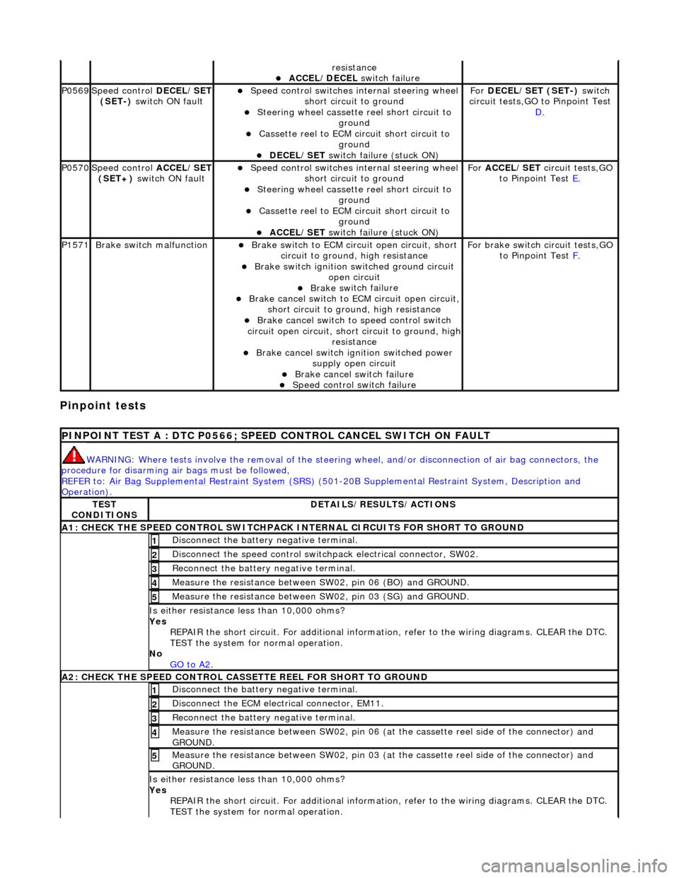
Pinpoint test
s
re
sistance
ACCEL/DECEL
swi
tch failure
P0569Speed
control
DECEL/SET
(SET-) switch ON fault
Speed
control switches internal steering wheel
short circuit to ground
S
teering wheel cassette
reel short circuit to
ground
Cassette reel
to ECM ci
rcuit short circuit to
ground
DEC
EL/SET
switch failure (stuck ON)
Fo
r
DECEL/SET (SET-) switch
circuit tests,GO to Pinpoint Test D.
P0570Speed
control
ACCEL/SET
(SET+) switch ON fault
Speed
control switches internal steering wheel
short circuit to ground
S
teering wheel cassette
reel short circuit to
ground
Cassette reel
to ECM ci
rcuit short circuit to
ground
ACC
EL/SET
switch failure (stuck ON)
Fo
r
ACCEL/SET circuit tests,GO
to Pinpoint Test E.
P1571Brake sw
itch malfunction
Brake sw
itch to ECM circuit open circuit, short
circuit to ground, high resistance
Brake sw
itch ignition switched ground circuit
open circuit
Brake sw
itch failure
Brake ca
ncel switch to
ECM circuit open circuit,
short circuit to ground, high resistance
Brake ca
ncel switch to speed control switch
circuit open circuit, shor t circuit to ground, high
resistance
Brake ca
ncel switch ignition switched power
supply open circuit
Brake ca
ncel switch failure
Spe
ed control switch failure
For brake swi
tch circuit tests,GO
to Pinpoint Test F.
P
INPOINT TEST A : DTC P0566; SPEED
CONTROL CANCEL SWITCH ON FAULT
WAR
NING: Where tests involve the removal of the steering
wheel, and/or disconnection of air bag connectors, the
procedure for disarming air bags must be followed,
REFER to: Air Bag Supplemental Re straint System (SRS)
(501-20B Supplemental Restra
int System, Description and
Operation).
TE
ST
CONDITIONS
D
ETAILS/RESULTS/ACTIONS
A1: CHECK
THE SPEED CONTROL SWITCHPACK IN
TERNAL CIRCUITS FOR SHORT TO GROUND
Di
sconnect the battery negative terminal.
1
Di
sconnect the speed control switch
pack electrical connector, SW02.
2
R
econnect the battery negative terminal.
3
Meas
ure the resistance between SW
02, pin 06 (BO) and GROUND.
4
Meas
ure the resistance between SW
02, pin 03 (SG) and GROUND.
5
Is either resi
stance
less than 10,000 ohms?
Yes REPAIR the short circuit. For addi tional information, refer to the wiring diagrams. CLEAR the DTC.
TEST the system for normal operation.
No GO to A2
.
A2: CHECK
THE SPEED CONTROL CASSE
TTE REEL FOR SHORT TO GROUND
Di
sconnect the battery negative terminal.
1
D
isconnect the ECM electrical connector, EM11.
2
R
econnect the battery negative terminal.
3
M
easure the resistance between SW02, pin 06 (at the cassette reel side of the connector) and
GROUND.
4
M
easure the resistance between SW02, pin 03 (at the cassette reel side of the connector) and
GROUND.
5
Is either resi
stance
less than 10,000 ohms?
Yes REPAIR the short circuit. For addi tional information, refer to the wiring diagrams. CLEAR the DTC.
TEST the system for normal operation.
Page 1804 of 2490
Air Conditioning - Air Conditioning (A/C) Compressor
Removal and Installation
Removal
1. Disconnect battery ground cable (IMPORTANT, see SRO
86.15.19 for further information).
2. Recover refrigerant from air co nditioning system; refer to
82.30.30.
3. Remove supercharger drive belt (where fitted); refer to
18.50.08.
4. Remove front end accessory dr ive belt; refer to 12.10.40 or
(SC) 12.10.40.
5. NOTE: A commercially availa ble brake pipe clamp is
recommended. Do not over tighten.
Clamp power steering reservoir to pump feed hose.
6. Raise vehicle for access
7. NOTE: Position drain tin to collect the fluid when union nut is
released.
Disconnect steering rack hose from pump. 1. Release union nut.
2. Discard O-ring.
3. Install suitable blanking plugs.
8. Disconnect clutch harness connector from compressor.
1. Disconnect connector.
9. Disconnect lines from compressor.
Discard O-rings.
Install suitable blanking plugs.
Page 1806 of 2490
3. Install lines to compressor.
Install new O-ring seal and lubricate with clean
compressor oil.
4. Connect clutch harness connector to compressor.
1. Connect clutch connector.
5. Connect power steering hose to pump.
1. Remove blanking plugs.
2. Install new O-ring seal and lubricate with clean
compressor oil.
3. Tighten union nut.
6. Lower ramp.
7. Unclamp power steering rese rvoir to pump feed hose.
Page 1854 of 2490
Instrument Cluster - Instrument Cluster
Description and Operation
ItemDescription
1Variable Power Steering
2Coolant Level
3Fuel Level
4Oil Pressure
5Lamp Dimmer
6Driver's Switchpack
7Generator (Charge Warning Lamp)
8Catalyst Overheat
9Instrument Cluster
10Climate Control (Signal to Module)
11ICE Head Unit
Page 1904 of 2490
Audio Unit - Audio System
Description and Operation
The choice of two entertainment system s is available; base or premium.
The base system comprises a radio cassette player with in tegral message display and "Phone Ready" controls for an
accessory telephone; door speakers and tweeters.
The premium system has the following additional components: power amplifier, CD autochanger, sub-woofer and 'A' post
tweeters fitted instead of front door tweeters.
Both systems can be operated remotely by use of switches loca ted on the steering wheel and have an electrically operated
aerial.
Telephone controls incorporated in the ra dio cassette unit facilitate inclusion of the GSM hands free telephone system
available as optional equipment.
After diagnostic or repair operations, refer to the Sound System Handbook for setting-up procedures and operation.
Page 1973 of 2490
Module Communications Network - Communications Network
Description and Operation
Fuse Boxes and Relays (LH Steering)
Parts List
There are six fuse box assemblies per vehicle, five of which have conventional, replaceable fuses. The High Power Protection
Module does not have conventional fuses, it comprises three 250 Amp fusible links to protect the starting circuit (two
connected in parallel) and the battery positive supply to the other fuse boxes.
Wiring Harnesses
ItemPart NumberDescription
1—Engine and Transmission Cont rol Module Compartment Relays (RH Steering opposite)
2—Front Firewall Relays
3—Front Seat Relays - Right Hand Side
4—Heelboard - Right Hand Side
5—High Power Protection Module
6—Trunk Fuse Box
7—Heelboard - Left Hand Side
8—Front Seat Relays - Left Hand Side
9—Engine Management Fuse Box
10—Engine Compartment Fuse Box
11—Engine Compartment Front Relays
Page 1975 of 2490

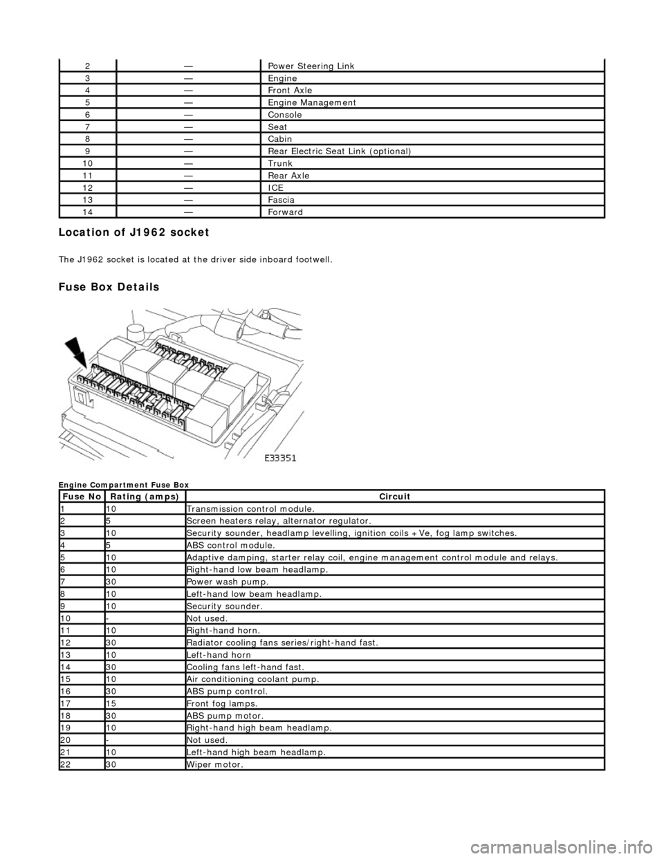
Location of J1962 socket
The J1962 socket is located at the driver side inboard footwell.
Fuse Box Details
Engine Compartment Fuse Box
2—Power Steering Link
3—Engine
4—Front Axle
5—Engine Management
6—Console
7—Seat
8—Cabin
9—Rear Electric Seat Link (optional)
10—Trunk
11—Rear Axle
12—ICE
13—Fascia
14—Forward
Fuse NoRating (amps)Circuit
110Transmission control module.
25Screen heaters relay, alternator regulator.
310Security sounder, headlamp levelling, ignition coils +Ve, fog lamp switches.
45ABS control module.
510Adaptive damping, starter relay coil, engine management control module and relays.
610Right-hand low beam headlamp.
730Power wash pump.
810Left-hand low beam headlamp.
910Security sounder.
10-Not used.
1110Right-hand horn.
1230Radiator cooling fans series/right-hand fast.
1310Left-hand horn
1430Cooling fans left-hand fast.
1510Air conditioning coolant pump.
1630ABS pump control.
1715Front fog lamps.
1830ABS pump motor.
1910Right-hand high beam headlamp.
20-Not used.
2110Left-hand high beam headlamp.
2230Wiper motor.
Page 1977 of 2490

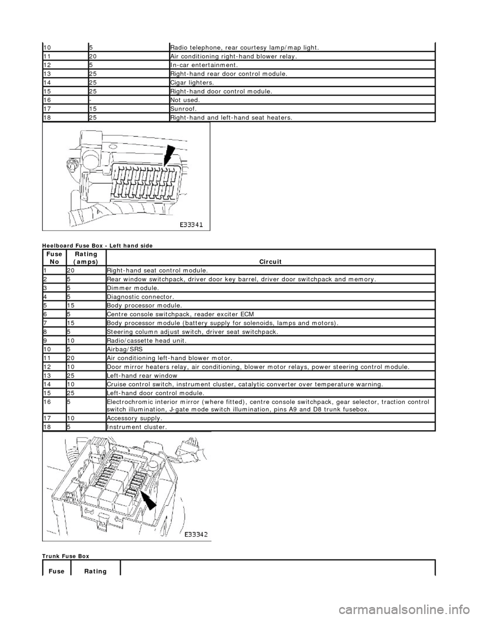
Heelboard Fuse Box - Left hand side
Trunk Fuse Box
105Radio telephone, rear courtesy lamp/map light.
1120Air conditioning right-hand blower relay.
125In-car entertainment.
1325Right-hand rear door control module.
1425Cigar lighters.
1525Right-hand door control module.
16-Not used.
1715Sunroof.
1825Right-hand and left-hand seat heaters.
Fuse NoRating
(amps)Circuit
120Right-hand seat control module.
25Rear window switchpack, driver door key ba rrel, driver door switchpack and memory.
35Dimmer module.
45Diagnostic connector.
515Body processor module.
65Centre console switchpack, reader exciter ECM
715Body processor module (battery supply for solenoids, lamps and motors).
85Steering column adjust switch, driver seat switchpack.
910Radio/cassette head unit.
105Airbag/SRS
1120Air conditioning left-hand blower motor.
1210Door mirror heaters relay, air conditioning, blow er motor relays, power steering control module.
1325Left-hand rear window
1410Cruise control switch, instrument cluster, catalytic converter over temperature warning.
1525Left-hand door control module.
165Electrochromic interior mirror (where fitted), centre console switchpack, gear selector, traction control
switch illumination, J-gate mode switch illumination, pins A9 and D8 trunk fusebox.
1710Accessory supply.
185Instrument cluster.
Fuse Rating