Page 897 of 2490
• WARNINGS:
4. Remove the engine compartment cover (bonnet).
1. Apply masking tape to th e front edge of the engine
compartment cover to protect the paintwork during
removal and storage.
2. With assistance, support the cover and release the
gas struts.
5. With assistance, release the six bolts which retain the cover
(bonnet) and lift the cover clear.
Disconnect the ground cable from the left hand hinge.
6. Remove the engine covers
7. Drain the cooling system. Refer to Operation 26.10.01.
Conserve as much of the coolant as possible to refill the
system.
8. Depressurise the air conditioni ng system. Refer to Operation
82.30.30 and note all Wa rnings and Cautions.
Page 923 of 2490

be 'hun
g up' within the engine because it is not up to operating
temperature.
Should the oil level subsequently be topped-up, the level could
become too high, causing oil burning.
Typically, 0.875L is hung up.
Refill the engine with the correct specification engine oil.
58. Refill the automatic transmission. Refer to Section 307-01A,
Operation 44.24. 02.
59. Refill and bleed the power stee ring system. Refer to Section
211-02 General Procedures.
60. Repressurise the air conditioni ng system. Refer to Operation
82.30.30 and note all Wa rnings and Cautions.
61
.
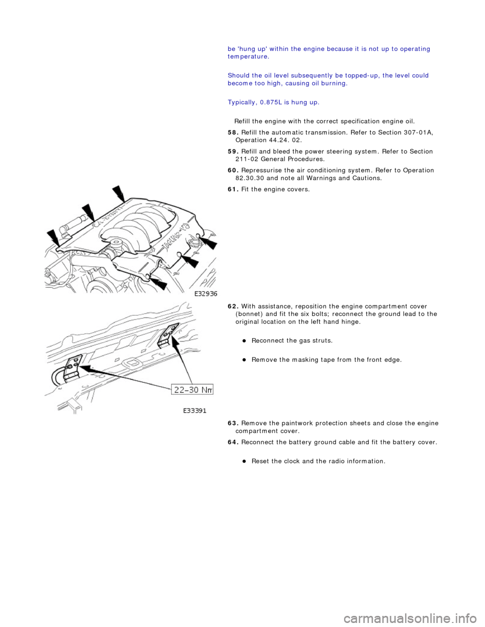
Fit the engine covers.
62
.
With assistance, reposition the engine compartment cover
(bonnet) and fit the si x bolts; reconnect the ground lead to the
original location on the left hand hinge.
Re
connect the gas struts.
R
emove the masking tape from the front edge.
63. Remove the paintwork protection sheets and close the engine
compartment cover.
64. Reconnect the battery ground cable and fit the battery cover.
Re
set the clock and the radio information.
Page 925 of 2490

T
he cooling system for the supercharged engine is very similar
to the normally aspirated engine, but with the addition of a
water cooled, intake air charge cooling system. This comprises a radiator, an electrically operated water pump and two
charge air cooler assemblies (heat exchangers) - one for each bank. The system works independently, but is connected to the
main cooling system at the bottom hose to allow for therma l expansion and to help to prevent unwanted circulation.
The condenser for the air conditioning system fits between th e coolant main radiator and the charge air cooling system
radiator.
Cylinder Block Heater, Drain Location
ItemDe
scription
1Rad
iator - Intake Air Coolant
2Ele
ctrically Operated Coolant Pump
3Top Hose
4Charge Air Coo
lers -
Intake Air Cooling
5Fi
lling Point for Intake Air Cooling
6N
on-Return Valves - Heater
7Ele
ctrically Operated Coolant Pump
8Hea
ter Matrix
9Wate
r Valve - Heater Control
10EGR V
alve (when fitted)
11Thr
ottle Body
12Coolan
t Recovery Bottle
13H
eader/Expansion Tank
14Eng
ine Coolant Pump
15The
rmostat Housing
16Bottom
Hose
17Air Bleed
Pipes
18Rad
iator - Main Cooling System
Page 929 of 2490
The cooling
pack incorporates the radiator a
ssembly with integral transmission oil cool er (located in the radiator outlet tank),
an air conditioning condenser, and the cooling fans and cowl assembly.
The cooling pack on supercharged vehicles is the same as described above, but with the addition of a charge air cooler
coolant radiator located in front of the condenser.
Radiator Mounti
ng/Retention
T
he radiator is mounted on four rubber mounts, one on each
end of the upper and lower horizontal face. The two lower
mountings are supported on two isolated brackets mounted on the body; the lower cradle assembly has subsequently been
deleted.
A closing panel made from polypropylene, which retains the radiat or assembly, fits over the top of the radiator and is bolted
to the vehicle top panel.
Coolant Hoses - Engine
Page 930 of 2490

Whe r
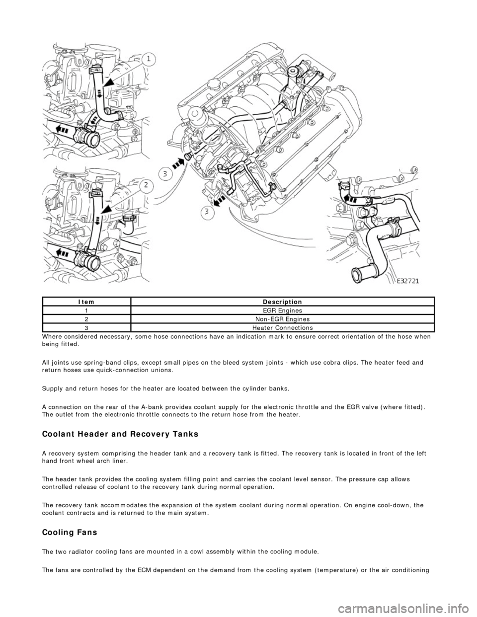
e considered necessary, some hose conn
ections have an indication mark to ensure correct orientation of the hose when
being fitted.
All joints use spring-band clips, except small pipes on the bleed system joints - which use cobra clips. The heater feed and
return hoses use quick-connection unions.
Supply and return hoses for the heater are located between the cylinder banks.
A connection on the rear of the A-bank provides coolant supply for the electronic throttle and the EGR valve (where fitted).
The outlet from the electronic throttle connects to the return hose from the heater.
Cool
ant Header and Recovery Tanks
A recovery system comp
rising the header tank
and a recovery tank is fitted. The recove ry tank is located in front of the left
hand front wheel arch liner.
The header tank provides the cooling system filling point and carries the coolant level sensor. The pressure cap allows
controlled release of coolant to the re covery tank during normal operation.
The recovery tank accommodates the expansion of the system coolant during normal operation. On engine cool-down, the
coolant contracts and is returned to the main system.
Coo lin
g Fans
The two
rad
iator cooling fans are mounted in
a cowl assembly within the cooling module.
The fans are controlled by the ECM dependent on the demand fr om the cooling system (temperature) or the air conditioning
ItemDescrip
tion
1EGR
E
ngines
2Non
-
EGR Engines
3Hea
ter Connections
Page 939 of 2490
Pinpoint test
B: P0117
I
gnition switch to position 0
1
Di
sconnect EM010
Inside E
CM housing
2
Meas
ure the resistance between the ECM connector
EM010/020 and the ECT connector PI004/001.
3
I
s the resistance < 0.5 OHM?
Yes GO to A7
No Inspect harness / connector EM010/020, PI004/001,
PI001/006 and splices EMS02 / PIS01 for corrosion,
damage, bent or pushed back pins. Repair as necessary
and reconnect all connectors.
Test the system for normal operation.
A7
: END
Perform
appropriate service drive cycle and check for the
presence of DTC.
1
Has
the fault code cleared?
Yes STOP
No Contact Jaguar Service
P
INPOINT TEST B : P0117
T
EST CONDITIONS
D
ETAILS/RESULTS/ACTIONS
B1
: RETRIEVE DTCS
•
NOTE: Battery and or ECM disconnection prior to scanning wi
ll erase all data, ensure that the correct DTC is present.
Page 944 of 2490
Pinpoint test C: P0118
I
g
nition switch to position 0
1
Di
sc
onnect EM011
Inside E
C
M housing
2
I
g
nition switch to position II
3
Measure the
voltage betwee n pin
s 9 and 12 of the
connector.
4
Is th e volt
age > 1 V?
Yes Inspect harness / connector EM011/009, PI004/002,
PI001/005 and splices EMS02 / PIS01 for corrosion,
damage, bent or pushed back pins. Repair as required and
reconnect all connectors. Te st the system for normal
operation.
No GO to B7
B7: EN
D
Perform
a
ppropriate service drive cycle and check for the
presence of DTC.
1
Has th
e fault code cleared?
Yes STOP
No Contact Jaguar Service
PINPOINT TES
T C : P0118
T
E
ST CONDITIONS
D
E
TAILS/RESULTS/ACTIONS
C1
: RETRIEVE DTC
S
•
NOTE
: Battery and or ECM disconnection prior to scanning wi
ll erase all data, ensure that the correct DTC is present.
Page 946 of 2490
Pinpoint test D
: P1474
I
g
nition switch to position 0
1
Di
sc
onnect EM011
Inside E
C
M housing
2
Meas
ure t
he resistance betw
een pins 9 and 12 of the
connector.
3
Re si
stance < 0.5 OHM?
Yes Inspect harness / connector EM011/0012, PI004/001,
PI001/006 and splices EMS02 / PIS01 for corrosion,
damage, bent or pushed back pins. Repair as required and
reconnect all connectors. Te st the system for normal
operation.
No GO to C4
C4: END
Perform a
ppropriate service drive cycle and check for the
presence of DTC.
1
Has th
e fault code cleared?
Yes STOP
No Contact Jaguar Service
PINPOINT TES
T D : P1474
T
E
ST CONDITIONS
D
E
TAILS/RESULTS/ACTIONS
D1
:
RETRIEVE DTCS
•
NOTE
: Battery and or ECM disconnection prior to scanning wi
ll erase all data, ensure that the correct DTC is present.