1998 JAGUAR X308 air outlet
[x] Cancel search: air outletPage 1150 of 2490
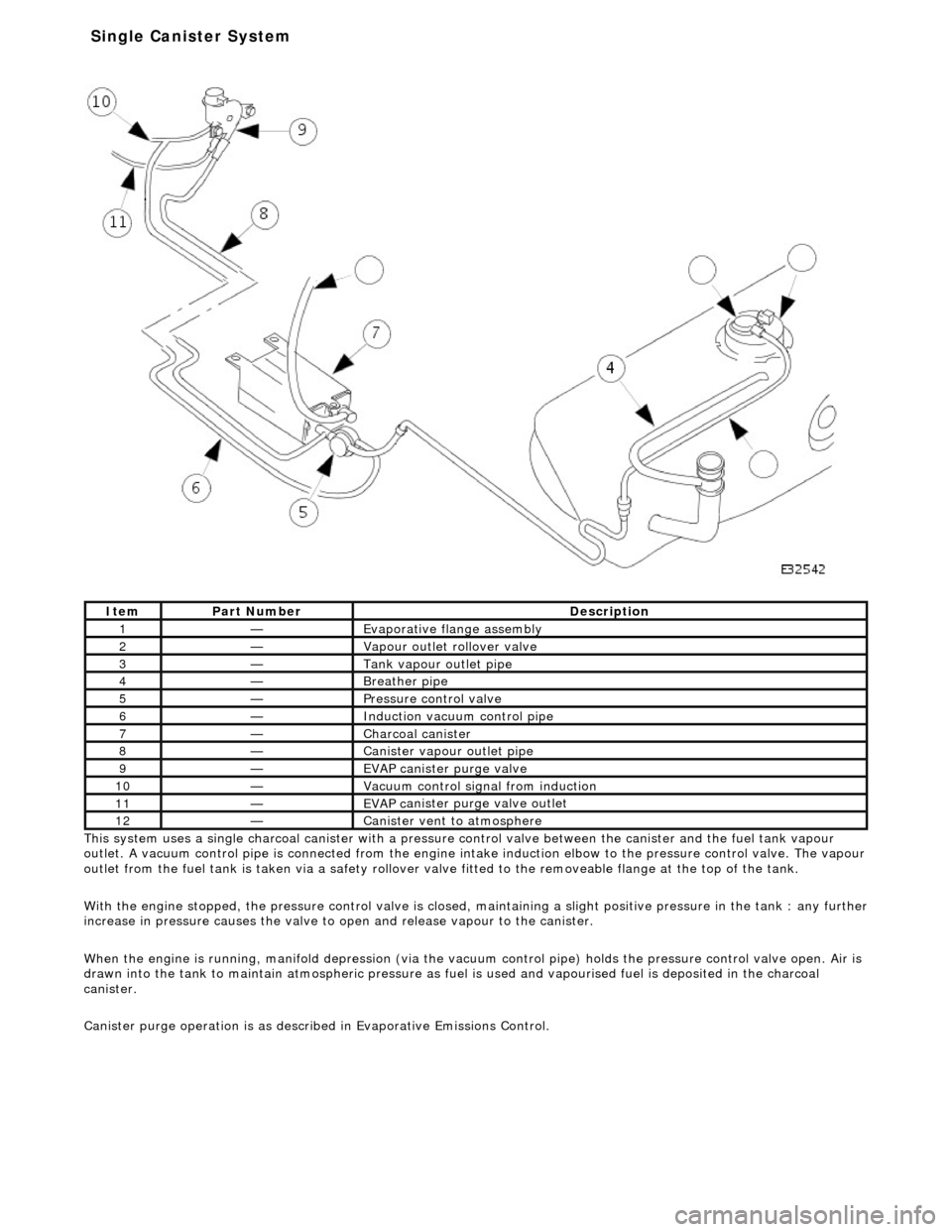
Thi s
system uses a single charcoal canister with a pressure
control valve between the canister and the fuel tank vapour
outlet. A vacuum control pipe is connecte d from the engine intake induction elbow to the pressure control valve. The vapour
outlet from the fuel tank is taken via a safety rollover valve fitted to the re moveable flange at the top of the tank.
With the engine stopped, the pressure control valve is closed, maintaining a slight positive pre ssure in the tank : any further
increase in pressure causes the valve to open and release vapour to the canister.
When the engine is running, manifold depr ession (via the vacuum control pipe) holds the pressure control valve open. Air is
drawn into the tank to maintain atmospheric pressure as fuel is used and vapourised fuel is deposited in the charcoal
canister.
Canister purge operation is as described in Evaporative Emissions Control.
It e
m
Par
t
Number
De
scr
iption
1—Evaporative flan
ge assembly
2—Vapour outlet rol
lover valve
3—Tank vapour outlet pipe
4—Breather
pipe
5—Pressure control valve
6—Induct
ion vacuum control pipe
7—Charcoal can
i
ster
8—Canister vapour outlet pipe
9—EVAP canister purge v
a
lve
10—Vacuu
m
control sign
al from induction
11—EVAP ca
nister purge valve outlet
12—Canist
er vent
to atmosphere
Single Ca
nister System
Page 1162 of 2490
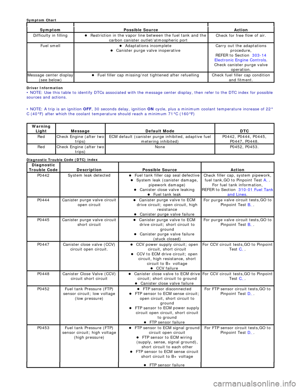
Driver Info
rmation
•
NOTE: Use this table to identify DTCs associated with the me
ssage center display, then refer to the DTC index for possible
sources and actions.
• NOTE: A trip is an ignition OFF, 30 seconds delay, ignition ON cycle, plus a minimum coolant temperature increase of 22°
C (40°F) after which the coolant temperat ure should reach a minimum 71°C (160°F)
Diagnostic Trouble C
ode (DTC) index
Sy
m
ptom
Possib
l
e Source
Acti
o
n
D
i
fficulty in filling
R
e
striction in the vapor line between the fuel tank and the
carbon canister outlet/atmospheric port
Check f or free f
low of air.
F
u
el smell
Adaptat
i
ons incomplete
Cani
st
er purge valve inoperative
Carry
o
ut the adaptations
procedure,
REFER to Section 303
-14 Ele c
tronic Engine Controls
.
Chec k cani
ster purge valve
operation.
M e
ssage center display
(see below)
Fue l
filler cap missing/not
tightened after refuelling
Check fu
el filler cap condition
and fitment.
Warning Li
ght
Mess
age Defaul
t Mode
DT
C
RedCheck Engine (after two
trip
s)
ECM de
fa
ult (canister purge inhibited, adaptive fuel
metering inhibited)
P0442,
P0444, P0445,
P0447, P0448.
Re dCheck Engine (after two
trip
s)
No
neP04 52,
P0453.
Di
agno
stic
Trouble Code
De scr
iption
Possib
l
e Source
Acti
o
n
P0442Sy
st
em leak detected
F
u
el tank filler cap seal defective
Sy
ste
m leak (c
anister damage,
pipework damage)
Cani st
er close valve leaking
F
u
el tank leak
Chec
k fi
ller cap,
system pipework,
fuel tank,GO to Pinpoint Test A.
.
F o
r fuel tank information,
REFER to Section 310
-01 Fu
el Tank
and Lines.
P0444Canist
er purge valve circuit
open circuit
Cani st
er purge valve to ECM
drive circuit; open circuit, high
resistance
Cani st
er purge valve failure
F
or purge
valve circuit tests,GO to
Pinpoint Test B.
.
P0445Canist
er purge valve circuit
short circuit
Cani st
er purge valve to ECM
drive circuit; short circuit to ground
Canist
er purge valve failure
(stuck closed)
F or purge
valve circuit tests,GO to
Pinpoint Test B.
.
P0447Canist
er close valve (CCV)
circuit open circuit.
CCV power su pply ci
rcuit; open
circuit, short circuit
CCV to ECM drive circuit;
open
circuit, high resistance, short circuit to B+ voltage
CCV failure
Fo
r CCV circuit tests,GO to Pinpoint
Test C.
.
P0448Canist
er Close Valve (CCV)
circuit short circuit
Cani st
er close valve to ECM drive
circuit; short circuit to ground
Cani st
er close valve failure
F
o
r CCV circuit tests,GO to Pinpoint
Test C.
.
P0452 Fu
el tank Pressure (FTP)
sensor circuit; low voltage (low pressure)
FTP sen
sor disconnected
FTP sen
sor to ECM sense circuit;
open circuit, short circuit to ground
FTP sens
or to ECM power supply
circuit open circuit, short circuit to ground
FT
P sensor failure
For FT
P se
nsor circuit tests,GO to
Pinpoint Test D.
.
P0453Fu
el tank Pressure (FTP)
sensor circuit; high voltage
(high pressure)
FTP sen
sor to ECM signal ground
circuit open circuit
F T
P sensor to ECM wiring
(supply, sense, signal ground),
short circuit to each other
FTP sen
sor to ECM sense circuit
short circuit to B+ voltage
For FT P se
nsor circuit tests,GO to
Pinpoint Test D.
.
FT
P sensor failure
Sym
ptom Chart
Page 1232 of 2490
TES
T
CONDITIONS
D E
TAILS/RESULTS/ACTIONS
AD1
:
CHECK THE EMS RELAY PERMANENT B+ SUPPLY
R
e
move the EMS relay.
1
Meas
ure t
he voltage between the rela
y base, pins 02 and 03 and GROUND.
2
Are both vol
tages greater than 10 volts?
Yes GO to AD2
.
No
R
EPAIR the circuit between the rela
y base and battery. This circuit includes the high power protection
module. For additional information, refer to the wiring diagrams. CLEAR the DTC. TEST the system
for normal operation.
AD2 :
CHECK THE EMS RELAY TO ECM CIRCUIT FOR HIGH RESISTANCE
Di
sc
onnect the battery negative terminal.
1
D
i
sconnect the ECM electrical connector, EM10.
2
Meas
ure t
he resistance between the rela
y base, pin 01 and EM10, pin 16 (PK).
3
Is the res
istance greater than 5 ohms?
Yes REPAIR the high resistance circui t. For additional information, refer to the wiring diagrams. CLEAR
the DTC. TEST the system for normal operation.
No INSTALL a new EMS relay. CLEAR the DTC. TEST the system for normal operation.
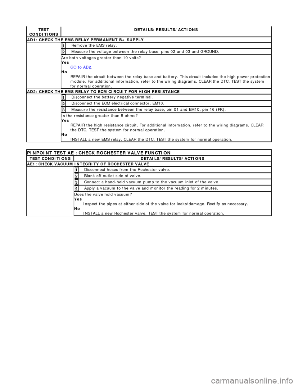
PINPOINT TEST AE : CHECK
ROCHESTER VALVE FUNCTION
T
E
ST CONDITIONS
D
E
TAILS/RESULTS/ACTIONS
AE1: CHEC
K VAC
UUM INTEGRITY OF ROCHESTER VALVE
Di
sc
onnect hoses from the Rochester valve.
1
Bl
a
nk off outlet side of valve.
2
Con
n
ect a hand-held vacuum pump to the vacuum inlet of the valve.
3
Appl
y a vacuum t
o the valve and mo
nitor the reading for 2 minutes.
4
Do
es the valve hold vacuum?
Yes Inspect the pipes at either side of the valve for leaks/damage. Rectify as necessary.
No INSTALL a new Rochester valve. TEST the system for normal operation.
Page 1769 of 2490
Air Distribution and Filtering - Air Distri
bution and Filtering
Description an
d Operation
Air Distribution
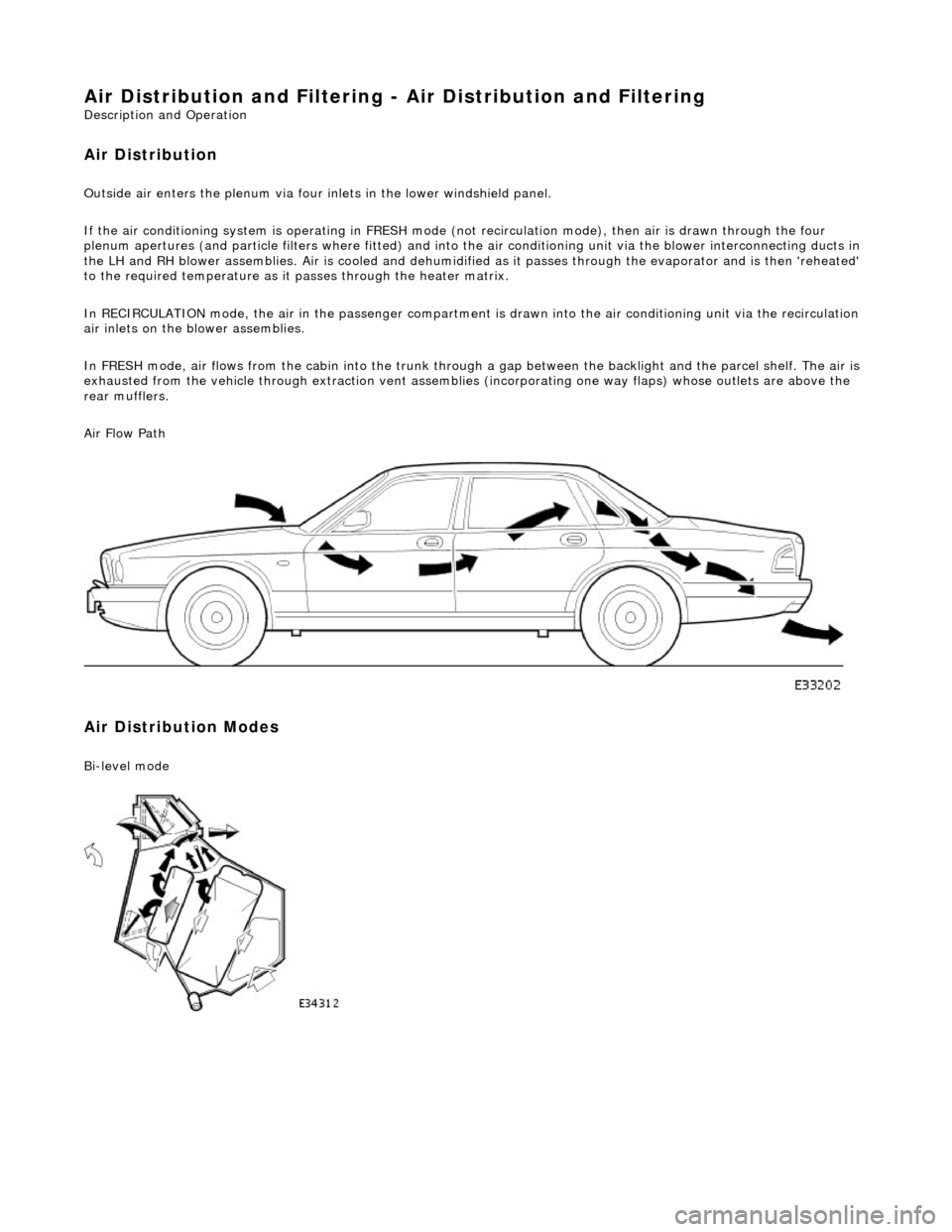
Ou
tside air enters the plen
um via four inlets in the lower windshield panel.
If the air conditioning system is operating in FRESH mode (not recirculation mode), then air is drawn through the four
plenum apertures (and particle filters where fitted) and into the air conditioni ng unit via the blower interconnecting ducts in
the LH and RH blower assemblies. Air is c ooled and dehumidified as it passes through the evaporator and is then 'reheated'
to the required temperature as it passes through the heater matrix.
In RECIRCULATION mode, the air in the pass enger compartment is drawn into the air conditioning unit via the recirculation
air inlets on the blower assemblies.
In FRESH mode, air flows from the cabin into the trunk through a gap between the backlight and the parcel shelf. The air is
exhausted from the vehicle through extraction vent assemblies (incorporating one way flaps) whose outlets are above the
rear mufflers.
Air Flow Path
Air Distribution Modes
Bi
-level mode
Page 1773 of 2490
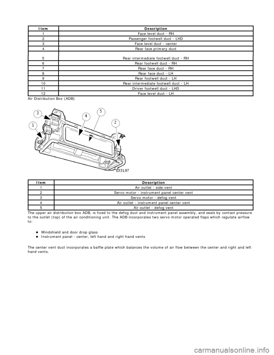
Ai
r Distribution Box (ADB)
The upper air distribution box ADB, is fixed to the defog duct and instrument panel assembly, and seals by contact pressure
to the outlet (top) of the air conditioning unit. The ADB inco rporates two servo motor operated flaps which regulate airflow
to:
Windshield and door drop
glass
Instrument panel
- center, left
hand and right hand vents
The center vent duct incorporat es a baffle plate which balances the volume of air flow between the center and right and left
hand vents.
5R
ear intermediate footwell duct - RH
6R
ear footwell duct - RH
7R
ear face duct - RH
8R
ear face duct - LH
9R
ear footwell duct - LH
10R
ear intermediate footwell duct - LH
11D
river footwell duct - LHD
12Fac
e level duct -
LH
It
em
De
scription
1Ai
r outlet - side vent
2Servo motor -
instrume
nt panel center vent
3Servo motor -
defog vent
4Ai
r outlet - instrume
nt panel center vent
5Ai
r outlet - defog vent
It
em
De
scription
1Fac
e level duct - RH
2Passenger footwel
l duct - LHD
3Fac
e level duct - center
4Rear
face primary duct
Page 1774 of 2490
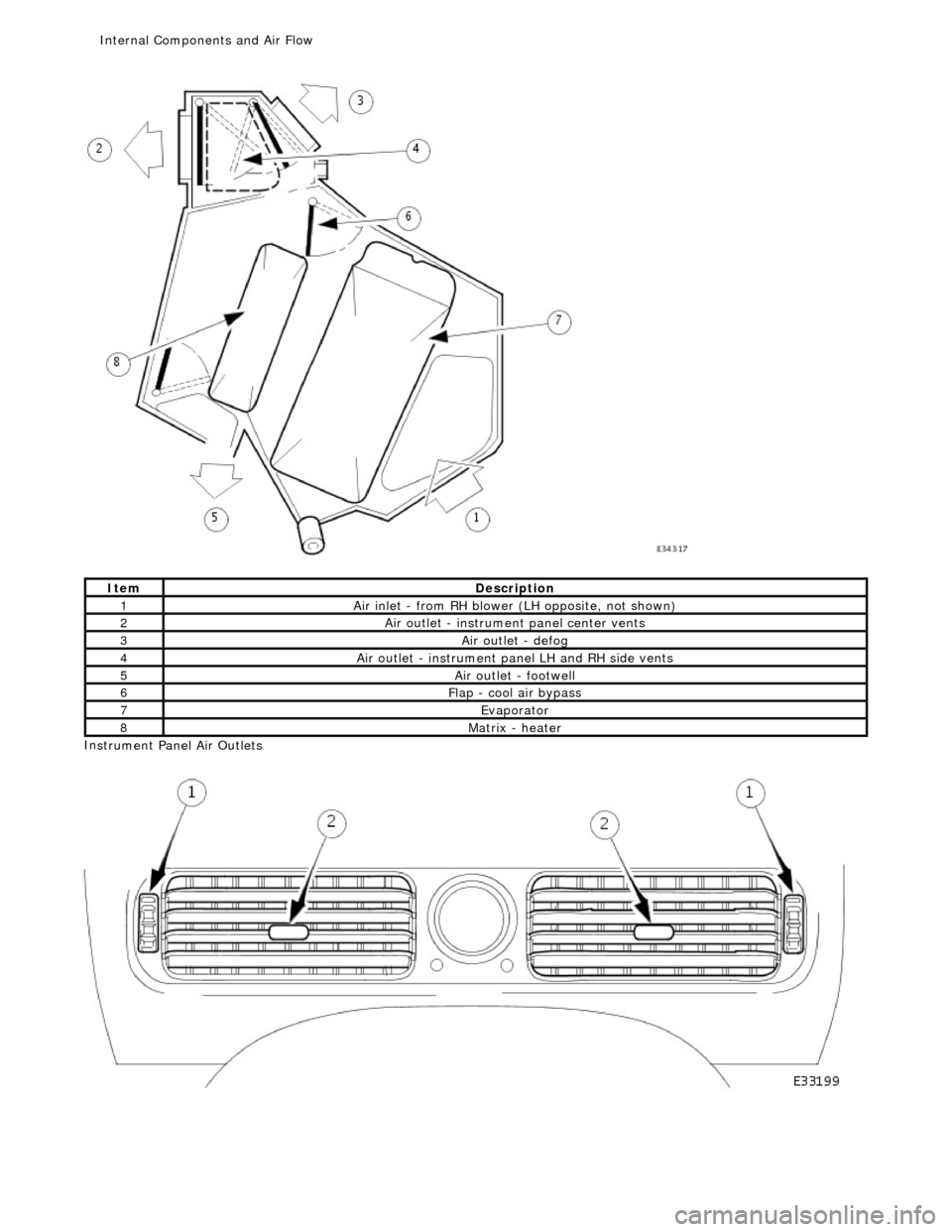
I n
strument Pane
l Air Outlets
Ite
m
De
scr
iption
1Ai
r i
nlet - from RH blower (LH opposite, not shown)
2Ai
r outl
et - instrument
panel center vents
3Air ou
tlet - defog
4Ai
r outl
et - instru
ment panel LH and RH side vents
5Air outl
et - footwell
6Flap -
cool air
bypass
7Evaporator
8Matrix -
heater
Internal Components and Ai
r Fl
ow
Page 1775 of 2490
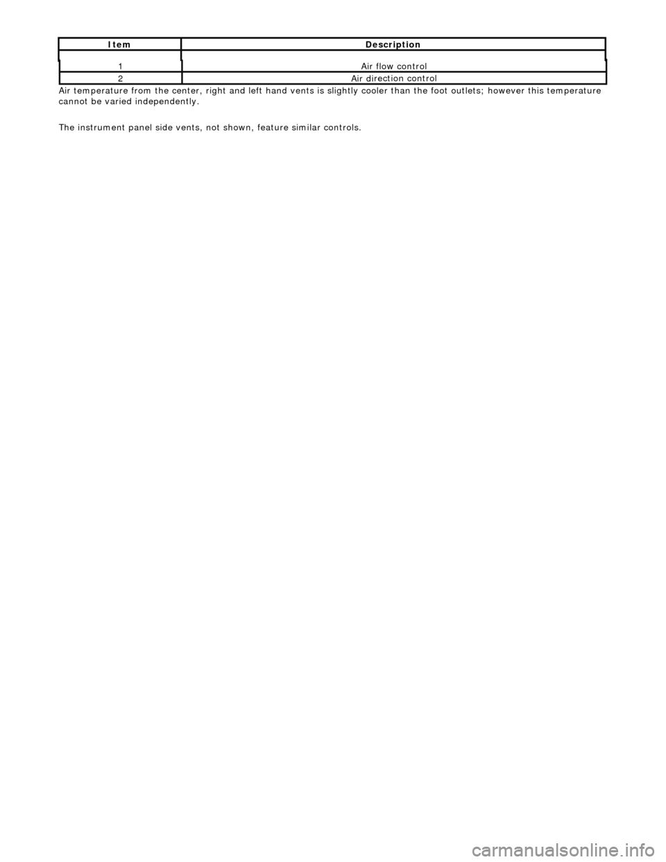
Ai
r temperature from the center, right and left
hand vents is slightly cooler than the foot outlets; however this temperature
cannot be varied independently.
The instrument panel side vents, not shown, feature similar controls.
1Ai
r flow control
2Air di
rection control
It
em
De
scription
Page 1784 of 2490
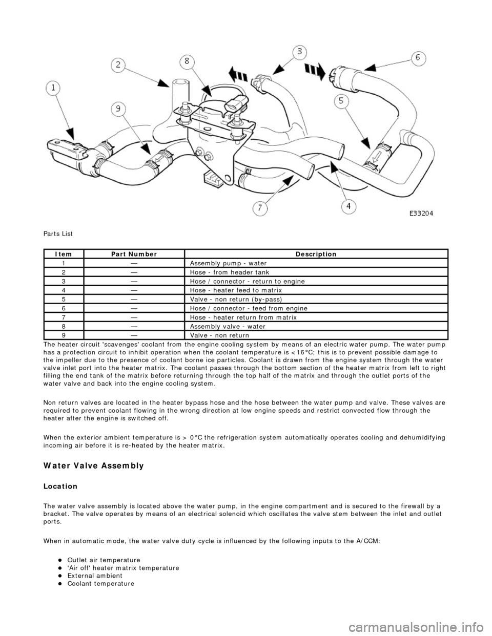
Parts List
The heater circuit 'scavenges' coolant from the engine cooling system by mean s of an electric water pump. The water pump
has a protection circuit to inhibit operation when the coolant temperature is <16°C; this is to prevent possible damage to
the impeller due to the presence of coolant borne ice particles. Coolant is drawn from the en gine system through the water
valve inlet port into the heater matrix. The coolant passes thro ugh the bottom section of the heater matrix from left to right
filling the end tank of the matrix before returning through the top half of the ma trix and through the outlet ports of the
water valve and back into the engine cooling system.
Non return valves are located in the heat er bypass hose and the hose between the water pump and valve. These valves are
required to prevent coolant flowing in th e wrong direction at low engine speeds and restrict convected flow through the
heater after the engine is switched off.
When the exterior ambient temperature is > 0°C the refrigerat ion system automatically operates cooling and dehumidifying
incoming air before it is re -heated by the heater matrix.
Water Valve Assembly
Location
The water valve assembly is located above the water pump, in the engine compartmen t and is secured to the firewall by a
bracket. The valve operates by means of an electrical solenoid which oscillates the valve stem between the inlet and outlet
ports.
When in automatic mode, the water valve duty cycle is influenced by the following inputs to the A/CCM:
Outlet air temperature 'Air off' heater matrix temperature External ambient Coolant temperature
ItemPart NumberDescription
1—Assembly pump - water
2—Hose - from header tank
3—Hose / connector - return to engine
4—Hose - heater feed to matrix
5—Valve - non return (by-pass)
6—Hose / connector - feed from engine
7—Hose - heater return from matrix
8—Assembly valve - water
9—Valve - non return