Page 1122 of 2490

Intake Air Distribution and Filtering - Charge Air Cooler RH
Remo
val and Installation
Remov
a
l
Installation
1. Disc onne
ct battery ground cable (IMPORTANT, see SRO
86.15.19 for further information).
2. Drain radiator coolant; refer to 26.10.01.
3. Remove air cleaner cover / intake assembly; refer to 19.10.30.
4. Remove throttle body; refer to 19.70.04.
5. Remove exhaust gas re-circulation valve (EGR) if installed;
refer to 17.45.01.
6. Remove throttle intake elbo w; refer to (SC) 19.70.28.
7. Remove supercharger outlet duct; refer to 18.50.16.
8. Remove coolant outlet pipe; refe r to operation (SC) 26.31.08.
9. Remove supercharger drive belt; refer to 18.50.08.
10. Remove supercharger; refer to operation 18.50.15.
11. Remove intake air temperatur e sensor 2 from charge air
cooler; refer to 18.30.52.
12. Detach engine harness retaining clip from rear of charge air
cooler.
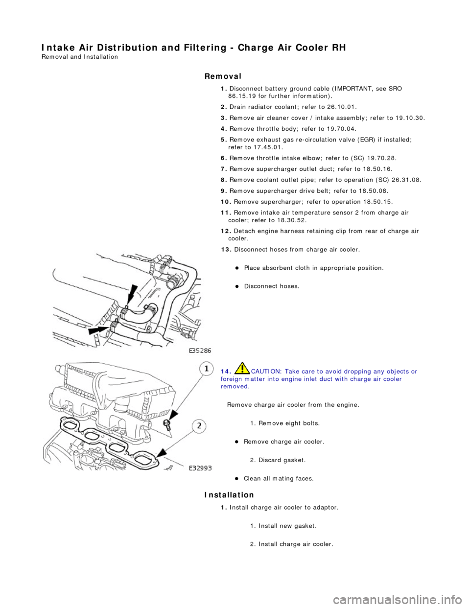
13. Di
sconnect hoses from charge air cooler.
Pla
ce absorbent cloth in appropriate position.
Di
sc
onnect hoses.
14 . CAUTI
ON: Take care to avoi
d dropping any objects or
foreign matter into engine inle t duct with charge air cooler
removed.
Remove charge air cooler from the engine. 1. Remove eight bolts.
Remove charge air cooler.
2
. Discard gasket.
Cle
a
n all mating faces.
1.
Install ch arge air
cooler to adaptor.
1. Install new gasket.
2. Install charge air cooler.
Page 1123 of 2490
2.
Conne
ct hoses to charge air cooler.
Conne
ct hoses.
3. Install intake air te mperature sensor 2 to charge air cooler;
refer to 18.30.52.
4. Install supercharger; refer to 18.50.15.
5. Install supercharger driv e belt; refer to 18.50.08.
6. Install engine coolant outlet pipe; refer to 26.31.08.
7. Install supercharger outlet du ct and new gasket; refer to
18.50.16.
8. Install throttle intake elbow; refer to 19.70.28.
9. Install exhaust gas re-circulation valve (EGR) if applicable;
refer to 17.45.01.
10. Install throttle body; refer to 19.70.04.
11. Install air cleaner cover / intake assembly; re fer to 19.10.30.
12. Refill cooling system; refer to (SC) (26.10.01).
13. Reconnect battery ground cable (IMPORTANT, see SRO
86.15.15 for further information).
Page 1128 of 2490

Intake Air Distribution and Filtering - Supercharger
Remo
val and Installation
Remov
a
l
Installation
1. Disc onne
ct battery ground cable (IMPORTANT, see SRO
86.15.19 for further information).
2. Drain radiator coolant; refer to 26.10.01.
3. Remove air cleaner cover / intake assembly; refer to 19.10.30.
4. Remove throttle body; refer to 19.70.04.
5. Remove exhaust gas re-circulation valve (EGR) if installed;
refer to 17.45.01.
6. Remove throttle intake elbo w; refer to (SC) 19.70.28.
7. Remove supercharger outlet duct; refer to 18.50.16.
8. Remove coolant outlet pipe; refe r to operation (SC) 26.31.08.
9. Remove supercharger drive belt; refer to 18.50.08.
10. Disconnect remaining coolant hoses from charge air coolers.
Position pipes to facilitate removal
of supercharger.
Inst
al
l suitable blanking plugs.
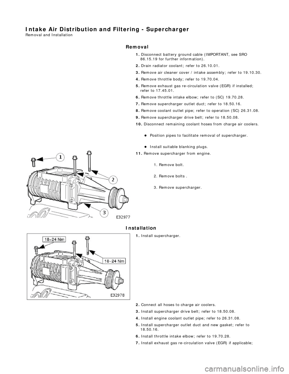
11 .
R
emove supercharger from engine.
1. Remove bolt.
2. Remove bolts .
3. Remove supercharger.
1. Inst al
l supercharger.
2. Connect all hoses to charge air coolers.
3. Install supercharger driv e belt; refer to 18.50.08.
4. Install engine coolant outlet pipe; refer to 26.31.08.
5. Install supercharger outlet du ct and new gasket; refer to
18.50.16.
6. Install throttle intake elbow; refer to 19.70.28.
7. Install exhaust gas re-circulation valve (EGR) if applicable;
Page 1130 of 2490

Intake Air Distribution and Filtering - Supercharger Outlet Pipe
Remo
val and Installation
Remov
a
l
1.
Re
move air cleaner cover / intake
assembly; refer to 19.10.30.
2. Drain radiator coolant; refer to operation (SC) 26.10.01.
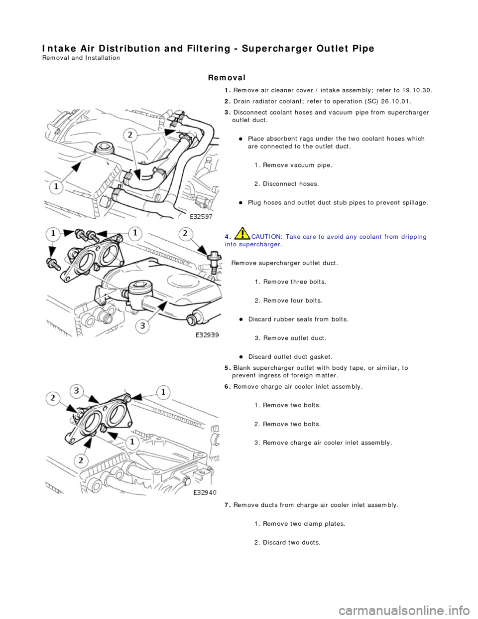
3. Disc
onnect coolant hoses and vacuum pipe from supercharger
outlet duct.
Pl a
ce absorbent rags under
the two coolant hoses which
are connected to the outlet duct.
1. Remove vacuum pipe.
2. Disconnect hoses.
Plu g
hoses and outlet duct stub pipes to prevent spillage.
4. CAUTIO
N: Take care to avoi
d any coolant from dripping
into supercharger.
Remove supercharger outlet duct. 1. Remove three bolts.
2. Remove four bolts.
Di
scard rubber seals from bolts.
3. Remove outlet duct.
Discard ou
tlet duct gasket.
5.
Bla
nk supercharger outlet with
body tape, or similar, to
prevent ingress of foreign matter.
6. Remove charge air c oo
ler inlet assembly.
1. Remove two bolts.
2. Remove two bolts.
3. Remove charge air cooler inlet assembly.
7. Remove ducts from charge air cooler inlet assembly.
1. Remove two clamp plates.
2. Discard two ducts.
Page 1131 of 2490
I
nstallation
8.
Cl
ean all relevant parts and mating faces.
1. Re-assemble charge air cooler clamp inlet assembly.
Use
new ducts.
2. Install ch
arge air cooler inlet as
sembly to charge air coolers.
3. CAUTION: Take care to avoid ingress of dirt or foreign
matter into the supercharger.
Install supercharger outlet duct. 1. Remove blanking tape from outlet port of
supercharger.
Cl
ean supercharger outlet mating face.
2. Install new gasket.
3. Install duct.
4. Install new rubber seals to the four bolts.
Page 1132 of 2490
4. Secure charge air cool
er inlet as
sembly to supercharger outlet
duct.
1. Install bolts.
5. Inst al
l coolant hoses and vacuum pipe to outlet duct.
1. Install vacuum pipe.
2. Install coolant hoses.
6. Refill cooling system; refer to (SC) (26.10.01).
7. Install intake tube / air fl ow meter / air cleaner cover
assembly; refer to 19.10.30.
Page 1133 of 2490
Intake Air Distribution and Filtering - Su
percharger Outl
et Pipe Gasket
Re
moval and Installation
Remov
al
Installation
1.
R
emove supercharger outlet
duct; refer to 18.50.16.
1. Installation is a reversal of the removal procedure.
Page 1148 of 2490

Evaporative E
missions - Evaporative Emissions
Description an
d Operation
To reduce the emission of fuel vapour, th e fuel tank is vented to atmosphere through activated charcoal adsorption canister
(s) which collects the fuel droplets. The ch arcoal is periodically purged of fuel when the EVAP Canister Purge Valve opens
the vapour line between the canister(s) and the air intake induct ion elbow. This action allows manifold depression to draw
air through the canister atmospheric vent, taking up the deposited fuel from the charcoal adsorber and burning the resulting
fuel vapour in the engine.
The EVAP Canister Purge Valve is controlled by the engine management system ECM. Purging is carried out in accordance
with the engine management fu eling strategy (see below).
The fuel tank vapour outlet is via a removeable flange assemb ly on the top surface of the tank. The vapour storage canister
or canisters are fitted on the underside of the vehicle below the rear seats.
There are three variants of the evaporativ e system. All systems use the charcoal adsorber storage canisters and purge valve
and operate as described above. The specific features of each system are described below. The evaporative systems are
designated as :
sin g
le canister system
ru
nn
ing loss system
ru
nn
ing loss with On-board Re-fueling Vapour Recovery (ORVR) system
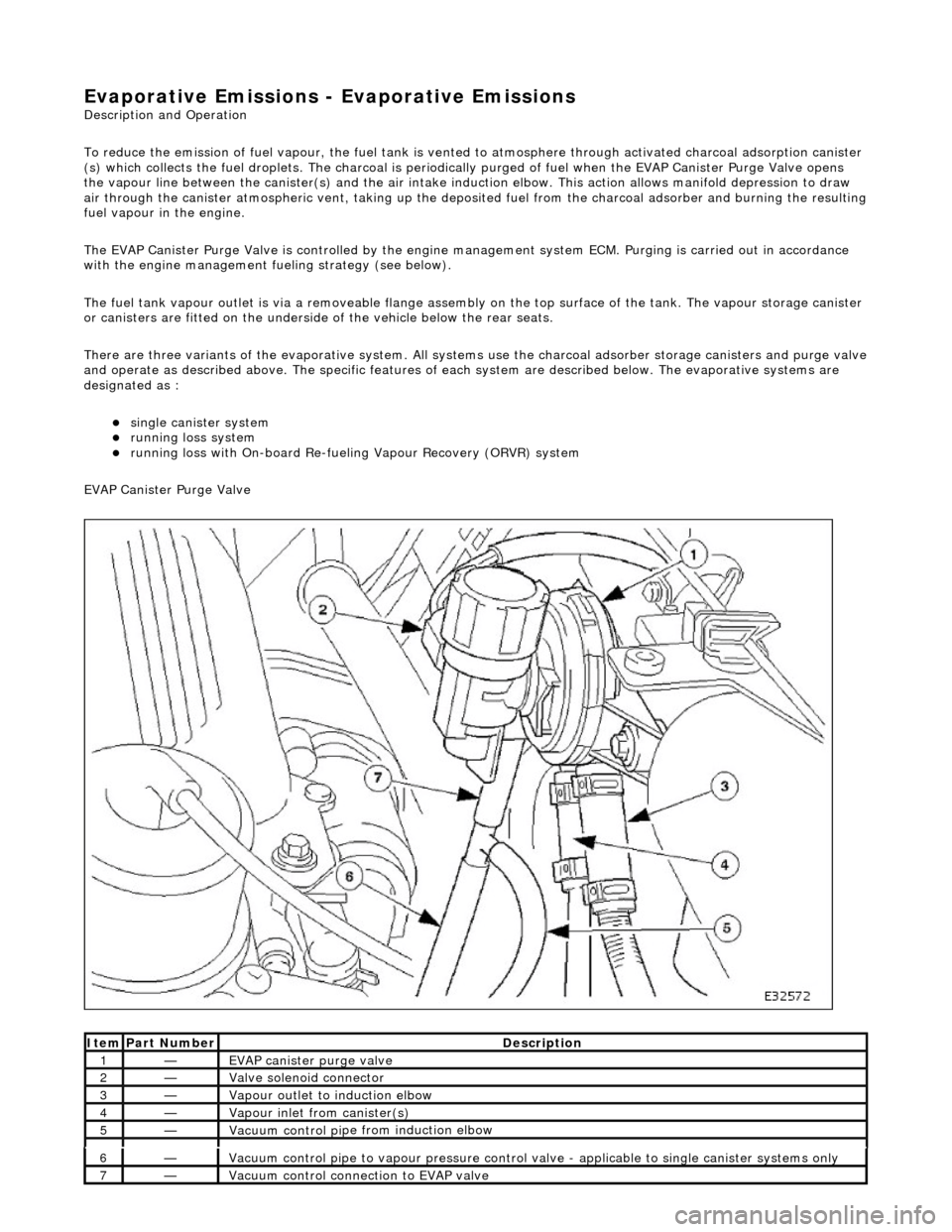
EVAP Canister Purge Valve
Ite
m
Par
t
Number
De
scr
iption
1—EVAP canister purge v
alve
2—Valve s
olenoid connector
3—Vapour outlet to indu
ction elbow
4—Vapour
inlet from canister(s)
5—Vacuum contro
l pi
pe from induction elbow
6—Vacuum contro
l pi
pe to vapour pressure control va
lve - applicable to single canister systems only
7—Vacuum
control connection to EVAP valve