Page 1873 of 2490
Parking Aid - Rear Parking Aid Sensor
Removal and Installation
Removal
Installation
1.
Raise and support the vehicle.
For additional information, refer to: Jacking
(100-02 Jacking
and Lifting, Descript ion and Operation).
2. Disconnect the electrical connector.
3. CAUTION: Make sure excessiv e pressure or tools are not
used when removing the parkin g aid sensor from the housing.
Remove the rear parking aid sensor.
1. To install, reverse the removal procedure.
Page 1919 of 2490

Exterior Lighting - Exterior Lighting
Description and Operation
A multi-function switch located on the left stalk of the steering column switch assembly permits selection of either parking
(side), headlamps, auto-headlamp or off. Selection of a particular mode provides the appropriate input to the body
processor module (BPM).
Where the auto headlamp function is incorporated, a light sensor in the interior rear view mirror monitors ambient light and
provides an input to the BPM. The BPM responds by switching the low beam headlamps on or off as appropriate for the
prevailing light conditions.
The front and rear fog lamp switch is located on the fascia outboard of the steering column.
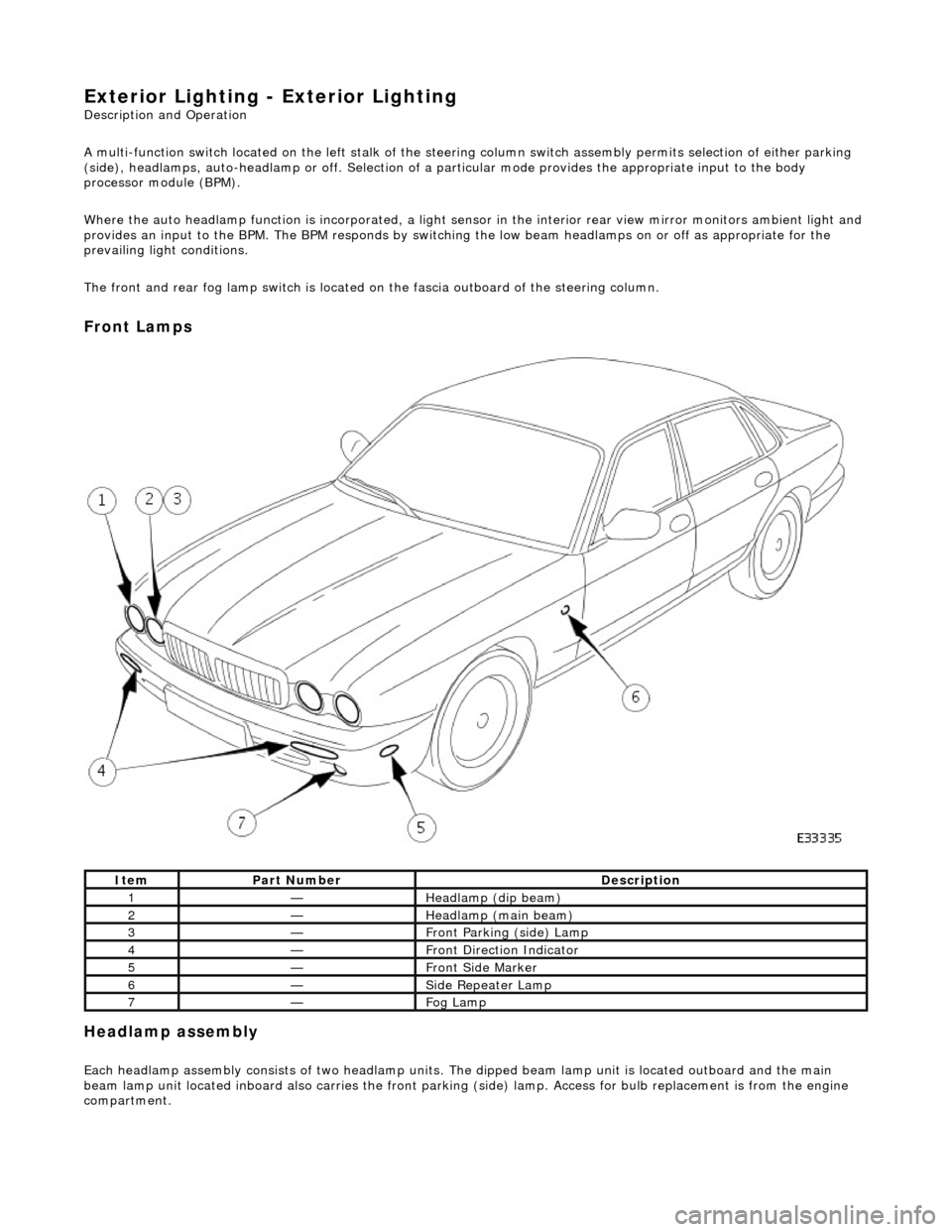
Front Lamps
Headlamp assembly
Each headlamp assembly consists of tw o headlamp units. The dipped beam lamp unit is located outboard and the main
beam lamp unit located inboard also carries the front parking (side) lamp. Access for bulb replacement is from the engine
compartment.
ItemPart NumberDescription
1—Headlamp (dip beam)
2—Headlamp (main beam)
3—Front Parking (side) Lamp
4—Front Direction Indicator
5—Front Side Marker
6—Side Repeater Lamp
7—Fog Lamp
Page 1976 of 2490

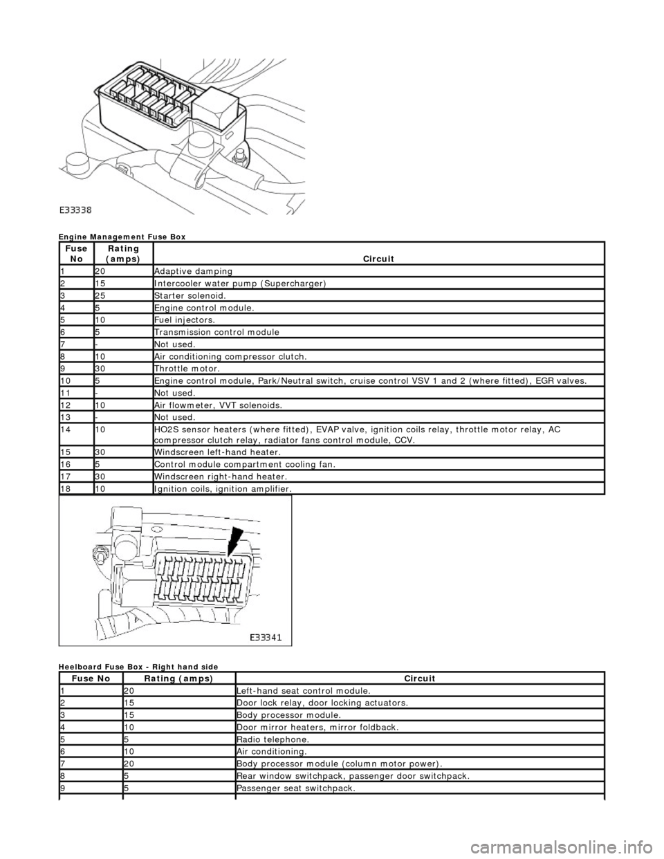
Engine Management Fuse Box
Heelboard Fuse Box - Right hand side
Fuse NoRating
(amps)Circuit
120Adaptive damping
215Intercooler water pump (Supercharger)
325Starter solenoid.
45Engine control module.
510Fuel injectors.
65Transmission control module
7-Not used.
810Air conditioning compressor clutch.
930Throttle motor.
105Engine control module, Park/Neutr al switch, cruise control VSV 1 and 2 (where fitted), EGR valves.
11-Not used.
1210Air flowmeter, VVT solenoids.
13-Not used.
1410HO2S sensor heaters (where fitted ), EVAP valve, ignition coils relay, throttle motor relay, AC
compressor clutch relay, radi ator fans control module, CCV.
1530Windscreen left-hand heater.
165Control module compartment cooling fan.
1730Windscreen right-hand heater.
1810Ignition coils, ignition amplifier.
Fuse NoRating (amps)Circuit
120Left-hand seat control module.
215Door lock relay, door locking actuators.
315Body processor module.
410Door mirror heaters, mirror foldback.
55Radio telephone.
610Air conditioning.
720Body processor module (column motor power).
85Rear window switchpack, passenger door switchpack.
95Passenger seat switchpack.
Page 1989 of 2490

Wiring Harnesses - Wiring Harness
Description and Operation
Introduction
CAUTION: Do not use any other heat shrink sleeve other than the approved glue lined heat shrink sleeve mentioned
in the repair procedure.
The purpose of this document is to promote quick and efficient minor repair to harness connectors or cables using approved
methods and the wiring harness repair kit. Repairs may only be made to cables and connectors which have been
mechanically, not electrically damaged. It also applies wher e the whole extent of the damage can be clearly identified and
rectified.
Care and neatness are essential requir ements in making a perfect repair.
Caution:
At the time of this first issue of the Harness Repair Guide, do not approve re pairs to any of the following circuits:
Any media orientated system transport network harnesses. Supplement restraint system (SRS) firing circuits (Air bags). Link lead assembles, which are unique to safety critical circuits such as anti-lock brake system (ABS) and
thermocouple circuits. An example of this is the ABS wheel speed sensors with moulded connectors.
4. Screened cables, leads and wiring harness(s).
If any harness(s) with defective electrical connector te rminals or wires from the above circuits are a concern,
new components must be installed.
Repair Kit
CAUTION: Where the repair procedure indica tes that a glue lined heat shrink sleeve should be applied, apply sufficient
heat to the glue lined heat shrink to melt the glue in order to provide a water tight seal. Do not over heat the glue lined
heat shrink sleeve so that the wiring harness insulation becomes damaged.
The wiring harness repair kit has been produced which comprises:
Pre-terminated wiring harness(s) of different sizes and types Three sizes of butt splice connectors A selection of colored cable identification sleeves Two sizes of glue lined heat shrink sleeves Crimping pliers A wire cutter and insulation stripper An electrical connector terminal extraction handle and tips
A suitable heat source, fo r shrinking heat shrink sleeves will be required.
The pre-insulated diamond grip range of el ectrical connector terminals and in-line, butt splice connectors contained within
the wiring harness repair kit are the only acceptable product for the repairs of wi ring harnesses. The butt connectors not
only grip the wire but also the insu lation, making a very secure joint.
If an electrical connector terminal is not included in the wiring harness repair kit then approval for the repair is NOT given
and in these circumstances a new wi ring harness must be installed.
Pre-Terminated Wiring Harness( s) and Butt Splice Connectors
All pre-terminated wiring harness(s) and butt splice connectors in the wiring harness repair kit are contained in bags which
can be resealed after use. Each bag is marked with the part number of the items stored within the bag. Each storage
compartment in the wiring harness repair kit is identified with the corresponding part number. Make sure that pre-
terminated wiring harness(s) and connectors are not mixed up it is advisable to only open one bag at a time and to reseal
Page 2077 of 2490
Installation
All vehicles
Remove the retaining screw.
10. With the aid of another tech nician, lower the headliner.
11. With the aid of another techni cian, remove the headliner.
12. NOTE: Left-hand shown, right-hand similar.
Detach the anti-theft sensors.
13. NOTE: Left-hand shown, right-hand similar.
Remove the anti-t heft sensors.
1. Disconnect the electrical connector.
1. NOTE: Left-hand shown, right-hand similar.
Page 2078 of 2490
Install the anti-theft sensors. 1. Connect the electrical connector.
2. NOTE: Left-hand shown, right-hand similar.
Attach the anti-theft sensors.
3. CAUTION: With the aid of an other technician, support the
headliner.
Install the headliner.
4. With the aid of another tech nician, raise the headliner.
5. CAUTION: Support the headliner to ensure it is not folded or creased during installation.
• NOTE: Left-hand shown, right-hand similar.
Install the headliner retaining trims.
Install the retaining screw.
6. NOTE: Left-hand shown, right-hand similar.
Attach the screw cover.
Page 2113 of 2490
Rear View Mirrors - Auto-Dimming Interior Mirror
Removal and Installation
Removal
Installation
1.
Remove roof console for access and disconnect interior mirror
harness multiplugs. Refer to 76.13.69.90.
2. Remove upper cover from mirror stem.
3. Remove rain sensor unit. Refer to Section 501.16.
4. CAUTION: When removing mirror from base, care must
be exercised to ensure that base is not detached from windshield.
Applying firm downward pre ssure, remove mirror assembly
from base.
1. Position mirror at bottom of base and apply firm upward
pressure to fully seat and secure in position.
2. Install upper cover to mirror stem.
3. Position roof console at head er and connect mirror harness
multiplugs.
4. Install rain sensor unit. Refer to Section 501.16.
5. Install roof console. Refer to 76.13.69.
Page 2118 of 2490
Rear View Mirrors - Interior Mirror
Removal and Installation
Removal
CAUTION: When removing mirror from base, care must be exercised to ensure that base is not detached from
windshield.
Installation
1. Remove upper cover from mirror stem.
2. Remove rain sensor unit. Refer to Section 501.16.
3. Applying firm downward pre ssure, remove mirror assembly
from base.
1. Position mirror at bottom of base and apply firm upward
pressure to fully seat and secure in position.
2. Install rain sensor unit. Refer to Section 501.16.
3. Install upper cover to mirror stem.