Page 2368 of 2490
Supplemental Restraint System -
Torques
ComponentNm
Screws, front seat belt height adjuster to B/C post LH and RH24 - 26
Nut, seat belt upper anchor to height adjuster LH and RH30 - 40
Bolt, LH and RH rear seat belt lower anchor to BIW30 - 40
Bolt, centre rear seat belt lower anchor to BIW30 - 40
Bolts, rear seat belt automatic locking re tractor LH, RH and centre to squab panel30 - 40
Bolt, rear seat belt buckle LH, RH and centre to BIW30 - 40
Bolt, front seat belt buckle LH and RH to seat rail30 - 40
Bolt, front seat belt lower an chor LH and RH to seat rail30 - 40
Bolts, front seat belt automatic lock ing retractor/pretensioner to B post30 - 40
Bolts, side airbag to seat frame9 - 11
Screws, front seat belt guide to B/C post8 - 10
Screws, single point sensor to tunnel5 - 7
Screws, side impact sens ing module to 'B' post5 - 7
Page 2379 of 2490

Supplemental Restraint System - Side Impact Sensor
Removal and Installation
Removal
• WARNINGS:
FOLLOWING DISCONNECTION OF THE BA TTERY, A PERIOD OF AT LEAST FIFTEEN MINUTES MUST BE ALLOWED TO
ELAPSE BEFORE DISCONNECTING THE SINGLE-POINT SENSING (SPS) UNIT.
IN THE EVENT OF A FAULT RUPTURING THE 10A BATTER Y SUPPLY FUSE (F4 LOCATED IN THE FUSE-BOX AT THE
DRIVER'S END OF THE FASCIA), THE FUSE MUST NOT BE RENEWED UNTIL THE AIRBAG/SRS SYSTEM HAS BEEN DE-
ACTIVATED. FUSES OF ANY OTHER VALUE MUST NEVER BE USED, AS THIS CAN CAUSE DISARM FAILURE.
Installation
1. Remove battery cover and disconnect ground cable from battery
terminal. Refer to 86.15.19.
2. Remove'B' post trim pa d. Refer to 76.13.08.
3. Remove seat belt upper anchor and seat belt guide. Refer to
76.73.10
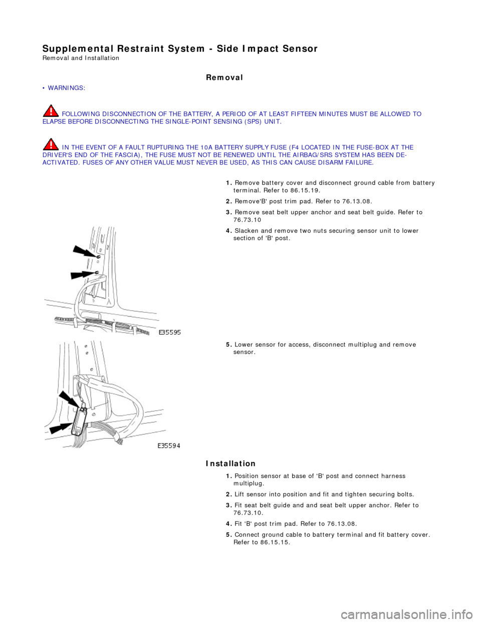
4. Slacken and remove two nuts securing sensor unit to lower
section of 'B' post.
5. Lower sensor for access, disco nnect multiplug and remove
sensor.
1. Position sensor at base of 'B' post and connect harness
multiplug.
2. Lift sensor into position and fit and tighten securing bolts.
3. Fit seat belt guide and and seat belt upper anchor. Refer to
76.73.10.
4. Fit 'B' post trim pad. Refer to 76.13.08.
5. Connect ground cable to battery terminal and fit battery cover.
Refer to 86.15.15.
Page 2408 of 2490
Inset A, shows the 25° - 35°angled cut-away at front edge. The front end of the coachlines should terminate 50mm - 60mm behind the headlamp apertures and the two sides must be symmetrical.
The 1.25mm - 1.75mm wide coachline (inset B), terminates with vertical face and ends 10mm - 20mm forward of tail lamp
aperture.
Inset C shows the upper edge of the coac hline positioned 6mm - 8mm below feature line along the body side. Inset D shows
gap dimensions and lower coachline width.
Details of front end lower coachlines, including position of the lower coachline relative to door mouldings and front wings are
shown in Inset E.
Inset F shows lower coachline rear end detail.
Other Models
Page 2409 of 2490

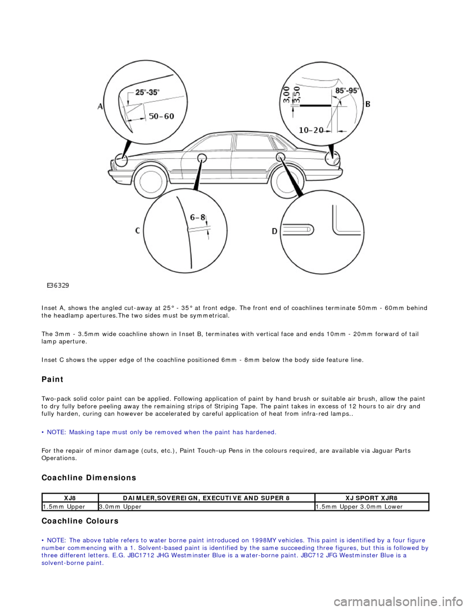
Inset A, shows the angled cut-away at 25° - 35° at front edge. The front end of coachlines terminate 50mm - 60mm behind
the headlamp apertures.The two sides must be symmetrical.
The 3mm - 3.5mm wide coachline shown in Inset B, terminates with vertical face and ends 10mm - 20mm forward of tail
lamp aperture.
Inset C shows the upper edge of th e coachline positioned 6mm - 8mm be low the body side feature line.
Paint
Two-pack solid color paint can be applied. Following application of paint by hand brus h or suitable air brush, allow the paint
to dry fully before peeling away the remain ing strips of Striping Tape. The paint takes in excess of 12 hours to air dry and
fully harden, curing can however be accelerated by careful application of heat from infra-red lamps..
• NOTE: Masking tape must only be removed when the paint has hardened.
For the repair of minor damage (cuts, et c.), Paint Touch-up Pens in the colours required, are available via Jaguar Parts
Operations.
Coachline Dimensions
Coachline Colours
• NOTE: The above table refers to water borne paint introduced on 1998MY vehicles. This paint is identified by a four figure
number commencing with a 1. Solvent-based paint is identified by the same succeeding three figures, but this is followed by three different letters. E.G. JBC1712 JHG Westminster Blue is a water-borne paint. JBC712 JFG Westminster Blue is a
solvent-borne paint.
XJ8DAIMLER,SOVEREIGN, EXECUTIVE AND SUPER 8XJ SPORT XJR8
1.5mm Upper3.0mm Upper1.5mm Upper 3.0mm Lower
Page 2411 of 2490

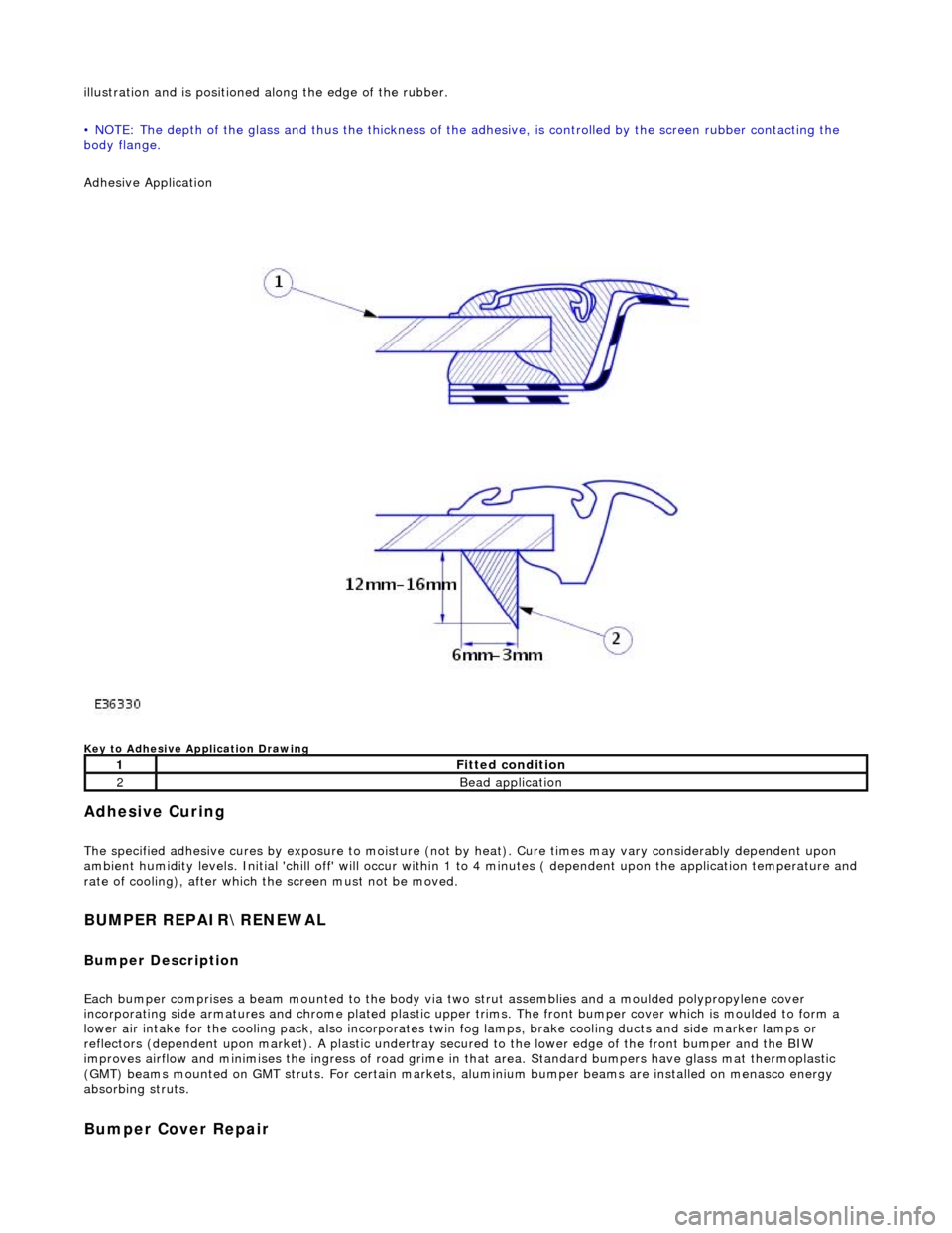
illustration and is positioned along the edge of the rubber.
• NOTE: The depth of the glass and thus the thickness of the ad hesive, is controlled by the screen rubber contacting the
body flange.
Adhesive Application
Key to Adhesive Application Drawing
Adhesive Curing
The specified adhesive cures by exposure to moisture (not by heat). Cure times may vary considerably dependent upon
ambient humidity levels. Initial 'chill off' will occur within 1 to 4 minutes ( dependent upon the application temperature and
rate of cooling), after which the screen must not be moved.
BUMPER REPAIR\RENEWAL
Bumper Description
Each bumper comprises a beam mounte d to the body via two strut assemblies and a moulded polypropylene cover
incorporating side armatures and chrome plated plastic upper trims. The front bumper cover which is moulded to form a
lower air intake for the cooling pack, also incorporates twin fog lamps, brake cooling ducts and side marker lamps or
reflectors (dependent upon market). A plastic undertray secured to the lower edge of the front bumper and the BIW
improves airflow and minimises the ingres s of road grime in that area. Standard bumpers have glass mat thermoplastic
(GMT) beams mounted on GMT struts. For certain markets, aluminium bumper beams are installed on menasco energy
absorbing struts.
Bumper Cover Repair
1Fitted condition
2Bead application
Page 2416 of 2490

Replacement bumper cover assemblies includer side armatures, which should be removed from discarded bumper
assemblies and rout ed for recycling.
BODY SIDE MOULDINGS
Description
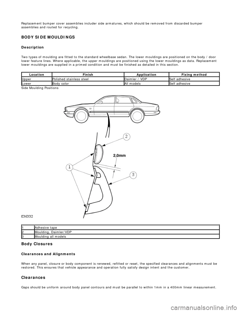
Two types of moulding are fitted to the standard wheelbase sedan. The lower mouldings are positioned on the body / door
lower feature lines. Where applicable, the upper mouldings are positioned using the lower mouldings as data. Replacement
lower mouldings are supplied in a primed condition and must be finished as detailed in this section.
Side Moulding Positions
Body Closures
Clearances and Alignments
When any panel, closure or body component is renewed, refitted or reset, the specified clearances and alignments must be
restored. This ensures that vehicle appearance and operation fully satisfy design intent and the customer.
Clearances
Gaps should be uniform around body panel contours and must be parallel to within 1mm in a 400mm linear measurement.
LocationFinishApplicationFixing method
UpperPolished stainless steelDaimler / VDPSelf adhesive
LowerBody colorAll modelsSelf adhesive
1Adhesive tape
2Moulding, Daimler/VDP
3Moulding all models
Page 2425 of 2490
Remove support from rack.
27. Ensure that steering is in central position.
28. Release lower steering column from pinion shaft.
1. Remove lower steering co lumn securing nut and bolt.
Move column upwards to release it from pinion shaft.
29. Support weight of crossbeam.
Position a jack under crossbeam.
Place a piece of wood between jack and crossbeam.
Raise jack to just support crossbeam.
30. From engine compartment, remove crossbeam front RH
securing bolts.
31. Remove power steering fl uid reservoir for access.
Remove reservoir securing nuts and bolts.
Position reservoir for access.
Page 2426 of 2490
32. From engine compartment, remove crossbeam front LH
securing bolts.
33. Remove crossbeam to engine Hydramount securing bolts.
Remove bolt securing cros smember to Hydramount.
Fully withdraw bolt into crossmember insert.
Repeat procedure to remove and withdraw bolt on
opposite side
34. CAUTION: To prevent damage to ball joints, secure
each hub assembly to suspensi on turret using strong wire.
Remove lower nut and bolt from front shock absorber.
Repeat procedure to remove bo lt from opposite side shock
absorber.
35. Remove crossbeam rear securing bolts.
Remove bolt from crossbeam LH rear mounting.
Repeat procedure to remove bolt from crossbeam RH rear
mounting.