Page 2045 of 2490

Body Closures - Hood Hinge
Removal and Installation
Removal
Installation
1.
CAUTION: Before slackening hi nge bolts, ensure that the
hood is sufficiently supported to prevent damage to paintwork
and gas support struts.
Remove cover from battery and disconnect ground cable from
battery terminal. Refer to 86.15.19.
2. Open hood and fit fender covers.
3. Remove radiator grille. Refer to 76.55.03.
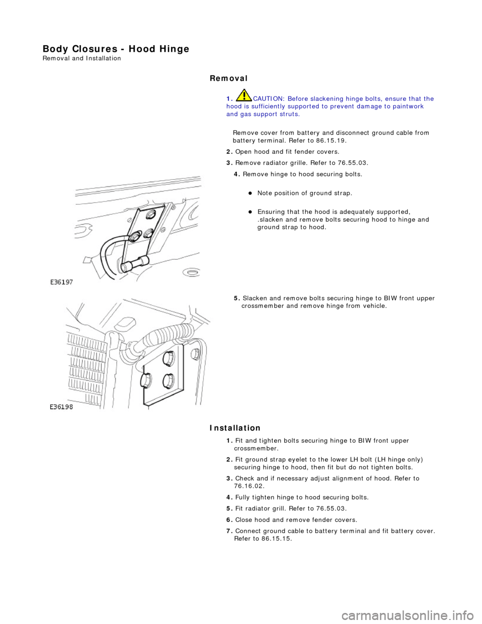
4. Remove hinge to hood securing bolts.
Note position of ground strap.
Ensuring that the hood is adequately supported,
.slacken and remove bolts se curing hood to hinge and
ground strap to hood.
5. Slacken and remove bolts securi ng hinge to BIW front upper
crossmember and remove hinge from vehicle.
1. Fit and tighten bolts securing hinge to BIW front upper
crossmember.
2. Fit ground strap eyelet to the lower LH bolt (LH hinge only)
securing hinge to hood, then fit but do not tighten bolts.
3. Check and if necessary adjust alignment of hood. Refer to
76.16.02.
4. Fully tighten hinge to hood securing bolts.
5. Fit radiator grill. Refer to 76.55.03.
6. Close hood and remove fender covers.
7. Connect ground cable to battery terminal and fit battery cover.
Refer to 86.15.15.
Page 2063 of 2490

Interior Trim and Ornamentation - Floor Covering
Removal and Installation
Removal
1. Remove battery cover and disc onnect ground cable from
battery terminal. Refer to 86.15.19.
2. Remove rear seat cushion. Refer to 76.70.37.
3. Remove front seats. Refer to 76.70.01
4. Remove 'J' gate surroun d. Refer to 76.25.24.
5. Remove centre console finish er veneer panel. Refer to
76.47.26.
6. Remove fascia centre veneer panel. Refer to 76.47.06.
7. Remove centre console assembly. Refer to 76.25.01.
8. Remove 'A' post lower trim pads. Refer to 76.13.30.
9. Remove 'B' post trim pads. Refer to operations in this section.
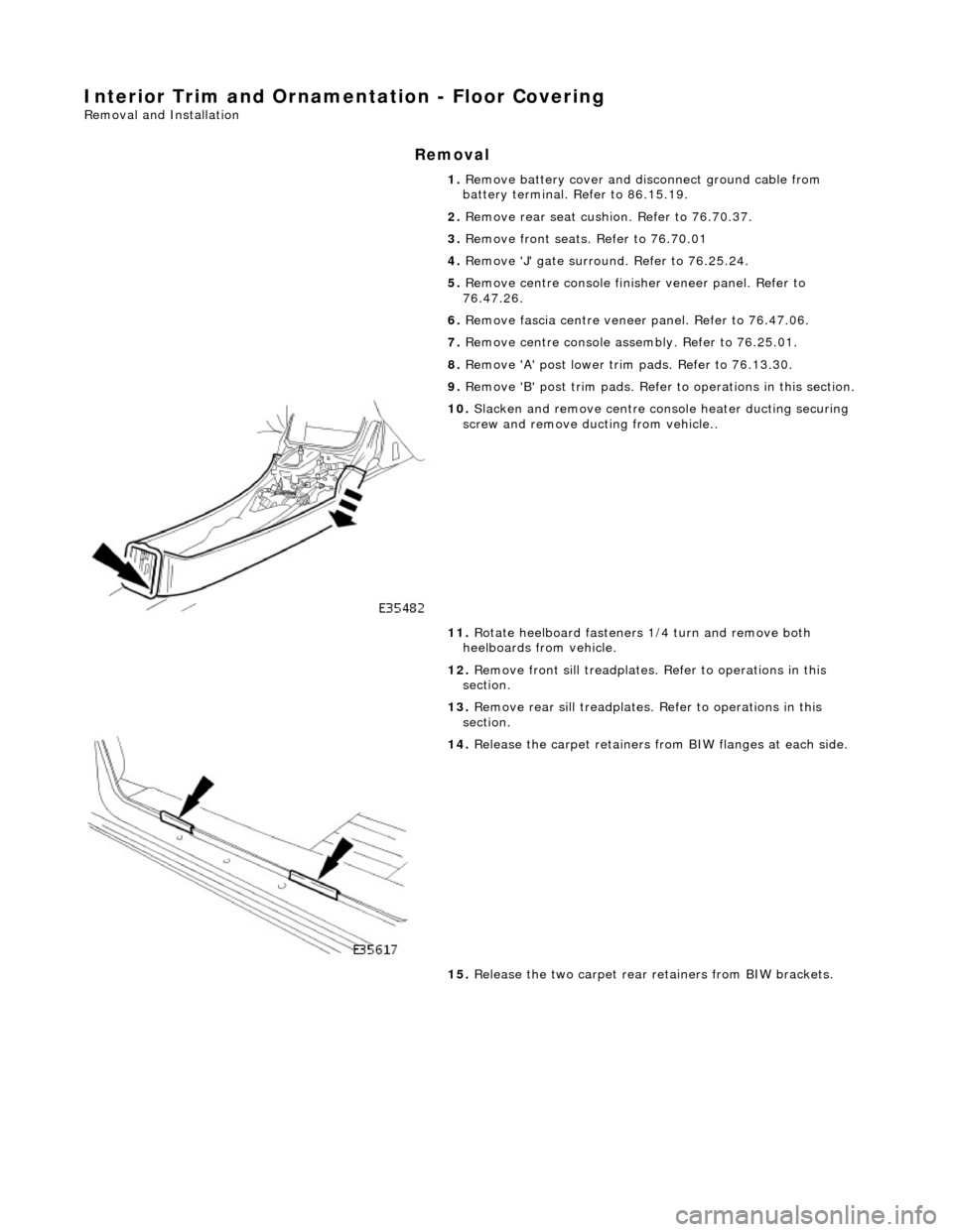
10. Slacken and remove centre console heater ducting securing
screw and remove ducting from vehicle..
11. Rotate heelboard fasteners 1/4 turn and remove both
heelboards from vehicle.
12. Remove front sill treadplates. Refer to operations in this
section.
13. Remove rear sill treadplates. Refer to operations in this
section.
14. Release the carpet retainers fro m BIW flanges at each side.
15. Release the two carpet rear retainers from BIW brackets.
Page 2065 of 2490

2. Ensure that
gear selector is in position 'R'.
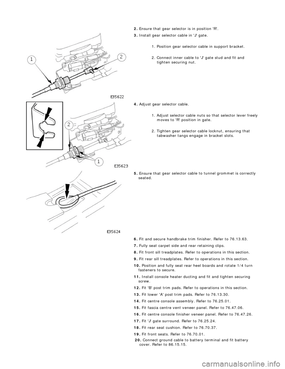
3. Inst
all gear selector cable in 'J' gate.
1. Position gear selector cable in support bracket.
2. Connect inner cable to 'J' gate stud and fit and
tighten securing nut.
4. Adjust
gear selector cable.
1. Adjust selector cable nuts so that selector lever freely
moves to 'R' position in gate.
2. Tighten gear selector ca ble locknut, ensuring that
tabwasher tangs engage in bracket slots.
5. Ensure that
gear selector cable
to tunnel grommet is correctly
seated.
6. Fit and secure handbrake trim finisher. Refer to 76.13.63.
7. Fully seat carpet side and rear retaining clips.
8. Fit front sill treadplates. Refer to operations in this section.
9. Fit rear sill treadplates. Refer to operations in this section.
10. Position and fully seat rear heel boards and rotate 1/4 turn
fasteners to secure.
11. Install console heater ducting and fit and tighten securing
screw.
12. Fit 'B' post trim pads. Refer to operations in this section.
13. Fit lower 'A' post trim pads. Refer to 76.13.30.
14. Fit centre console asse mbly. Refer to 76.25.01.
15. Fit fascia centre ve nt veneer panel. Refer to 76.47.06.
16. Fit centre console finisher vene er panel. Refer to 76.47.26.
17. Fit 'J' gate surround. Refer to 76.25.24.
18. Fit rear seat cushion. Refer to 76.70.37.
19. Fit front seats. Refer to 76.70.01.
20
.
Connect ground cable to batt ery terminal and fit battery
cover. Refer to 86.15.15.
Page 2070 of 2490
Interior Trim and Ornamentation - Front Door Armrest Removal and Installation
Removal
Installation
1.
Remove battery cover and disconnect ground cable from battery
terminal. Refer to 86.15.19.
2. Remove door casing. Refer to 76.34.01.
3. Slacken and remove four screws se curing armrest to door casing
and remove armrest from casing.
4. Remove switchpack from armrest.
1. Slacken and remove two screws securing switchpack and finisher to armrest.
2. Remove switchpack and finisher from armrest.
5. Slacken and remove two screws secu ring armrest retaining clip and
remove clip from armrest.
1. Position retaining clip on armrest and fit and tighten securing
screws.
2. Position switchpack and finisher on armrest and fit and tighten
securing screws.
3. Position armrest on casing and fit and tighten four securing screws.
4. Fit casing to door. Refer to 76.34.01.
5. Connect ground cable to battery and fit battery cover. Refer to
86.15.15.
Page 2085 of 2490
Interior Trim and Ornamentation - Overhead Console Finish Panel
Removal and Installation
Removal
Installation
1.
Remove battery cover and disc onnect ground cable from
battery terminal. Refer to 86.15.19.
2. Remove roof console. Refer to 76.13.69.90.
3. Bend back veneer panel retain ing tangs from console and using a thin blade, carefully release panel from console.
1. Remove backing paper and apply adhesive pad to back of
panel.
2. Position and fully seat ve neer panel on console.
3. Bend retaining tangs to secure veneer panel to console.
4. Install roof console. Refer to 76.13.69.90.
5. Connect ground cable to batter y terminal and install battery
cover. Refer to 86.15.15.
Page 2089 of 2490
Interior Trim and Ornamentation - Rear Door Armrest Removal and Installation
Removal
Installation
1.
Remove battery cover and disconnect ground cable from battery
terminal. Refer to 86.15.19.
2. Remove door casing. Refer to 76.34.01.
3. Slacken and remove four screws se curing armrest to door casing
and remove armrest from casing.
4. Remove switchpack/ashtray from armrest.
1. Slacken and remove two screws securing switchpack/ashtray and finisher to armrest.
2. Remove switchpack/ashtray and finisher from armrest.
5. Slacken and remove two screws secu ring armrest retaining clip and
remove clip from armrest.
1. Position retaining clip on armrest and fit and tighten securing
screws.
2. Position switchpack/ashtray and finisher on armrest and fit and
tighten securing screws
3. Position armrest on casing and fit and tighten four securing screws.
4. Fit casing to door. Refer to 76.34.04.
5. Connect ground cable to battery and fit battery cover. Refer to
86.15.15.
Page 2098 of 2490
Interior Trim and Ornamentation - Sun Visor
Removal and Installation
Removal
Installation
1.
Remove battery cover and disc onnect ground cable from
battery terminal. Refer to 86.15.19.
2. Release sun visor from suppo rt and turn downwards.
3. Supporting the sun visor, sl acken and remove the three
screws securing the mounting to the header.
4. Disconnect the harness multiplug situated behind the
headlining and remove the sun visor.
5. Slacken and remove screw securing sunvisor support, and
remove support from header.
1. Position sun visor at header.
2. Connect multiplug and position it behind headlining.
3. Correctly position and firmly seat sun visor mounting on
header and fit and tighten securing screws.
4. Position sun visor support at header and fit and tighten
securing screw.
5. Connect ground cable to battery terminal and fit battery cover.
Refer to 86.15.15.
Page 2106 of 2490
Exterior Trim and Ornamentation - Luggage Comp artment Lid Moulding
Removal and Installation
Removal
1. Remove battery cover and disc onnect ground cable from
battery terminal. Refer to 86.15.19.
2. Disconnect and remove trunk lamp assemblies. Refer to
86.45.16.
3. Remove covers from trunk latc h finisher securing bolts,
slacken and remove bolts and remove finisher.
4. Remove and discard trunk li d liner rear fasteners and
position liner for access.
5. Free trunk lid release button harness from retaining clip and
disconnect multiplug.
6. NOTE: The pressed steel fasteners fitted to Jaguar models
should be discarded on removal.
Slacken and remove nuts/fasteners securing trim finisher to
trunk lid.