Page 1884 of 2490
The interference suppression module (where fitted) connects to the generator main terminal 'B +' and a ground stud on the
rear face of the generator.
A multi-plug (3 pin) is connecte d to the rear of the generator:
Pin 1 not connected. Pin 2 ignition supply to the regulator. Pin 3 output to the charge warning lamp.
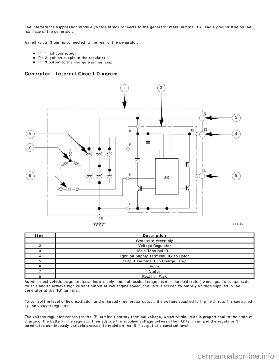
Generator - Internal Circuit Diagram
As with most vehicle ac generators, there is only minimal residual magnet ism in the field (rotor) windings. To compensate
for this and to achieve high current outp ut at low engine speed, the field is excited by battery voltage supplied to the
generator at the 'IG' terminal.
To control the level of field excitation and ultimately, generator output, the voltag e supplied to the field (rotor) is controlled
by the voltage regulator.
The voltage regulator senses (at the 'B' terminal) battery terminal voltage, which within limits is proportional to the state o f
charge of the battery. The regulator then adjusts the supplied voltage between the 'IG' terminal and the regulator 'F'
terminal (a continuously variable process) to maintain the 'B+' output at a constant level.
ItemDescription
1Generator Assembly
2Voltage Regulator
3Main Terminal 'B+'
4Ignition Supply Terminal 'IG' to Rotor
5Output Terminal L to Charge Lamp
6Rotor
7Stator
8Rectifier Pack
Page 1887 of 2490
Generator and Regulator - Generator
Diagnosis and Testing
Refer to PDU User Guide
Refer to the PDU User Manual for detailed instructions on testing the charging circuit.
When diagnosing the charging ci rcuit, the PDU indicates only whether the generator is charging or not charging. The reason
for this is that the PDU cannot handle the potential full charging current and that the voltage control circuits are located
within the generator assembly, making th em inaccessible by the PDU directly.
It is possible that the battery has failed. In this case, the voltage output at the generator could be correct, but the voltage
at the battery terminals, and therefore the rest of the vehicl e system, will be adversely affected by the faulty battery.
The same result is given by the PDU if the battery is faulty (generator not faulty), wiring fault (damaged or severe corrosion
at the terminals) or if th e generator is at fault.
Inspection and Verification
The following manual tests help to pinpoint which component is at fault.
Testing the Battery Circuit
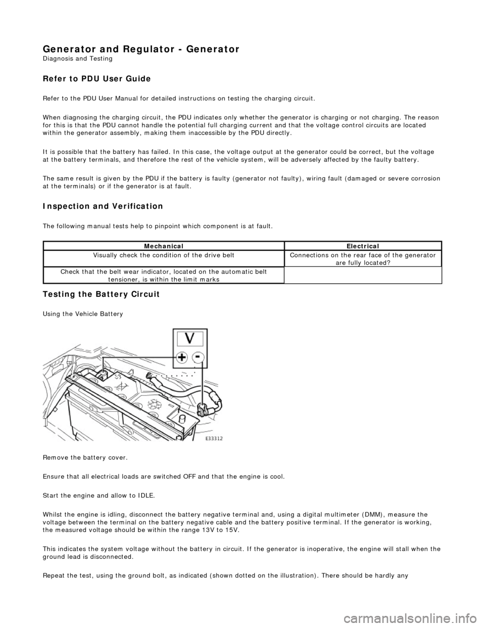
Using the Vehicle Battery
Remove the battery cover.
Ensure that all electrical loads are swit ched OFF and that the engine is cool.
Start the engine and allow to IDLE.
Whilst the engine is idling, disconnect the battery negative terminal and, using a digital multimeter (DMM), measure the
voltage between the terminal on the batter y negative cable and the battery positive terminal. If the generator is working,
the measured voltage should be within the range 13V to 15V.
This indicates the system voltage without the battery in circuit. If the generator is inoperative, the engine will stall when t he
ground lead is disconnected.
Repeat the test, using the ground bolt, as indicated (shown dotted on the illustration). There should be hardly any
MechanicalElectrical
Visually check the condition of the drive beltConnections on the rear face of the generator
are fully located?
Check that the belt we ar indicator, located on the automatic belt
tensioner, is within the limit marks
Page 1889 of 2490
CAUTION: The engine must not be running when multiplugs are connected or disconnected.
Check that the main B+ terminal is clean and tight.
Check that the IG terminal is clean and ma king good contact; if this connection is faulty, the generator will never function
correctly.
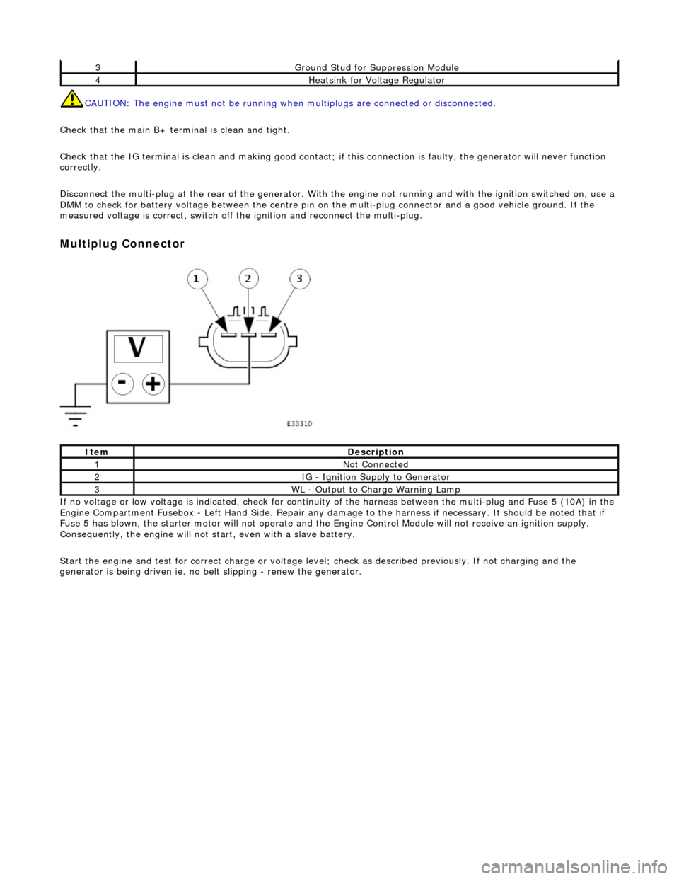
Disconnect the multi-plug at th e rear of the generator. With the engine not running and with the ignition switched on, use a
DMM to check for battery voltage between the centre pin on the multi-plug connector and a good vehicle ground. If the
measured voltage is correct, switch off the ignition and reconnect the multi-plug.
Multiplug Connector
If no voltage or low voltage is indicated, check for continuity of the harness between the multi-plug and Fuse 5 (10A) in the
Engine Compartment Fusebox - Left Hand Si de. Repair any damage to the harness if necessary. It should be noted that if
Fuse 5 has blown, the starter motor will not operate and the Engine Control Module will not receive an ignition supply.
Consequently, the engine will not st art, even with a slave battery.
Start the engine and test for correct ch arge or voltage level; check as described previously. If not charging and the
generator is being driven ie. no be lt slipping - renew the generator.
3Ground Stud for Suppression Module
4Heatsink for Voltage Regulator
ItemDescription
1Not Connected
2IG - Ignition Supply to Generator
3WL - Output to Charge Warning Lamp
Page 1890 of 2490
Generator and Regulator - Generator4.0L NA V8 - AJ27/3.2L NA V8 - AJ26
Removal and Installation
Removal
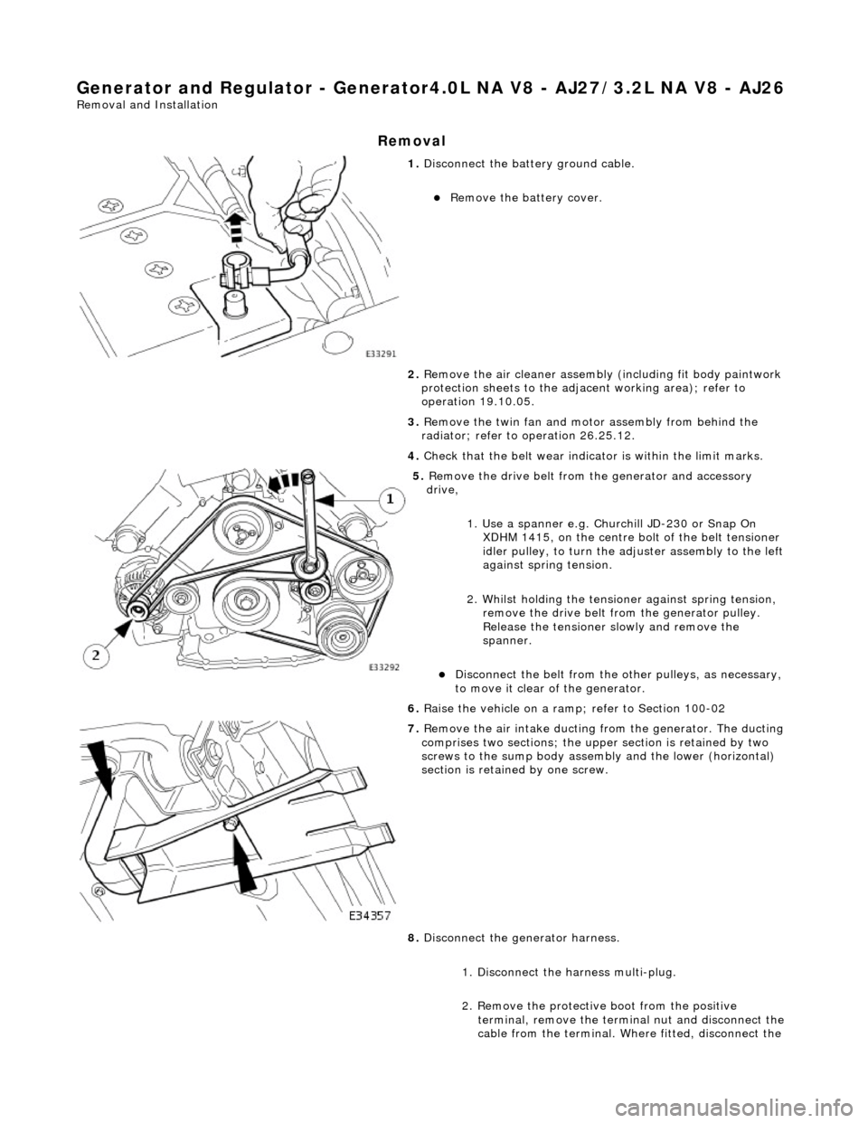
1. Disconnect the batt ery ground cable.
Remove the battery cover.
2. Remove the air cleaner assembly (including fit body paintwork
protection sheets to the adja cent working area); refer to
operation 19.10.05.
3. Remove the twin fan and moto r assembly from behind the
radiator; refer to operation 26.25.12.
4. Check that the belt wear indicator is within the limit marks.
5. Remove the drive belt from the generator and accessory
drive,
1. Use a spanner e.g. Churchill JD-230 or Snap On XDHM 1415, on the centre bo lt of the belt tensioner
idler pulley, to turn the adju ster assembly to the left
against spring tension.
2. Whilst holding the tensioner against spring tension, remove the drive belt from the generator pulley.
Release the tensioner sl owly and remove the
spanner.
Disconnect the belt from the ot her pulleys, as necessary,
to move it clear of the generator.
6. Raise the vehicle on a ramp; refer to Section 100-02
7. Remove the air intake ducting fr om the generator. The ducting
comprises two sections; the upper section is retained by two
screws to the sump body assembly and the lower (horizontal)
section is retained by one screw.
8. Disconnect the generator harness.
1. Disconnect the harness multi-plug.
2. Remove the protective boot from the positive
terminal, remove the termin al nut and disconnect the
cable from the terminal. Where fitted, disconnect the
Page 1893 of 2490
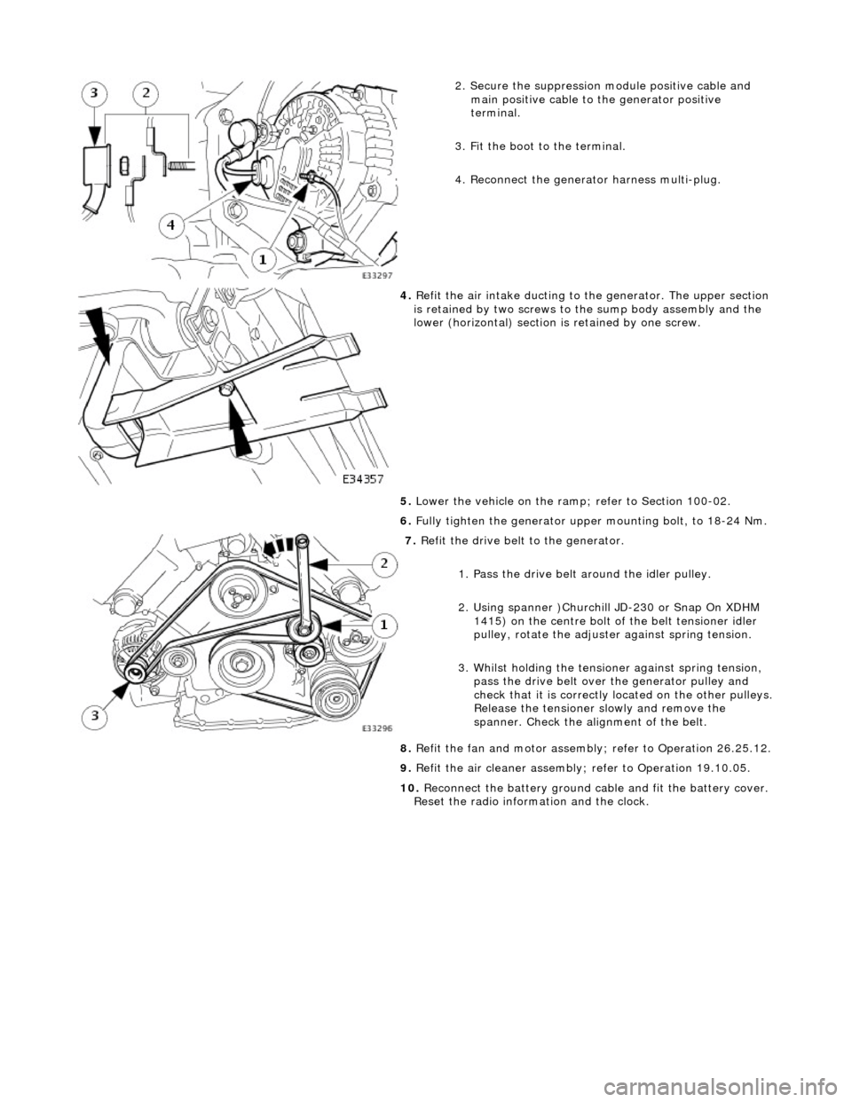
2. Secure the suppression module positive cable and
main positive cable to the generator positive
terminal.
3. Fit the boot to the terminal.
4. Reconnect the generator harness multi-plug.
4. Refit the air intake ducting to the generator. The upper section
is retained by two screws to the sump body assembly and the
lower (horizontal) section is retained by one screw.
5. Lower the vehicle on the ramp ; refer to Section 100-02.
6. Fully tighten the generator upper mounting bolt, to 18-24 Nm.
7. Refit the drive belt to the generator.
1. Pass the drive belt around the idler pulley.
2. Using spanner )Churchill JD-230 or Snap On XDHM 1415) on the centre bolt of the belt tensioner idler
pulley, rotate the adjuster against spring tension.
3. Whilst holding the tensioner against spring tension, pass the drive belt over the generator pulley and
check that it is correctly located on the other pulleys.
Release the tensioner slowly and remove the
spanner. Check the alignment of the belt.
8. Refit the fan and motor assembly ; refer to Operation 26.25.12.
9. Refit the air cleaner assembly; refer to Operation 19.10.05.
10. Reconnect the battery ground cable and fit the battery cover.
Reset the radio inform ation and the clock.
Page 1894 of 2490
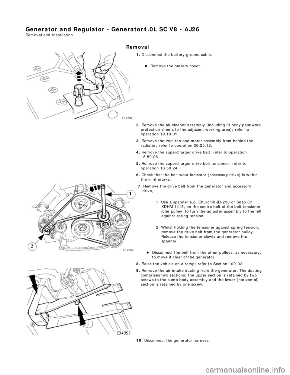
Generator and Regulator - Generator4.0L SC V8 - AJ26
Removal and Installation
Removal
1. Disconnect the batt ery ground cable.
Remove the battery cover.
2. Remove the air cleaner assembly (including fit body paintwork
protection sheets to the adja cent working area); refer to
operation 19.10.05.
3. Remove the twin fan and moto r assembly from behind the
radiator; refer to operation 26.25.12.
4. Remove the supercharger drive belt; refer to operation
18.50.08.
5. Remove the supercharger driv e belt tensioner; refer to
operation 18.50.24.
6. Check that the belt wear indica tor (accessory drive) is within
the limit marks.
7. Remove the drive belt from the generator and accessory
drive,
1. Use a spanner e.g. Churchill JD-230 or Snap On XDHM 1415, on the centre bo lt of the belt tensioner
idler pulley, to turn the adju ster assembly to the left
against spring tension.
2. Whilst holding the tensioner against spring tension, remove the drive belt from the generator pulley.
Release the tensioner sl owly and remove the
spanner.
Disconnect the belt from the ot her pulleys, as necessary,
to move it clear of the generator.
8. Raise the vehicle on a ramp; refer to Section 100-02
9. Remove the air intake ducting fr om the generator. The ducting
comprises two sections; the upper section is retained by two
screws to the sump body assembly and the lower (horizontal)
section is retained by one screw.
10. Disconnect the generator harness.
Page 1898 of 2490
1415) on the centre bolt of the belt tensioner idler
pulley, rotate the adjuster against spring tension.
3. Whilst holding the tensioner against spring tension, pass the drive belt over the generator pulley and
check that it is correctly located on the other pulleys.
Release the tensioner slowly and remove the
spanner. Check the alignment of the belt.
9. Fit the supercharger drive belt tensioner; refer to operation
18.50.24.
10. Fit the supercharger drive belt ; refer to operation 18.50.08.
11. Refit the fan and motor asse mbly; refer to Operation
26.25.12.
12. Refit the air cleaner assembly; refer to Operation 19.10.05.
13. Reconnect the battery ground cable and fit the battery cover.
Reset the radio inform ation and the clock.
Page 1899 of 2490
Generator and Regulator - Voltage Regulator
Removal and Installation
Removal
1. Disconnect the batt ery ground cable.
Remove the battery cover.
2. Remove the generator from the vehicle. Refer to Operation
86.10.02.
3. Remove the nut from the main terminal and remove the
insulator.
4. Remove the ground tag.
1. Remove the nut which secures the ground tag.
2. Remove the screw which secures the ground tag and remove the tag.
5. Remove the two remaining nuts which secure th e rear cover
and remove the cover.