1998 JAGUAR X308 oil
[x] Cancel search: oilPage 461 of 2490

sus
pension components
and for damaged coil springs in the front suspension.
as necessary. For addi tional information,
REF
ER to Section 204
-0
2 Rear Suspension
. I
NSTALL new front suspension components
as necessary. For addi tional information,
REFER to Section 204
-01
Front Suspension
.
Chec
k the rear suspension
for loose or worn
suspension components.
TIGHTE
N or INSTALL new components as
necessary. For additi onal information,
REFER to Section 204
-0
2 Rear Suspension
.
Incorre
ct underbody
alignment.
CHECK
underbody alignment. For additional
information,
REFER to Section 502
-00
Uni
-Body, Subframe and M
ounting System
.
Poor r
eturnability of the
steering
Lower steeri
ng column
interference.
CHECK
the steering co
lumn is free from
interference from the en gine harness, sound
proofing or the floor covering.
Incorrect
tire pressure.
CHECK
and ADJUST the tire pressure. For
additional information,
REFER to Section 204
-0
4 Wheels and Tires
.
Incorrect
tire size or type.
IN
STALL a new tire as necessary. For
additional information,
REFER to Section 204
-0
4 Wheels and Tires
.
Steeri
ng column upper
shroud fouling on the steering wheel.
CHECK
steering column upper shroud for
fouling. ADJUST as necessary.
Steeri
ng column universal
joints binding.
IN
STALL a new steering column. For
additional information,
REFER to Section 211
-0
4 Steering Column
.
Steeri
ng column shaft floor
seal binding.
CHE
CK the steering column shaft floor seal
for correct fitm ent and REFIT as necessary.
Steeri
ng column shaft floor
seal may be torn.
IN
STALL a new steering column shaft floor
seal as necessary.
Bin
ding or damaged tie-
rods.
CHECK
tie-rod end for excessive wear or
tightness in ball joint. INSTALL a new tie- rod end. For additional information,
REFER to Section 211
-0
3 Steering Linkage
.
D
amaged or worn front
suspension components.
I
NSTALL new front suspension components
as necessary. For addi tional information,
REFER to Section 204
-01
Front Suspension
.
Incorre
ct toe adjustment.
AD
JUST as necessary. For additional
information,
REFER to Section 204
-00
Suspension
Sy
stem
- General
Information
.
Excessive steeri
ng efforts
required during low speed
manoeuvring and/or during parking manoeuvres
Low power steer
ing fluid.
CHE
CK steering system
for signs of steering
fluid loss.
BLEE
D the power steering system. For
additional information,
REFER to Section 211
-0
0 Steering System
- General Informati
on
.
Damaged accessory driv
e
belt tensioner.
INST
ALL a new accessory drive belt
tensioner.
Hose or cooler li
ne
restriction.
CHECK
hose or cooler lines for correct
routing.
INST
ALL a new hose as necessary.
Fl
uid aeration.
BLEE
D the system. For additional
information,
REFER to Power Steering System Bleeding
in t
his section.
Steeri
ng transducer not
closed - no feed voltage.
CHECK
the steering transducer circuit. For
additional information, REFER to the wiring diagrams.
Carry ou
t the electrical checks and tests.
For additional information, REFER to the
Electrical Checks and Tests in this section.
Steeri
ng transducer not
closed - cable fault.
CHECK
the steering transducer circuit. For
additional information, REFER to the wiring diagrams.
Carry ou
t the electrical checks and tests.
Page 520 of 2490

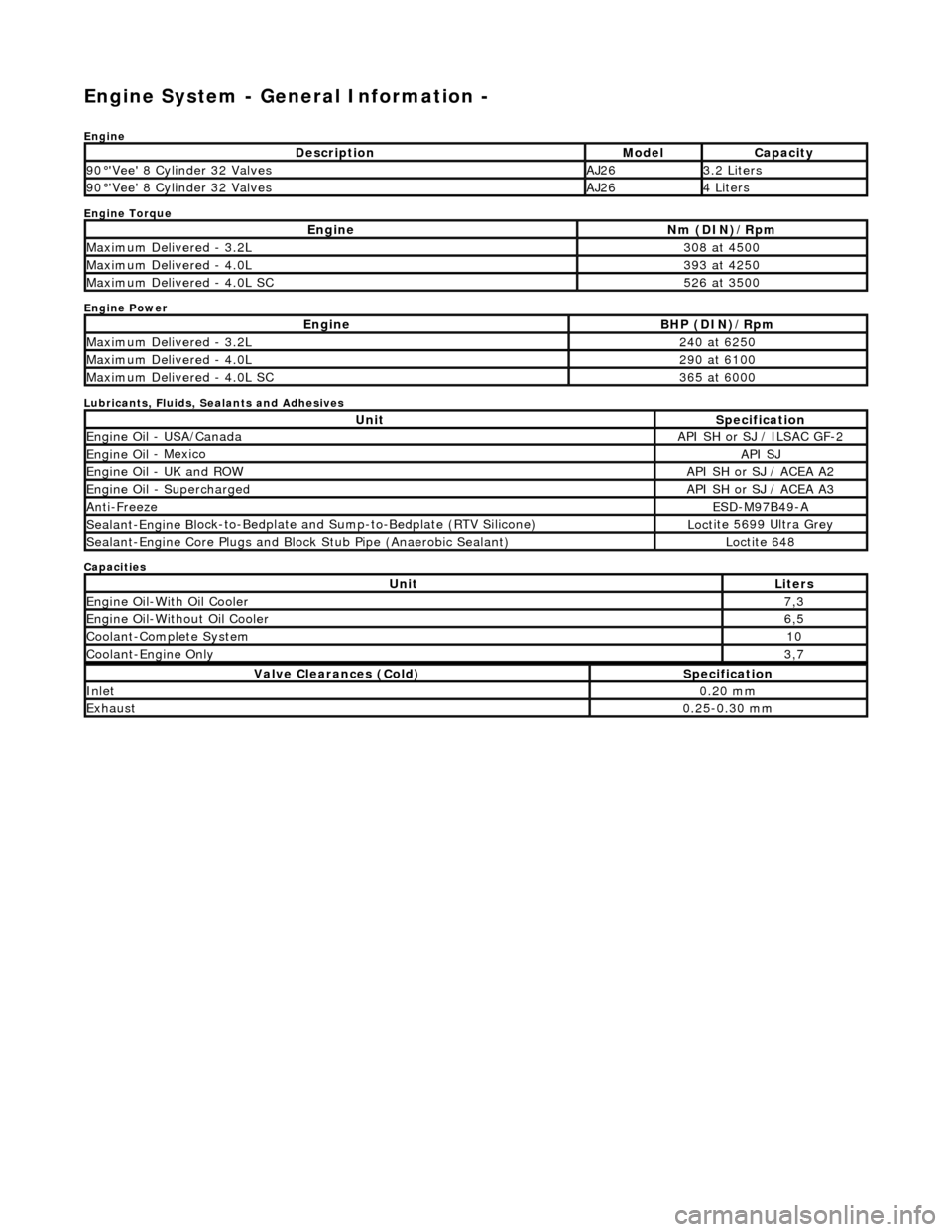
Engine System - General Inform
ation -
Eng
ine
Engine Torque
Engine Power
Lubricants, Fluids, Sealants and Adhesives
Capacities
Descr
iption
Mode
l
Capaci
ty
90
°'Ve
e' 8 Cylinder 32 Valves
AJ263.
2 L
iters
90
°'Ve
e' 8 Cylinder 32 Valves
AJ264 Li
te
rs
EngineNm (D
I
N)/Rpm
M
a
ximum Delivered - 3.2L
3
08 at
4500
M
a
ximum Delivered - 4.0L
3
93 at
4250
M
a
ximum Delivered - 4.0L SC
5
26 at
3500
EngineBH
P (D
IN)/Rpm
M
a
ximum Delivered - 3.2L
2
40 at
6250
M
a
ximum Delivered - 4.0L
2
90 at
6100
M
a
ximum Delivered - 4.0L SC
3
65 at
6000
UnitS
p
ecification
Engine Oil
-
USA/Canada
API SH or SJ
/ ILSAC G
F-2
Engine
Oil
- Mexico
API SJ
Engine
Oil
- UK and ROW
API SH or SJ
/ ACEA A2
Engine Oil -
Supercharged
API SH or SJ
/ ACEA A3
Anti-Freez
e
ESD-M97B
49
-A
Sealant-Engine B
l
ock-to-Bedplate an
d Sump-to-Bedplate (RTV Silicone)
Loct
ite 5699 Ultra Grey
Sealant-Engine
C
ore Plugs and Bloc
k Stub Pipe (Anaerobic Sealant)
Loctite 648
UnitLit
ers
Engine
Oil-W
ith Oil Cooler
7,
3
Engine Oil-W i
thout Oil Cooler
6,
5
Cool ant
-Complete System
10
Coo
lan
t-Engine Only
3,
7
Val v
e Clearances (Cold)
S
p
ecification
Inlet0.
20
mm
Exhaus
t0.25
-0.30 mm
Page 521 of 2490

Engine System - General Infor
mation - Engine
Description an
d Operation
The AJ26 power unit is available in 3.2 L and 4.0 L versions, and comprises:
An eight cylinder 9
0 degree 'V' config
uration liquid cooled aluminium cylinder block incorporating 'Nikasil' plated
cylinder bores.
Pi
stons of open-ended skirt design, with
two compression and one oil control ring.
Two al
uminium cylinder heads, each
incorporating two camshafts.
F
our valves per cylinder.
Al
uminium valve lifters and top mounted shims.
Vari
able valve timing (VVT) of the inlet camshafts (4.0 L normally aspirated only).
Camshaft
covers manufactured from Vinylester.
Al
uminium timing cover which accommodat
es the crankshaft front oil seal.
Sin
gle row primary and secondary chains dr
ive the camshafts of each cylinder bank.
An alu
minium bed pl
ate, incorporating iron main bearing supports, which accomm odate the oil pump pick-up,
Page 522 of 2490

diverter val
ve (if fitted) and oil filter.
Main
bearings
which are grooved in the upper positions and plain in
the lower positions. They are manufactured from
aluminium / tin material.
A c
rankshaft with under
cuts and rolled fillets for extra strength.
Fracture
-split connecting rods in sintered-forged steel.
Brackets
bolted to the front of
the cylinder
block are used to mo unt all accessories.
A sin
gle, seven ribbed vee belt
drives the accessories.
An au
tomatic belt tensioner for the front accessory drive,
incorporating a wear indicator.
An advanced en
gine management system inco
rporating electronic throttle control.
The un
it meets the requirements of the CARB OBDII USA legislation.
Ancillary Systems
The an
ci
llary systems, driven by the engine, each have a
detailed Description and Operation along with Diagnostic
Procedures, and Removal and Installation instructions ; refer to the following sections of this manual:
Power Steeri
ng Pump - Section 211-02
Ai
r Conditioning Compressor - Sectio
n 412-03
Engine
C
ooling Pump - Section 303-03
Generator
- Sectio
n 414-02
The drive belt, idler pulley and automatic tensioner are described in Section 303-05.
The engine starting system is described in Section 303-06.
En
gine Management and Emission Control System
Engine Control Modu
le (ECM)
Engine
management and exhaust emissions are controlled by the ECM, which has the
following main functions:
Fu
el injection
Idle
s
peed
Ignition Ev
aporative loss system
Engine
cooling fans Clim
ate control compressor clutch demand
The microprocessor within the ECM receiv es signals from various sensors and other modules and uses a pre-determined
program to compute engine management functions.
Adaptive functions are incorporated in the ECM to cater for co ntinuous adjustments to its computations to suit prevailing
conditions. Because the system also controls emissions to suit all modes, neither CO levels nor idle speed require service
attention or adjustment, except if an error should occur.
On Board Diagnostics are controlled by the ECM with the continuous monitoring of incoming signals and the subsequent
verification against what the module expects to 'see'. Should a si gnal be incorrect or missing, the ECM will substitute a fixed
value to provide the 'limp home mode' and alert the driver of the problem. Fixed values may be adopted for:
Transmission oil
temperature
Mechanica
l
guar
d position
Throttle blade angle Camshaft position
Inta
k
e air temperature
Diagnostic trouble codes (DTC), including OBD II codes, are stored in the ECM memo ry and can be read by an appropriate
retrieval tool.
Should either the ECM or TCM fa il, ensure that the control housing cooling fan is operating correctly. Failure of the cooling
fan MUST be rectified before renewing a control module and details of a fa n failure should accompany a returned control
module.
Page 528 of 2490

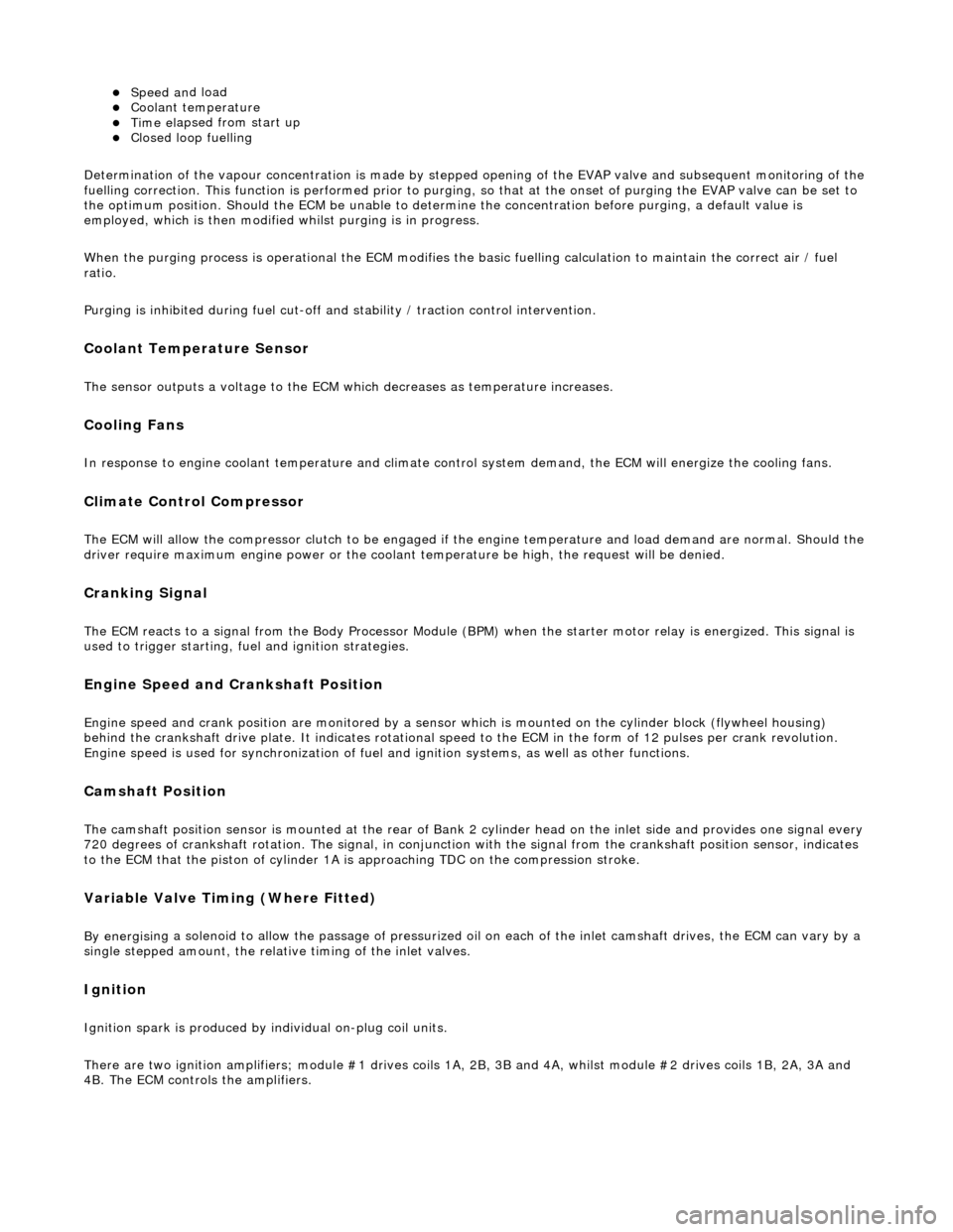
Speed an
d load
Coo
l
ant temperature
Ti
me el
apsed from start up
Cl
osed l
oop fuelling
Determination of the vapour concentration is made by stepped opening of the EVAP valve and subsequent monitoring of the
fuelling correction. This function is performed prior to purging, so that at the onse t of purging the EVAP valve can be set to
the optimum position. Should the ECM be unable to determine the concentration before purging, a default value is
employed, which is then modified whilst purging is in progress.
When the purging process is operational th e ECM modifies the basic fuelling calculation to maintain the correct air / fuel
ratio.
Purging is inhibited during fuel cut-off and stability / traction control intervention.
Coolant Temperature Sen
sor
Th
e
sensor outputs a voltage to the ECM which decreases as temperature increases.
Cooling Fans
In response to engi
ne coolant temperat
u
re and climate control system demand, the ECM will energize the cooling fans.
Climate Control Compressor
The E
C
M will allow the compressor clutch to be engaged if th
e engine temperature and load demand are normal. Should the
driver require maximum engine powe r or the coolant temperature be high, the request will be denied.
Cranking Signal
The ECM reacts to a signal fr
om th
e Body Processor Module (BPM) when the starter motor relay is energi
zed. This signal is
used to trigger starting, fu el and ignition strategies.
Engine Speed and Cranksh
aft Position
Engine
speed and cran
k position are moni
tored by a sensor which is mounted on the cylinder block (flywheel housing)
behind the crankshaft drive plat e. It indicates rotational speed to the ECM in the form of 12 pulses per crank revolution.
Engine speed is used for synchronization of fuel an d ignition systems, as well as other functions.
Camshaft Position
The ca
mshaft position sensor is mounted at
the rear of Bank 2 cylinder head on the inlet side and provides one signal every
720 degrees of crankshaft rotation. The signal, in conjunction with the signal from the crankshaft position sensor, indicates
to the ECM that the piston of cylinder 1A is approaching TDC on the compression stroke.
Variable Valve
Timing (Where Fitted)
By energi
si
ng a solenoid to allow the pass
age of pressurized oil on each of the inle t camshaft drives, the ECM can vary by a
single stepped amount, the relati ve timing of the inlet valves.
Ign
ition
Ignit
i
on spark is produced by
individual on-plug coil units.
There are two ignition amplifiers; module #1 drives coils 1A, 2B, 3B and 4A, whilst module #2 drives coils 1B, 2A, 3A and
4B. The ECM controls the amplifiers.
Page 530 of 2490

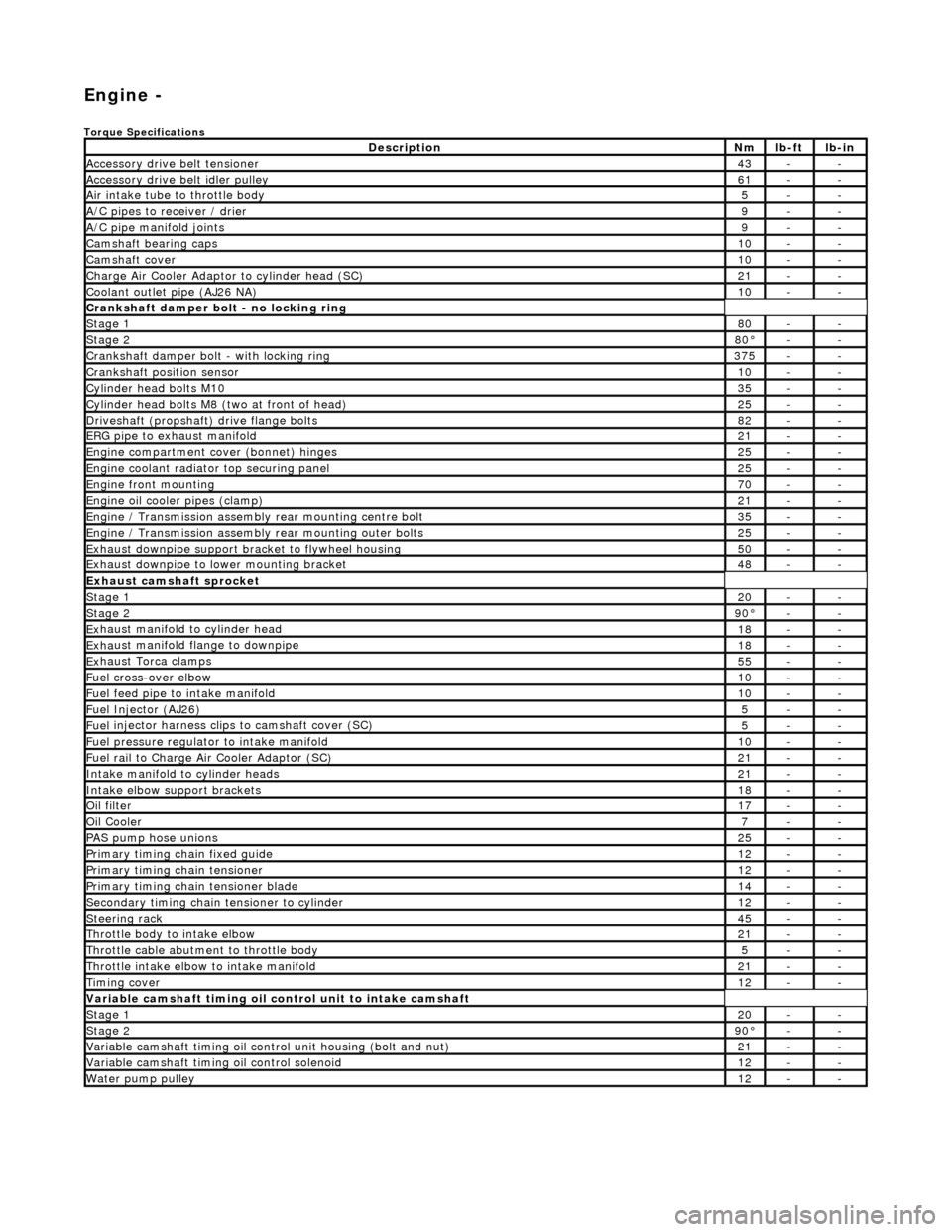
Engi
ne -
Torqu
e Specifications
De
s
cription
Nmlb
-
ft
lb
-
in
A
ccessory
drive belt tensioner
43--
A
ccessory
drive belt idler pulley
61--
Air in
ta
ke tube to throttle body
5--
A/C
pipes t
o receiver / drier
9--
A/C pipe m
anifold joints
9--
Camsh
aft bearin
g caps10--
Ca
msh
aft cove
r10--
Ch
arge Air Co
oler Adaptor to cylinder head (SC)
21--
Co
olan
t outlet pipe (AJ26 NA)
10--
Cran
kshaft damper bolt - no lockin
g ring
St
ag
e 1
80--
Stag
e 2
80°--
C
r
ankshaft damper bolt - with locking ring
37
5--
Cra
nkshaft position sensor
10--
Cy
li
nder head bolts M10
35--
Cy
lin
der head bolts M8 (two at front of head)
25--
Driv
es
haft (propshaft) drive flan
ge bo
l
ts
82--
ERG p
i
pe to exhaust manifold
21--
Engi
ne compartment cover (bonnet) hinges
25--
En
gine
coolant radiator top securing panel
25--
E
ng
ine front mounting
70--
En
gine
oil cooler pipes (clamp)
21--
En
gi
ne / Transmission assembly rear mounting centre bolt
35--
En
gi
ne / Transmission assembly rear mounting outer bolts
25--
Ex
ha
ust downpipe support bracket to flywheel housing
50--
Ex
ha
ust downpipe to lower mounting bracket
48--
E
x
haust camshaft sprocket
St
age 120--
Stage 290 °--
Ex
haust manifold to cylinder head
18--
Ex
ha
ust manifold flange to downpipe
18--
E
x
haust Torca clamps
55--
Fuel cross-over elbo
w
10--
Fu
el f
eed pipe to intake manifold
10--
Fuel
Injector (AJ
26)
5--
Fuel
injector ha
rness clips to camshaft cover (SC)
5--
Fu
el p
ressure re
gu
l
ator to intake manifold
10--
F
u
el rail to Char
ge
A
ir Cooler Adaptor (SC)
21--
In
ta
ke manifold to cylinder heads
21--
Inta
ke elbow support brackets
18--
Oil f
i
lter
17--
Oil C
o
oler
7--
P
AS pu
mp hose unions
25--
P
r
imary timing chain fixed guide
12--
P
r
imary timing chain tensioner
12--
Pr
imary timing chain tensioner blade
14--
S
e
condary timing chain tensioner to cylinder
12--
S
t
eerin
g ra
ck45--
Thro
ttle body to intake elbow
21--
Th
ro
ttle cable abutment to throttle body
5--
Th
ro
ttle intake elbow to intake manifold
21--
Ti
mi
ng cover
12--
Variable camshaft t
i
ming oil control unit to intake camshaft
St
ag
e 1
20--
St
ag
e 2
90
°--
Var
iable camshaft timing oil control unit housing (bolt and nut)
21--
Va
ria
ble camshaft timi
ng oil control solenoid
12--
Wa
ter pump pulley
12--
Page 531 of 2490

En
gine - Engine
D
iagnosis and Testing
Sym
ptom Chart
Sy
mptom Chart
Pinp
oint test A: P1392 (P1397)
VVT solenoid circuit low input
S
pecial Tool(s)
D
igital multimeter
Generi
c scan tool
Sy
mptom
Possib
le Sources
Acti
on
D
TC P1392 VVT solenoid A circuit low input
So
lenoid coil open circuit
Harness open circuit or blown fuse
Connector pins(s) bent , loose or corroded
*
*
*
GO to
P
inpoint Test A
*
D
TC P1397 VVT solenoid B circuit low input
So
lenoid coil open circuit
Harness open circuit or blown fuse
Connector pins(s) bent , loose or corroded
*
*
*
GO to
P
inpoint Test A
*
D
TC P1393 VVT solenoid A circuit high input
So
lenoid coil short circuit
Harness short circuit
Connector pins(s) bent , loose or corroded
*
*
*
GO to
P
inpoint Test B
*
D
TC P1398 VVT solenoid B circuit high input
So
lenoid coil short circuit
Harness short circuit
Connector pins(s) bent , loose or corroded
*
*
*
GO to
P
inpoint Test B
*
D
TC P1396 VVT solenoid B malfunction
O
il pressure failure
VVT solenoid sticking
Connector pins(s) bent , loose or corroded
Crankshaft position sensor failure
ECM failure
*
*
*
*
*
GO to
P
inpoint Test C
*
P
INPOINT TEST A : P1392 (P1397) VVT SOLENOID CIRCUIT LOW INPUT
•
NOTE: References in brac
kets are for Bank B (2)
T
EST CONDITIONS
D
ETAILS/RESULTS/ACTIONS
A1
: RETRIEVE DTCS
•
NOTE: Battery and or ECM disconnection prior to scanning wi
ll erase all data, ensure that the correct DTC is present.
Page 532 of 2490

Connect
the scan tool
1
Have the DTC(s) and fr
eeze f
rame data been recorded?
Yes GO to A2
A2: CH
ECK FUSE / RELAY
Check that fuse F
12 i
s good
and that EMS control relay is
energized
1
OK ?
Yes GO to A3
No Rectify as required
A3: CH
ECK VVT COIL RESISTANCE