1998 JAGUAR X308 module
[x] Cancel search: modulePage 522 of 2490

diverter val
ve (if fitted) and oil filter.
Main
bearings
which are grooved in the upper positions and plain in
the lower positions. They are manufactured from
aluminium / tin material.
A c
rankshaft with under
cuts and rolled fillets for extra strength.
Fracture
-split connecting rods in sintered-forged steel.
Brackets
bolted to the front of
the cylinder
block are used to mo unt all accessories.
A sin
gle, seven ribbed vee belt
drives the accessories.
An au
tomatic belt tensioner for the front accessory drive,
incorporating a wear indicator.
An advanced en
gine management system inco
rporating electronic throttle control.
The un
it meets the requirements of the CARB OBDII USA legislation.
Ancillary Systems
The an
ci
llary systems, driven by the engine, each have a
detailed Description and Operation along with Diagnostic
Procedures, and Removal and Installation instructions ; refer to the following sections of this manual:
Power Steeri
ng Pump - Section 211-02
Ai
r Conditioning Compressor - Sectio
n 412-03
Engine
C
ooling Pump - Section 303-03
Generator
- Sectio
n 414-02
The drive belt, idler pulley and automatic tensioner are described in Section 303-05.
The engine starting system is described in Section 303-06.
En
gine Management and Emission Control System
Engine Control Modu
le (ECM)
Engine
management and exhaust emissions are controlled by the ECM, which has the
following main functions:
Fu
el injection
Idle
s
peed
Ignition Ev
aporative loss system
Engine
cooling fans Clim
ate control compressor clutch demand
The microprocessor within the ECM receiv es signals from various sensors and other modules and uses a pre-determined
program to compute engine management functions.
Adaptive functions are incorporated in the ECM to cater for co ntinuous adjustments to its computations to suit prevailing
conditions. Because the system also controls emissions to suit all modes, neither CO levels nor idle speed require service
attention or adjustment, except if an error should occur.
On Board Diagnostics are controlled by the ECM with the continuous monitoring of incoming signals and the subsequent
verification against what the module expects to 'see'. Should a si gnal be incorrect or missing, the ECM will substitute a fixed
value to provide the 'limp home mode' and alert the driver of the problem. Fixed values may be adopted for:
Transmission oil
temperature
Mechanica
l
guar
d position
Throttle blade angle Camshaft position
Inta
k
e air temperature
Diagnostic trouble codes (DTC), including OBD II codes, are stored in the ECM memo ry and can be read by an appropriate
retrieval tool.
Should either the ECM or TCM fa il, ensure that the control housing cooling fan is operating correctly. Failure of the cooling
fan MUST be rectified before renewing a control module and details of a fa n failure should accompany a returned control
module.
Page 528 of 2490

Speed an
d load
Coo
l
ant temperature
Ti
me el
apsed from start up
Cl
osed l
oop fuelling
Determination of the vapour concentration is made by stepped opening of the EVAP valve and subsequent monitoring of the
fuelling correction. This function is performed prior to purging, so that at the onse t of purging the EVAP valve can be set to
the optimum position. Should the ECM be unable to determine the concentration before purging, a default value is
employed, which is then modified whilst purging is in progress.
When the purging process is operational th e ECM modifies the basic fuelling calculation to maintain the correct air / fuel
ratio.
Purging is inhibited during fuel cut-off and stability / traction control intervention.
Coolant Temperature Sen
sor
Th
e
sensor outputs a voltage to the ECM which decreases as temperature increases.
Cooling Fans
In response to engi
ne coolant temperat
u
re and climate control system demand, the ECM will energize the cooling fans.
Climate Control Compressor
The E
C
M will allow the compressor clutch to be engaged if th
e engine temperature and load demand are normal. Should the
driver require maximum engine powe r or the coolant temperature be high, the request will be denied.
Cranking Signal
The ECM reacts to a signal fr
om th
e Body Processor Module (BPM) when the starter motor relay is energi
zed. This signal is
used to trigger starting, fu el and ignition strategies.
Engine Speed and Cranksh
aft Position
Engine
speed and cran
k position are moni
tored by a sensor which is mounted on the cylinder block (flywheel housing)
behind the crankshaft drive plat e. It indicates rotational speed to the ECM in the form of 12 pulses per crank revolution.
Engine speed is used for synchronization of fuel an d ignition systems, as well as other functions.
Camshaft Position
The ca
mshaft position sensor is mounted at
the rear of Bank 2 cylinder head on the inlet side and provides one signal every
720 degrees of crankshaft rotation. The signal, in conjunction with the signal from the crankshaft position sensor, indicates
to the ECM that the piston of cylinder 1A is approaching TDC on the compression stroke.
Variable Valve
Timing (Where Fitted)
By energi
si
ng a solenoid to allow the pass
age of pressurized oil on each of the inle t camshaft drives, the ECM can vary by a
single stepped amount, the relati ve timing of the inlet valves.
Ign
ition
Ignit
i
on spark is produced by
individual on-plug coil units.
There are two ignition amplifiers; module #1 drives coils 1A, 2B, 3B and 4A, whilst module #2 drives coils 1B, 2A, 3A and
4B. The ECM controls the amplifiers.
Page 906 of 2490

the pipes. Allow the oil to drain.
3. Remove the O-ring seals and fit blanking plugs to the
pipes and to the mating unions on the engine.
51. Lower the ramp.
52. Disconnect the generator suppres sion module (where fitted)
harness.
Disconnect the harness multi-plug and reposition the
harness from under the suppression module.
53. Disconnect the starter motor power cable, at the right hand
side engine compartment enclosure.
1. Disconnect the multi-plug, engine management harness to starter motor.
2. Reposition the protective boot from the starter motor
power stud.
3. Remove the nut and disc onnect the power cable.
Cut the tie strap which secures the power cable to the
enclosure and route the cable into the engine bay.
54. Disconnect the P.I. harness from the engine management
harness.
1. Release the bolt which secures the P.I. harness multi-plug to the engine management harness.
2. Disconnect the multi-plug.
3. Remove the nut which secures the engine management harness multi-plug to the mounting
bracket.
4. Reposition the multi-plug from the bracket.
55. Disconnect the transmission rota ry switch harness connector.
Reposition and disconnect the harness multi-plug.
Page 917 of 2490

WARNING: B
EFORE PROCEEDING, IT IS ESSENTIAL THAT
THE WARNING NOTES GIVEN IN SECTION 100-00 (UNDER
THE HEADING 'SAFETY PRECAUTION S') ARE READ AND UNDERSTOOD.
3.
Connect the vacuum hose to the purge valve.
30
.
Connect the fuel feed and return hoses.
R
emove the blanking plugs
from the mating pipes.
1. Connect the hoses at the Quick Fit connectors.
F
it the return hose into the feed hose clip.
31
.
Connect the starter motor power cable.
1. Reposition and connect the power cable to the power stud. Fit the securing nut to the stud.
2. Reposition the protective boot over the starter motor power stud.
3. Connect the harness connector, engine management harness to starter motor. Fit the connector to the
mounting bracket.
R
enew the tie strap which secures the power cable to the
right hand enclosure.
32
.
Connect the generator suppressi on module (where fitted)
harness.
Re
position the harn
ess under the suppression module and
connect the harness connector.
33. Connect the hoses to the power steering pump.
Page 930 of 2490

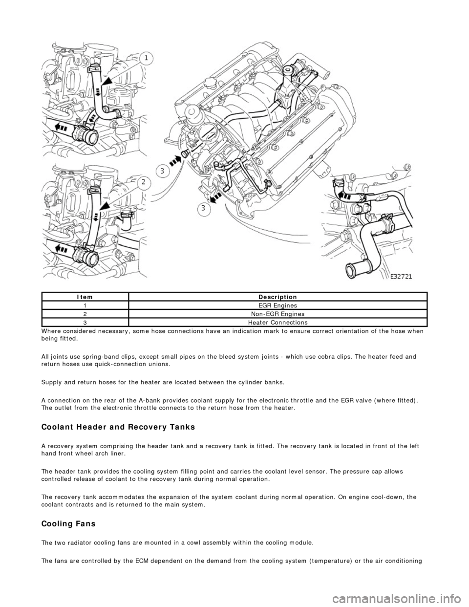
Whe r
e considered necessary, some hose conn
ections have an indication mark to ensure correct orientation of the hose when
being fitted.
All joints use spring-band clips, except small pipes on the bleed system joints - which use cobra clips. The heater feed and
return hoses use quick-connection unions.
Supply and return hoses for the heater are located between the cylinder banks.
A connection on the rear of the A-bank provides coolant supply for the electronic throttle and the EGR valve (where fitted).
The outlet from the electronic throttle connects to the return hose from the heater.
Cool
ant Header and Recovery Tanks
A recovery system comp
rising the header tank
and a recovery tank is fitted. The recove ry tank is located in front of the left
hand front wheel arch liner.
The header tank provides the cooling system filling point and carries the coolant level sensor. The pressure cap allows
controlled release of coolant to the re covery tank during normal operation.
The recovery tank accommodates the expansion of the system coolant during normal operation. On engine cool-down, the
coolant contracts and is returned to the main system.
Coo lin
g Fans
The two
rad
iator cooling fans are mounted in
a cowl assembly within the cooling module.
The fans are controlled by the ECM dependent on the demand fr om the cooling system (temperature) or the air conditioning
ItemDescrip
tion
1EGR
E
ngines
2Non
-
EGR Engines
3Hea
ter Connections
Page 931 of 2490

s
ystem (pressure).
Outputs from the ECM control the radiator fans control module, located behind the left hand side of the bumper, to operate
the fans in the series mode (slow), paralle l mode (Fast) or Off modes. Hysteresis in the temperature and pressure switching
values prevents 'hun ting' between modes.
Under hot operating conditions, the fans may continue to operat e for some time after the engine has been switched off, but
will stop automatically when the coolant te mperature has been sufficiently reduced.
Engine Coolant Temperature Sensor (ECT) and ECM
The engine coolant temperature (ECT) sensor is located in the coolant outlet pipe and reacts to engine coolant temperature
changes, providing an input to the Engine Control Module (ECM). The sensor has a negative te mperature coefficient so that
the sensor resistance decrea ses as temperature rises.
Temperature / Resistance Relationship Graph
T
emperature / Resistance
Relationship Table
Page 933 of 2490

ItemPar
t Number
De
scription
1—Lug
gage compartment fuse box
2—I
ntercooler pump relay
3—I
ntercooler pump
4—Electr
onic control module
Page 1015 of 2490

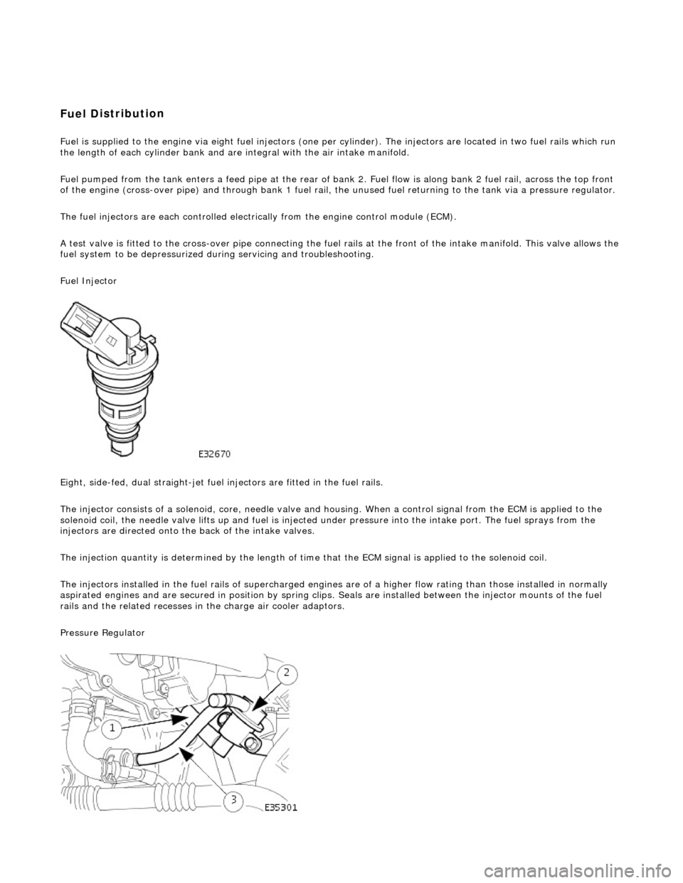
Fuel D
istribution
Fuel is supplied to th
e engine
via eight fuel injectors (one pe r cylinder). The injectors are located in two fuel rails which r un
the length of each cylinder bank and ar e integral with the air intake manifold.
Fuel pumped from the tank enters a feed pipe at the rear of bank 2. Fuel flow is along bank 2 fuel rail, across the top front
of the engine (cross-over pipe) and through bank 1 fuel rail, the unused fuel re turning to the tank via a pressure regulator.
The fuel injectors are each controlled electrically from the engine control module (ECM).
A test valve is fitted to the cross-over pipe connecting the fu el rails at the front of the intake manifold. This valve allows the
fuel system to be depr essurized during servicin g and troubleshooting.
Fuel Injector
Eight, side-fed, dual straight-jet fuel injectors are fi tted in the fuel rails.
The injector consists of a solenoid, core, needle valve and ho using. When a control signal from the ECM is applied to the
solenoid coil, the needle valve lifts up and fuel is injected under pressure into the intake port. The fuel sprays from the
injectors are directed onto the back of the intake valves.
The injection quantity is determined by the length of time that the ECM signal is applied to the solenoid coil.
The injectors installed in the fuel rails of supercharged engines are of a higher flow rating than those installed in normally
aspirated engines and are secured in position by spring clips. Seals are instal led between the injector mounts of the fuel
rails and the related re cesses in the charge air cooler adaptors.
Pressure Regulator