1998 JAGUAR X308 engine dtc
[x] Cancel search: engine dtcPage 1077 of 2490
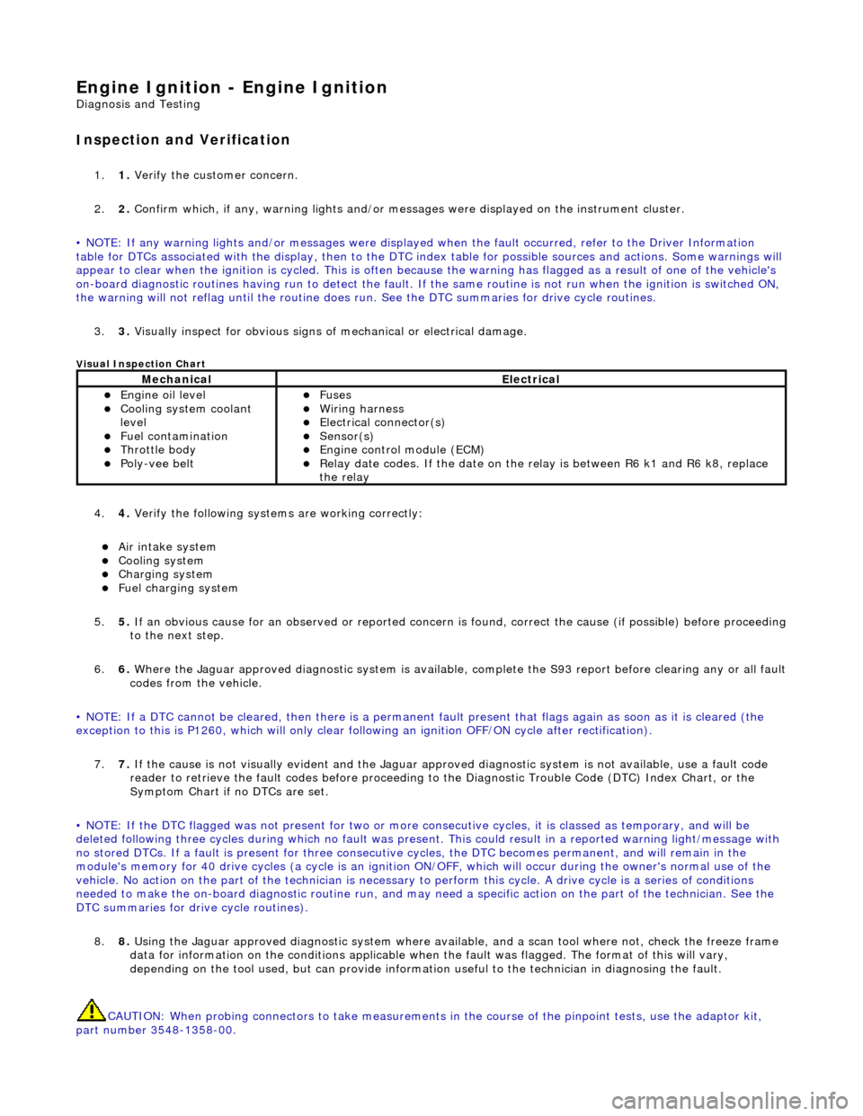
Engine Igni
tion -
Engine Ignition
D
iagnosis and Testing
I
nspection and Verification
1.
1. Veri
fy the customer concern.
2. 2. Confirm which, if any, warning li ghts and/or messages were displayed on the instrument cluster.
• NOTE: If any warning lights and/or me ssages were displayed when the fault occurred, refer to the Driver Information
table for DTCs associated with the display, then to the DTC index table for possible sources and actions. Some warnings will
appear to clear when the ignition is cycl ed. This is often because the warning has flagged as a resu lt of one of the vehicle's
on-board diagnostic routines having run to detect the fault. If the same routine is not run when the ignition is switched ON,
the warning will not reflag until the routine does run. See the DTC summaries for drive cycle routines.
3. 3. Visually inspect for obvious signs of mechanical or electrical damage.
V
isual Inspection Chart
4.
4. Veri
fy the following syst
ems are working correctly:
Air in
take system
Coo
ling system
Charging system
F
uel charging system
5. 5. If an obvious cause for an observed or reported concern is found, correct the cause (if possible) before proceeding
to the next step.
6. 6. Where the Jaguar approved diagnostic sy stem is available, complete the S93 report before clearing any or all fault
codes from the vehicle.
• NOTE: If a DTC cannot be cleared, then there is a permanent fault present that flag s again as soon as it is cleared (the
exception to this is P1260, which will only clear following an ignition OFF/ON cycle after rectification).
7. 7. If the cause is not visually evident and the Jaguar approv ed diagnostic system is not available, use a fault code
reader to retrieve the fault codes be fore proceeding to the Diagnostic Trou ble Code (DTC) Index Chart, or the
Symptom Chart if no DTCs are set.
• NOTE: If the DTC flagged was not present for two or more co nsecutive cycles, it is classed as temporary, and will be
deleted following three cycl es during which no fault was present. This could result in a reported wa rning light/message with
no stored DTCs. If a fault is present for three consecutive cycles, the DTC becomes permanent, and will remain in the
module's memory for 40 drive cycles (a cy cle is an ignition ON/OFF, which will occur during the owner's normal use of the
vehicle. No action on the part of the technician is necessary to perform this cycle. A drive cycle is a series of conditions
needed to make the on-board diagnostic ro utine run, and may need a specific action on the part of the technician. See the
DTC summaries for driv e cycle routines).
8. 8. Using the Jaguar approved diagnostic system where available, and a scan tool where not, check the freeze frame
data for information on the conditions applicable when the fault was flagged. The format of this will vary,
depending on the tool used, but can pr ovide information useful to the technician in diagnosing the fault.
CAUTION: When probing connectors to take measurements in the course of the pinpoint tests, use the adaptor kit,
part number 3548-1358-00.
MechanicalElectrical
Engi
ne oil level
Coo
ling system coolant
level
Fuel contamination
Throttle body Poly
-vee belt
F
uses
W
iring harness
E
lectrical connector(s)
Sens
or(s)
Engine
control module (ECM)
Relay date codes.
If the date on the relay is between R6 k1 and R6 k8, replace
the relay
Page 1079 of 2490
F
or evaporative emissions components,
REFER to: Evaporative Emissions
(30
3-13
Evaporative Emissions, Diagnosis and Testing).
For ECT sensor tests,
REFER to: Electronic Engine Controls
(30
3-14
Electronic Engine Co ntrols, Diagnosis and
Testing).
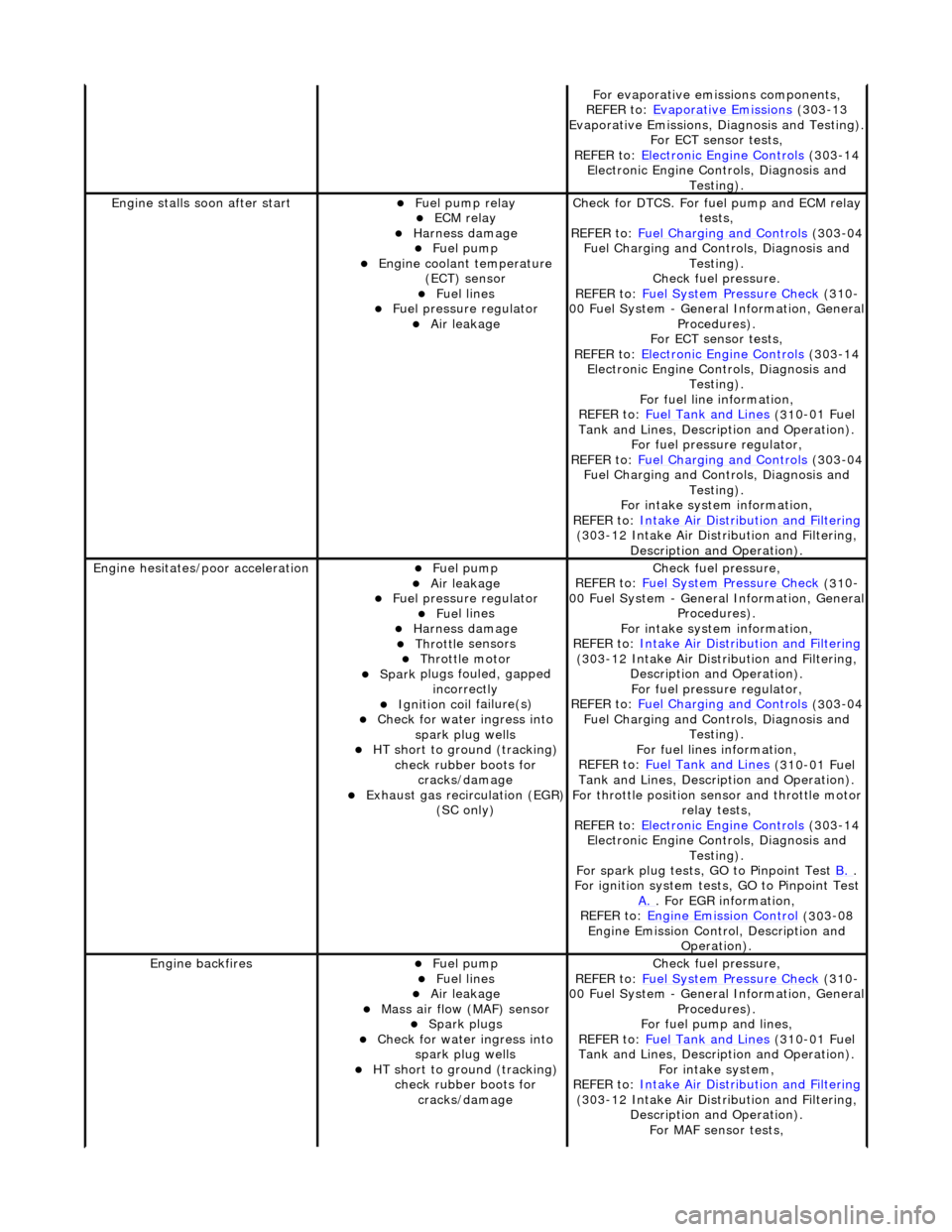
Engine stalls
soon after start
F
uel pump relay
ECM relay
Harness damage Fue
l pump
Engine coolan
t temperature
(ECT) sensor
Fue
l lines
F
uel pressure regulator
Air leakage
Check f
or DTCS. For fuel pump and ECM relay
tests,
REFER to: Fuel Charging and Controls
(30
3-04
Fuel Charging and Controls, Diagnosis and Testing).
Check fuel pressure.
REFER to: Fuel System Pressure Check
(31
0-
00 Fuel System - Genera l Information, General
Procedures).
For ECT sensor tests,
REFER to: Electronic Engine Controls
(30
3-14
Electronic Engine Co ntrols, Diagnosis and
Testing).
For fuel line information,
REFER to: Fuel Tank and Lines
(31
0-01 Fuel
Tank and Lines, Description and Operation).
For fuel pressure regulator,
REFER to: Fuel Charging and Controls
(30
3-04
Fuel Charging and Controls, Diagnosis and Testing).
For intake system information,
REFER to: Intake Air Distribution and Filtering
(30
3-12 Intake Air Distribution and Filtering,
Description and Operation).
Engine hesi
tates/poor acceleration
Fue
l pump
Air leakage
F
uel pressure regulator
Fue
l lines
Harness damage Throttl
e sensors
Throttl
e motor
Spark
plugs fouled, gapped
incorrectly
Ignition coil
failure(s)
Check f
or water ingress into
spark plug wells
HT sho
rt to ground (tracking)
check rubber boots for cracks/damage
Exhaus
t gas recirculation (EGR)
(SC only)
Chec
k fuel pressure,
REFER to: Fuel System Pressure Check
(31
0-
00 Fuel System - Genera l Information, General
Procedures).
For intake system information,
REFER to: Intake Air Distribution and Filtering
(30
3-12 Intake Air Distribution and Filtering,
Description and Operation). For fuel pressure regulator,
REFER to: Fuel Charging and Controls
(30
3-04
Fuel Charging and Controls, Diagnosis and Testing).
For fuel lines information,
REFER to: Fuel Tank and Lines
(31
0-01 Fuel
Tank and Lines, Description and Operation).
For throttle position se nsor and throttle motor
relay tests,
REFER to: Electronic Engine Controls
(30
3-14
Electronic Engine Co ntrols, Diagnosis and
Testing).
For spark plug tests, GO to Pinpoint Test B.
.
For ign
ition system tests, GO to Pinpoint Test
A.
. F
or EGR information,
REFER to: Engine Emission Control
(30
3-08
Engine Emission Cont rol, Description and
Operation).
Engine ba
ckfires
Fue
l pump
Fue
l lines
Air leakage
Mass ai
r flow (MAF) sensor
Spark plugs
Check f
or water ingress into
spark plug wells
HT sho
rt to ground (tracking)
check rubber boots for cracks/damage
Chec
k fuel pressure,
REFER to: Fuel System Pressure Check
(31
0-
00 Fuel System - Genera l Information, General
Procedures).
For fuel pump and lines,
REFER to: Fuel Tank and Lines
(31
0-01 Fuel
Tank and Lines, Description and Operation).
For intake system,
REFER to: Intake Air Distribution and Filtering
(30
3-12 Intake Air Distribution and Filtering,
Description and Operation). For MAF sensor tests,
Page 1080 of 2490
Driver Information
Chart
•
NOTE: Use this table to identify DTCs associated with the me
ssage center display, then refer to the DTC index for possible
sources and actions.
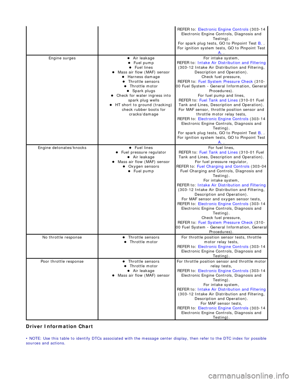
REF E
R to:
Electronic Engine Controls
(303
-14
Electronic Engine Co ntrols, Diagnosis and
Testing).
For spark plug tests, GO to Pinpoint Test B.
.
For ign i
tion system tests, GO to Pinpoint Test
A.
.
Engine s
urges
Air leakage
Fue
l
pump
Fue
l
lines
Mass ai
r fl
ow (MAF) sensor
Harness damage Throttl
e
sensors
Throttl
e
motor
Spark plugs
Check fo
r water ingress into
spark plug wells
HT short to ground (tracking) check rubber
boots for
cracks/damage
Fo r
intake system,
REFER to: Intake Air Distribution and Filtering
(30 3
-12 Intake Air Distribution and Filtering,
Description and Operation). Check fuel pressure,
REFER to: Fuel System Pressure Check
(310
-
00 Fuel System - Genera l Information, General
Procedures).
For fuel pump and lines,
REFER to: Fuel Tank and Lines
(310
-01 Fuel
Tank and Lines, Description and Operation).
For MAF sensor, throttle position sensor and
throttle motor relay tests,
REFER to: Electronic Engine Controls
(303
-14
Electronic Engine Co ntrols, Diagnosis and
Testing).
For spark plug tests, GO to Pinpoint Test B.
.
For ign i
tion system tests, GO to Pinpoint Test
A.
.
Engine detonates/k
nocks
Fue
l
lines
F
u
el pressure regulator
Air leakage
Mass air fl
ow (MAF) sensor
O
xygen senso
rs
Fue
l
pump
F
o
r fuel lines,
REFER to: Fuel Tank and Lines
(310
-01 Fuel
Tank and Lines, Description and Operation).
For fuel pressure regulator,
REFER to: Fuel Charging and Controls
(303
-04
Fuel Charging and Controls, Diagnosis and Testing).
For intake system,
REFER to: Intake Air Distribution and Filtering
(30 3
-12 Intake Air Distribution and Filtering,
Description and Operation).
For MAF sensor and oxyg en sensor tests,
REFER to: Electronic Engine Controls
(303
-14
Electronic Engine Co ntrols, Diagnosis and
Testing).
Check fuel pressure,
REFER to: Fuel System Pressure Check
(310
-
00 Fuel System - Genera l Information, General
Procedures).
No t
hrottle response
Throttl
e
sensors
Throttl
e
motor
Fo
r th
rottle position sensor tests, throttle
motor relay tests,
REFER to: Electronic Engine Controls
(303
-14
Electronic Engine Co ntrols, Diagnosis and
Testing).
Poor throttle responseThrottl e
sensors
Throttl
e
motor
Air leakage Mass air fl
ow (MAF) sensor
F
or throttl
e position se
nsor and throttle motor
relay tests,
REFER to: Electronic Engine Controls
(303
-14
Electronic Engine Co ntrols, Diagnosis and
Testing).
For intake system,
REFER to: Intake Air Distribution and Filtering
(30 3
-12 Intake Air Distribution and Filtering,
Description and Operation). For MAF sensor tests,
REFER to: Electronic Engine Controls
(303
-14
Electronic Engine Co ntrols, Diagnosis and
Testing).
Page 1082 of 2490
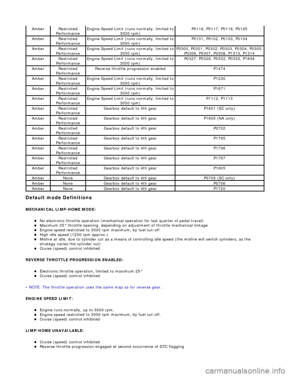
Default mode Definitions
MECHANIC
AL LIMP-HOME MODE:
No elec
tronic throttle operation (mechanical
operation for last quarter of pedal travel)
Ma
ximum 25° throttle opening,
depending on adjustment of th rottle mechanical linkage
Engine speed restri
cted to 3000
rpm maximum, by fuel cut-off
High i
dle speed (1200 rpm approx.)
Misfire
at idle, due
to cylinder cut as a means of control
ling idle speed (the misfire will switch cylinders, as the
strategy varies th e cylinder cut)
Cruise (speed) contr o
l inhibited
REVERSE THROTTLE PROGRESSION ENABLED:
Elec
tronic throttle operation, limited to maximum 25°
Cruise (speed) contr
o
l inhibited
• NOTE: The throttle oper ation uses the same map as for reverse gear.
ENGINE SPEED LIMIT:
Engine runs
normally, up to 3000 rpm.
Engine
speed restri
cted to 3000 rp
m maximum, by fuel cut-off.
Cruise (speed) contr o
l inhibited
LIMP-HOME UNAVAILABLE:
Cruise (speed) contro
l inhibited
Re
verse throttle pr
ogression engaged at second occurrence of DTC flagging
AmberRestri
cted
Performance
Engine
Speed Limit (runs normally, limited to
3000 rpm)
P01 16,
P0117, P0118, P0125
Ambe
rRestri
cted
Performance
Engine
Speed Limit (runs normally, limited to
3000 rpm)
P01 01,
P0102, P0103, P0104
Ambe
rRestri
cted
Performance
Engine
Speed Limit (runs normally, limited to
3000 rpm)
P03 00,
P0301, P0302, P0303, P0304, P0305,
P0306, P0307, P0308, P1313, P1314
Ambe rRestri
cted
Performance
Engine
Speed Limit (runs normally, limited to
3000 rpm)
P03 27,
P0328, P0332, P0333, P1648
Ambe
rRestri
cted
Performance
R e
verse throttle pr
ogression enabled
P1474
AmberRestri
cted
Performance
Engine
Speed Limit (runs normally, limited to
3000 rpm)
P1230
Ambe rRestri
cted
Performance
Engine
Speed Limit (runs normally, limited to
3000 rpm)
P1671
Ambe rRestri
cted
Performance
Engine
Speed Limit (runs normally, limited to
3000 rpm)
P11 12,
P1113
Ambe
rRestri
cted
Performance
Gearbox defau l
t to 4th gear
P1601 (SC on
ly)
AmberRestri
cted
Performance
Gearbox defau l
t to 4th gear
P16
05 (
NA only)
Ambe
rRestri
cted
Performance
Gearbox defau l
t to 4th gear
P0702
Ambe
rRestri
cted
Performance
Gearbox defau l
t to 4th gear
P1795
Ambe
rRestri
cted
Performance
Gearbox defau l
t to 4th gear
P1796
Ambe
rRestri
cted
Performance
Gearbox defau l
t to 4th gear
P1797
Ambe
rRestri
cted
Performance
Gearbox defau l
t to 4th gear
P1605
Ambe
rNoneGearbox defau l
t to 4th gear
P0705 (SC on
ly)
AmberNoneGearbox defau l
t to 4th gear
P0706
Ambe
rNoneGearbox defau l
t to 4th gear
P1720
Page 1083 of 2490
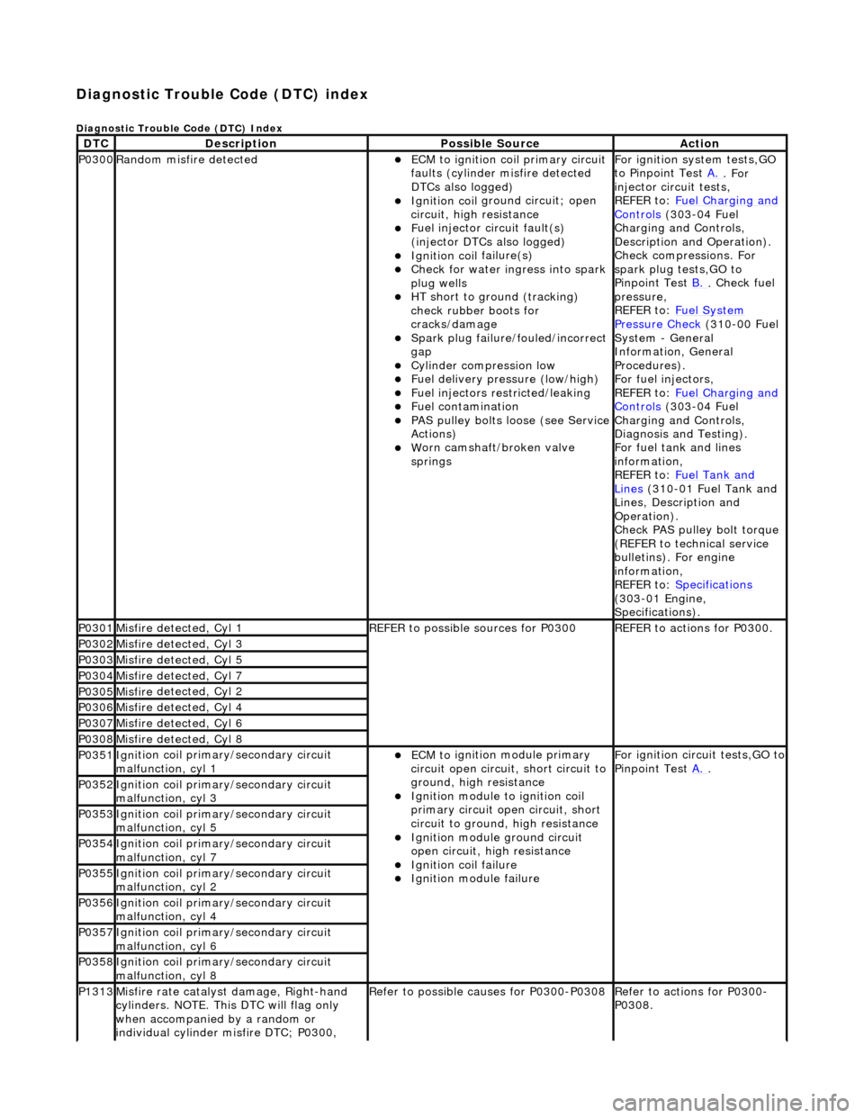
Diagnostic Trouble Code (D
TC) index
D
iagnostic Trouble Code (DTC) Index
DT
C
De
scription
Possib
le Source
Acti
on
P0300Ran
dom misfire detected
ECM t
o ignition coil primary circuit
faults (cylinder misfire detected
DTCs also logged)
Ignition coil
ground circuit; open
circuit, high resistance
F
uel injector circuit fault(s)
(injector DTCs also logged)
Ignition coil
failure(s)
Check f
or water ingress into spark
plug wells
HT sho
rt to ground (tracking)
check rubber boots for
cracks/damage
Spark plug
failure/fouled/incorrect
gap
Cy
linder compression low
F
uel delivery pressure (low/high)
F
uel injectors restricted/leaking
Fuel contamination
P
AS pulley bolts loose (see Service
Actions)
W
orn camshaft/broken valve
springs
For ign
ition system tests,GO
to Pinpoint Test A.
. For
inje
ctor circuit tests,
REFER to: Fuel Charging and
Controls (30
3-04 Fuel
Charging and Controls,
Description and Operation).
Check compressions. For
spark plug tests,GO to
Pinpoint Test B.
.
Check fuel
pressure,
REFER to: Fuel System
Pressure Check (31
0-00 Fuel
System - General
Information, General
Procedures).
For fuel injectors,
REFER to: Fuel Charging and
Controls (30
3-04 Fuel
Charging and Controls,
Diagnosis and Testing).
For fuel tank and lines
information,
REFER to: Fuel Tank and
Lin
es
(310-01 Fuel Tank and
Lines, Description and
Operation).
Check PAS pulley bolt torque
(REFER to technical service
bulletins). For engine
information,
REFER to: Specifications
(3
03-01 Engine,
Specifications).
P0301Misfire
detected, Cyl 1
R
EFER to possible sources for P0300
R
EFER to actions for P0300.
P0302Misfire
detected, Cyl 3
P0303Misfire
detected, Cyl 5
P0304Misfire
detected, Cyl 7
P0305Misfire
detected, Cyl 2
P0306Misfire
detected, Cyl 4
P0307Misfire
detected, Cyl 6
P0308Misfire
detected, Cyl 8
P0351Igni
tion coil primary/secondary circuit
malfunction, cyl 1
ECM to
ignition module primary
circuit open circuit, short circuit to
ground, high resistance
Igni
tion module to ignition coil
primary circuit open circuit, short
circuit to ground, high resistance
Ignition modu
le ground circuit
open circuit, hi gh resistance
Ignition coil
failure
Ignition modul
e failure
F
or ignition circuit tests,GO to
Pinpoint Test A.
.
P0352Igni
tion coil primary/secondary circuit
malfunction, cyl 3
P0353Igni
tion coil primary/secondary circuit
malfunction, cyl 5
P0354Igni
tion coil primary/secondary circuit
malfunction, cyl 7
P0355Igni
tion coil primary/secondary circuit
malfunction, cyl 2
P0356Igni
tion coil primary/secondary circuit
malfunction, cyl 4
P0357Igni
tion coil primary/secondary circuit
malfunction, cyl 6
P0358Igni
tion coil primary/secondary circuit
malfunction, cyl 8
P1313Misfire rate
catalyst damage, Right-hand
cylinders. NOTE. This DTC will flag only
when accompanied by a random or
individual cylinder misfire DTC; P0300,
R
efer to possible causes for P0300-P0308
R
efer to actions for P0300-
P0308.
Page 1084 of 2490
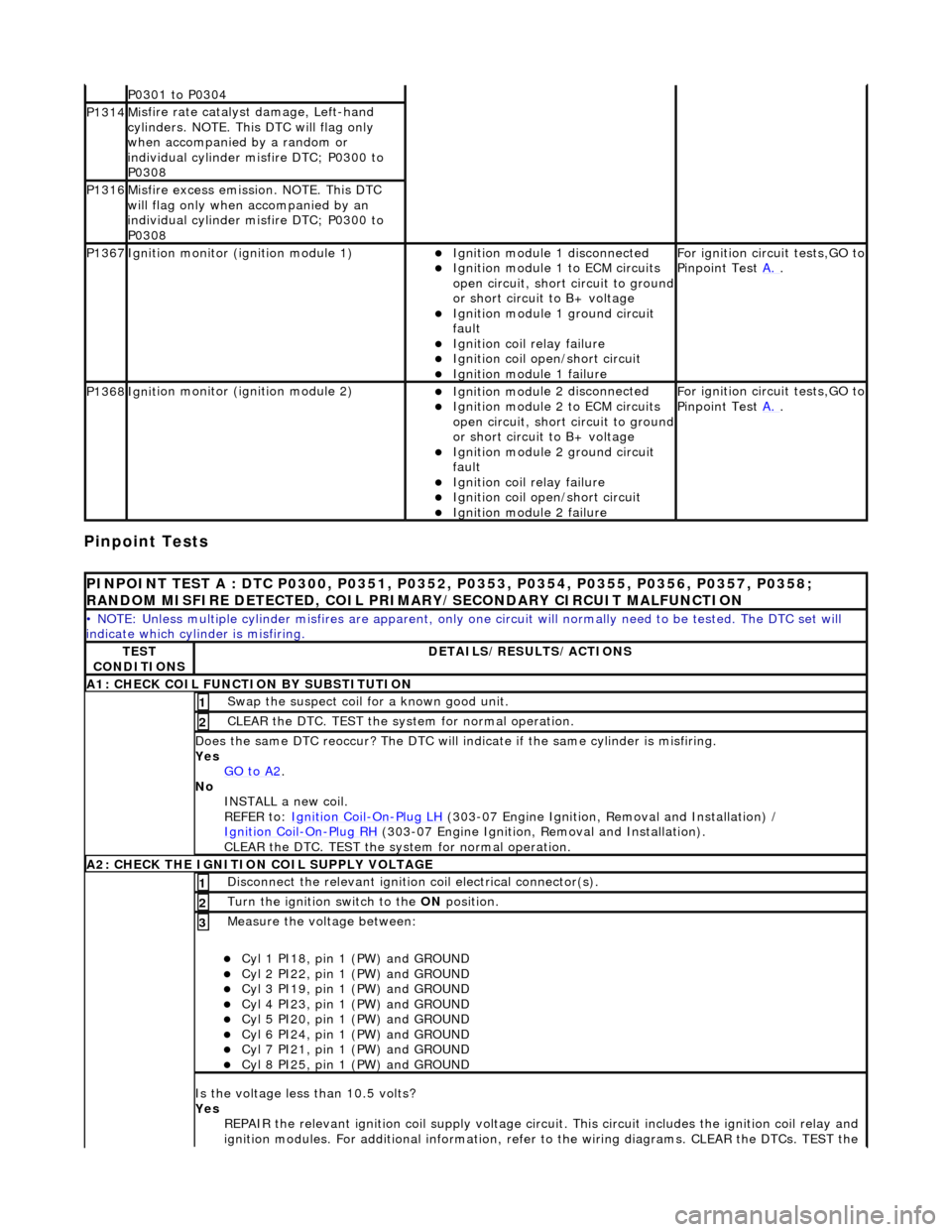
Pinpoint Tests
P0301 t
o P0304
P1314M
i
sfire rate catalyst damage, Left-hand
cylinders. NOTE. This DTC will flag only
when accompanied by a random or
individual cylinder misfire DTC; P0300 to
P0308
P1316M i
sfire excess emission. NOTE. This DTC
will flag only when accompanied by an
individual cylinder misfire DTC; P0300 to
P0308
P1367Ignit i
on monitor (ignition module 1)
Ignition modu
le
1 disconnected
Ignition modul e
1 to ECM circuits
open circuit, short circuit to ground
or short circuit to B+ voltage
Ignition modul e
1 ground circuit
fault
Ignition coil relay fai
lure
Ignition coil open/short
circuit
Ignition module
1 failure
F
o
r ignition circuit tests,GO to
Pinpoint Test A.
.
P1368Igniti
on monitor (ignition module 2)
Ignition modu
le
2 disconnected
Ignition modul e
2 to ECM circuits
open circuit, short circuit to ground
or short circuit to B+ voltage
Ignition modul e
2 ground circuit
fault
Ignition coil relay fai
lure
Ignition coil
open/short
circuit
Ignition modul
e
2 failure
F
o
r ignition circuit tests,GO to
Pinpoint Test A.
.
PINPOINT TES
T A : DTC P0300, P0351, P0352, P0353, P0354, P0355, P0356, P0357, P0358;
RANDOM MISFIRE DETECTED, COIL PRIMARY/SECONDARY CIRCUIT MALFUNCTION
• NO
TE: Unless multiple cylinder misfires are apparent, only on
e circuit will normally need to be tested. The DTC set will
indicate which cylinder is misfiring.
TE S
T
CONDITIONS
D E
TAILS/RESULTS/ACTIONS
A1
: CH
ECK COIL FUNCTI
ON BY SUBSTITUTION
Swap the suspect coi l
for a known good unit.
1
CLEAR t
h
e DTC. TEST the syst
em for normal operation.
2
Do
es the same DTC reoccur? The DTC will indicate if the same cylinder is misfiring.
Yes GO to A2
.
No
INST
ALL a new coil.
REFER to: Ignition Coil
-On-Plug
LH
(30
3-07 Engine Ignition, Removal and Installation) /
Ignition Coil
-On-Plu g
RH
(30
3-07 Engine Ignition, Removal and Installation).
CLEAR the DTC. TEST the system for normal operation.
A2: CHECK THE IGNIT
ION COIL SUPPLY VOLTAGE
Disc
onne
ct the relevant ignition
coil electrical connector(s).
1
Turn the ignition swit
ch to the ON
position.
2
Measure the voltage between:
Cyl 1 PI18, pin
1 (PW) and GROUND
Cy
l 2 PI22, pin
1 (PW) and GROUND
Cy
l 3 PI19, pin
1 (PW) and GROUND
Cy
l 4 PI23, pin
1 (PW) and GROUND
Cy
l 5 PI20, pin
1 (PW) and GROUND
Cy
l 6 PI24, pin
1 (PW) and GROUND
Cy
l 7 PI21, pin
1 (PW) and GROUND
Cy
l 8 PI25, pin
1 (PW) and GROUND
3
Is
t
he voltage less than 10.5 volts?
Yes REPAIR the relevant ignition coil su pply voltage circuit. This circuit includes the ignition coil relay and
ignition modules. For additional information, refer to the wiring diagrams. CLEAR the DTCs. TEST the
Page 1086 of 2490
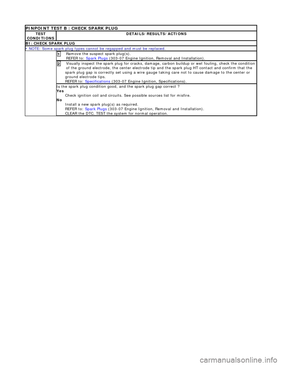
PINPOINT TEST B : CHECK SPARK PLUG
TE S
T
CONDITIONS
D E
TAILS/RESULTS/ACTIONS
B1
: CH
ECK SPARK PLUG
•
NOTE
: Some spark plug types cannot
be regapped and must be replaced.
Re
move the suspect spark plug(s).
REFER to: Spark Plugs
(30
3-07 Engine Ignition,
Removal and Installation).
1
Visuall
y inspect the spark plug for cracks, damage,
carbon buildup or wet fouling, check the condition
of the ground electrode, the center electrode tip and the spark plug HT contact and confirm that the
spark plug gap is correctly set usin g a wire gauge taking care not to cause damage to the center or
ground electrode tips.
REFER to: Specifications
(30
3-07 Engine Ignition, Specifications).
2
Is th
e s
park plug condition good,
and the spark plug gap correct ?
Yes Check ignition coil and circuits. See possible sources list for misfire.
No Install a new spark pl ug(s) as required.
REFER to: Spark Plugs
(30
3-07 Engine Ignition, Removal and Installation).
CLEAR the DTC. TEST the syst em for normal operation.
Page 1094 of 2490
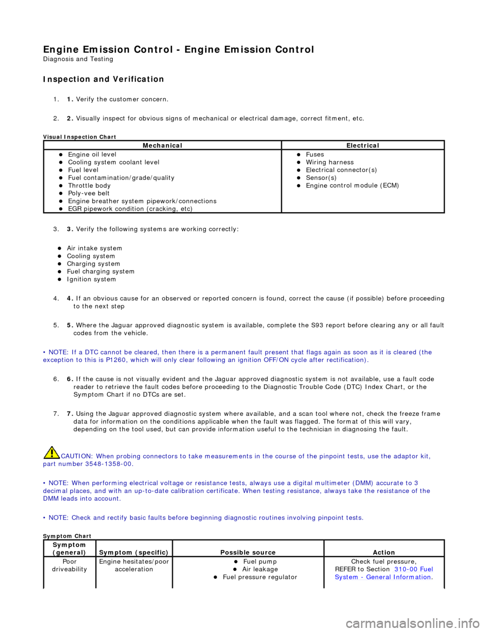
Engine Emission
Control - Engine Emission Control
D
iagn
osis and Testing
I
n
spection and Verification
1.
1. Veri fy the customer concern.
2. 2. Vis
ually inspect for obvious signs of mechanical
or electrical damage, correct fitment, etc.
Vi
sual Inspection Chart
3.
3. Veri fy the foll
owing syst
ems are working correctly:
Air intake
system
Coo
ling system
Charging system
Fu
el charging system
Ignition sys
t
em
4. 4. If an obvious cause for an observed or reported concern is found, correct the cause (if possible) before proceeding
to the next step
5. 5. Where the Jaguar approved diagnostic sy stem is available, complete the S93 report before clearing any or all fault
codes from the vehicle.
• NOTE: If a DTC cannot be cleared, then there is a permanent fault present that flag s again as soon as it is cleared (the
exception to this is P1260, which will only clear following an ignition OFF/ON cycle after rectification).
6. 6. If the cause is not visually evident and the Jaguar approv ed diagnostic system is not available, use a fault code
reader to retrieve the fault codes be fore proceeding to the Diagnostic Trou ble Code (DTC) Index Chart, or the
Symptom Chart if no DTCs are set.
7. 7. Using the Jaguar approved diagnostic system where available, and a scan tool where not, check the freeze frame
data for information on the conditions applicable when the fault was flagged. The format of this will vary,
depending on the tool used, but can pr ovide information useful to the technician in diagnosing the fault.
CAUTION: When probing connectors to take measurements in the course of the pinpoint tests, use the adaptor kit,
part number 3548-1358-00.
• NOTE: When performing electrical voltag e or resistance tests, always use a digital multimeter (DMM) accurate to 3
decimal places, and with an up-t o-date calibration certificate. When testing resistance, always take the resistance of the
DMM leads into account.
• NOTE: Check and rectify basic faults before beginning diagnostic ro utines involving pinpoint tests.
Sym
ptom Chart
MechanicalElectrical
Engi
ne
oil level
Coo
ling system coolant level
Fue
l
level
Fuel contaminatio
n
/
grade/quality
Throttle body Poly
-ve
e belt
Engine breath
er
system
pipework/connections
EGR pipework
condition (cracking, etc)
F
u
ses
W
i
ring harness
E
l
ectrical connector(s)
Sens
o
r(s)
Engine
control module (E
CM)
Sy
m
ptom
(general)
S y
mptom (specific)
Possib
l
e source
Acti
o
n
Poor
dr iveabilityEngine h e
sitates/poor
acceleration
Fue l
pump
Air leakage F
u
el pressure regulator
Chec
k fu
el pressure,
REFER to Section 310
-00 Fu
el
Sy
ste
m
- General Informati
on.