Page 542 of 2490
Re
move fuse F12
1
W
i
th EM015, EM014, PI031 and PI032 disconnected,
measure the voltage between EM015/008 and
EM014/009
2
0 V?
Yes
Reconnect EM015 and EM0 14 and replace fuse F12
GO to C4
No Inspect EM015, PI001 or PI032 for bent / pushed back
pins or locate and repair the harness / connector. Test the
system for normal operation.
C4 :
CHECK B+ AT VVT SOLENOID
Page 644 of 2490
15. Di
sconnect the air cleaner cover.
R
e
lease the five clips which se
cure the air cleaner cover.
16. Disconnect the air flow meter multi-plug.
17 . R
emove the intake tube / air
flow meter / air cleaner cover
assembly.
1. Remove the intake tube / air flow meter / air cleaner
cover assembly.
2. Remove and discard the ru bber seal; air intake tube
to throttle body.
18. Remove the purge valve, fro m the evaporative control
system. Refer to Operation 17.45.01.
19. Remove the on-plug ignition coils. Refer to Operation
18.20.41 and 18.20.42.
20. Remove the camshaft covers. Refer to Operations 12.29.43
and 12.29.44.
21. Remove the variable valve ti ming solenoids. Refer to
Operation18.30.63.
22. Disconnect the engine harness retaining clips from the timing
cover.
Page 648 of 2490
8. Re
fit the variable valve timing
solenoids. Refer to Operation
18.30.63.
9. Refit the camshaft covers. Refer to Operations 12.29.43.and
12.29.44.
10. Refit the on-plug ignition coils and coil covers. Refer to
Operation 18.20.41 and 18.20.42.
11. Refit the purge valve. Refer to Operation 17.45.01.
12 . F
it the intake tube / air flow meter / air cleaner cover
assembly.
1. Fit a new rubber seal; air in take tube to throttle body.
2.
Fit the intake tube / air
flow meter / air cleaner cover
assembly.
13 . R
econnect the air cleaner cover.
F
it
the five clips which secu
re the air cleaner cover.
14. Co
nnect the intake tube to the throttle body.
1. Connect the intake tube to the throttle body.
2. Fit the two bolts which secure the intake tube to the throttle body.
Page 653 of 2490
15
.
Disconnect the air cleaner cover.
R
elease the five clips which se
cure the air cleaner cover.
16. Disconnect the air flow meter multi-plug.
17
.
Remove the intake tube / air flow meter / air cleaner cover
assembly.
1. Remove the intake tube / air flow meter / air cleaner
cover assembly.
2. Remove and discard the ru bber seal; air intake tube
to throttle body.
18. Remove the purge valve, fro m the evaporative control
system. Refer to Operation 17.45.01.
19. Remove the on-plug ignition coils. Refer to Operation
18.20.41 and 18.20.42.
20. Remove the camshaft covers. Refer to Operations 12.29.43
and 12.29.44.
21. Remove the variable valve ti ming solenoids. Refer to
Operation18.30.63.
22. Disconnect the engine harness retaining clips from the timing
cover.
Page 657 of 2490
7. Reposition and secure the engine harness clips to the timing
cover.
8. Refit the variable valve timing solenoids. Refer to Operation
18.30.63.
9. Refit the camshaft covers. Refer to Operations 12.29.43.and
12.29.44.
10. Refit the on-plug ignition coils and coil covers. Refer to
Operation 18.20.41 and 18.20.42.
11. Refit the purge valve. Refer to Operation 17.45.01.
12. Fit the intake tube / air flow meter / air cleaner cover
assembly.
1. Fit a new rubber seal; air in take tube to throttle body.
2. Fit the intake tube / air flow meter / air cleaner cover
assembly.
Page 1015 of 2490

Fuel D
istribution
Fuel is supplied to th
e engine
via eight fuel injectors (one pe r cylinder). The injectors are located in two fuel rails which r un
the length of each cylinder bank and ar e integral with the air intake manifold.
Fuel pumped from the tank enters a feed pipe at the rear of bank 2. Fuel flow is along bank 2 fuel rail, across the top front
of the engine (cross-over pipe) and through bank 1 fuel rail, the unused fuel re turning to the tank via a pressure regulator.
The fuel injectors are each controlled electrically from the engine control module (ECM).
A test valve is fitted to the cross-over pipe connecting the fu el rails at the front of the intake manifold. This valve allows the
fuel system to be depr essurized during servicin g and troubleshooting.
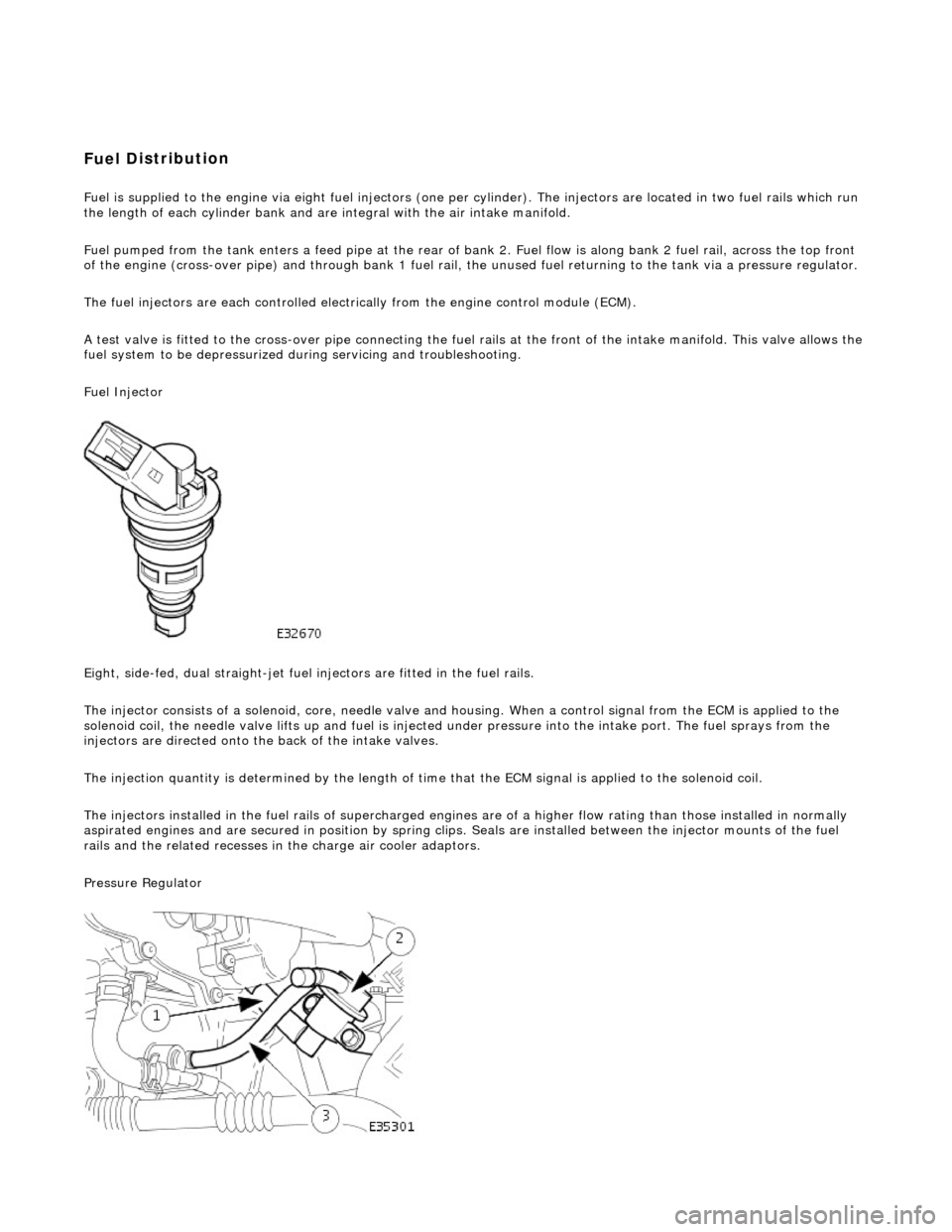
Fuel Injector
Eight, side-fed, dual straight-jet fuel injectors are fi tted in the fuel rails.
The injector consists of a solenoid, core, needle valve and ho using. When a control signal from the ECM is applied to the
solenoid coil, the needle valve lifts up and fuel is injected under pressure into the intake port. The fuel sprays from the
injectors are directed onto the back of the intake valves.
The injection quantity is determined by the length of time that the ECM signal is applied to the solenoid coil.
The injectors installed in the fuel rails of supercharged engines are of a higher flow rating than those installed in normally
aspirated engines and are secured in position by spring clips. Seals are instal led between the injector mounts of the fuel
rails and the related re cesses in the charge air cooler adaptors.
Pressure Regulator
Page 1062 of 2490
Starting System - Starting System
Description and Operation
Manufacturer - NipponDenso
Type - RA1.4.
Weight - 3.75 kg (8.27 lb)
Output - 1.4 kW
Rated Time - 30 seconds
Rotation - Clockwise, viewed from pinion end
The starter is of the pre-engaged type; loca ted at the rear left-side of the engine.
When the starter is operated from the key-switch, the engagement lever moves the pinion into mesh with the engine ring
gear teeth, the electrical contacts within the solenoid complete the high power circuit and the starter motor operates to turn
the engine.
Starter Relay
The starter motor control relay is, relay nu mber 5, located inside the engine compartment enclosure (left side of vehicle
RHD and right side of vehicle on LHD).
Page 1064 of 2490

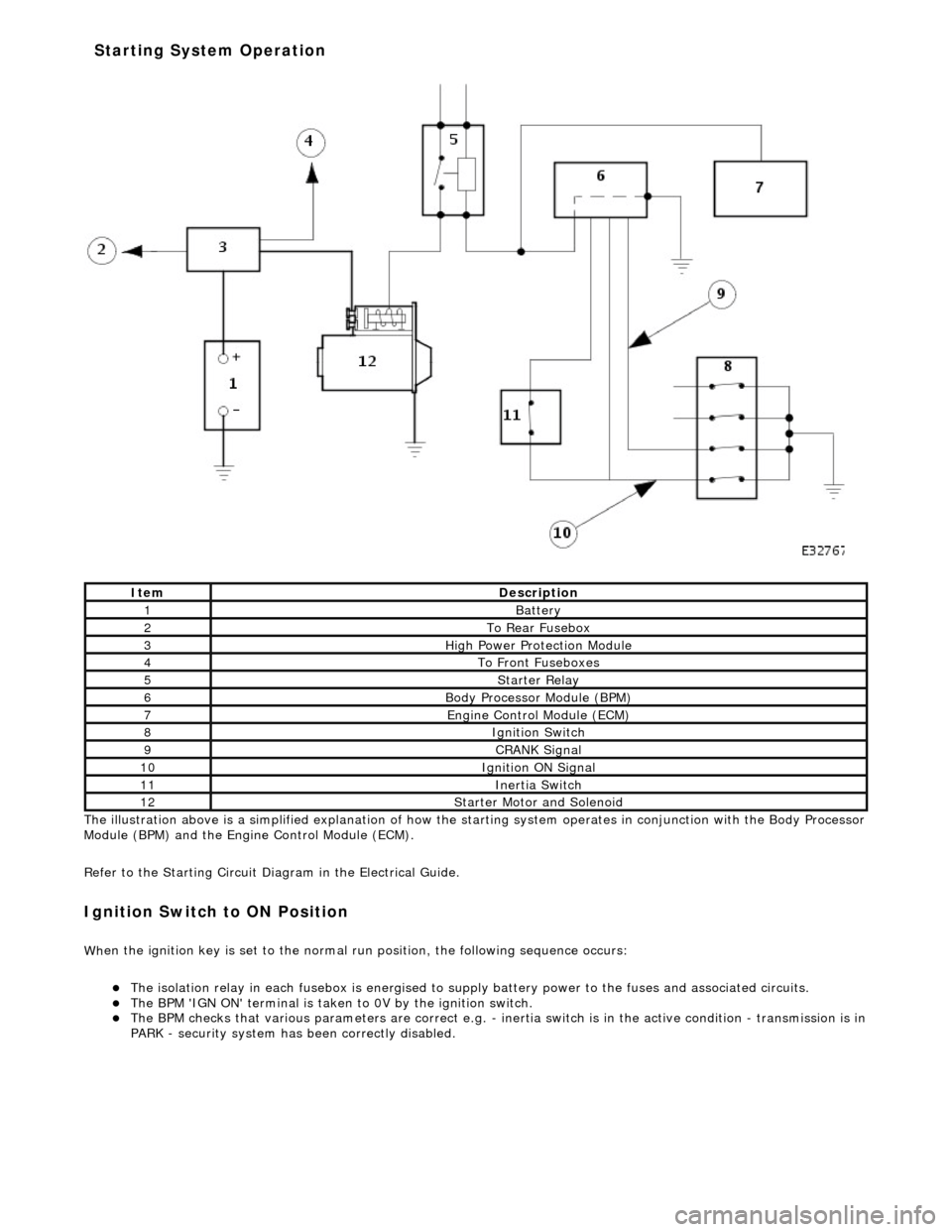
The il
lustration above is a simplified expl
anation of how the starting system operates in conjunction with the Body Processor
Module (BPM) and the Engine Control Module (ECM).
Refer to the Starting Circuit Diagram in the Electrical Guide.
I g
nition Switch to ON Position
W
h
en the ignition key is set to the normal run position, the following sequence occurs:
The
is
olation relay in each fusebox is
energised to supply battery power to the fuses and associated circuits.
The BPM 'IGN
ON' terminal
is taken to 0V by the ignition switch.
The BPM
checks that various parameters are correct e.g. -
inertia switch is in the active condition - transmission is in
PARK - security system has been correctly disabled.
It e
m
De
scr
iption
1Batt
ery
2To Re ar
Fusebox
3Hi
gh Power Pr
otection Module
4To Front
Fu
seboxes
5Starter Re
lay
6Body Processor M
odule (BPM)
7Engine
C
ontrol Module (ECM)
8Ignition Switch
9CRANK Signal
10Ignition ON Signal
11Inertia Switch
12St
arte
r Motor and Solenoid
Starting System Operation