1998 JAGUAR X308 Engine system - general
[x] Cancel search: Engine system - generalPage 991 of 2490

Engine Cooling - Radiator Upper Hose4.0L SC V8 - AJ26
Re
moval and Installation
Remov
al
Installation
1.
O
pen the engine compartment and fit paintwork protection
sheets.
2. Drain the radiator. Refer to Ge neral Procedures. Retain the
coolant drain tray in position to catch any spillage when
removing the hose.
3. Di
sconnect the top hose from the coolant outlet pipe.
1. Release and reposition th e hose clip, and disconnect
the top hose.
4. R
elease the top hose from the radiator.
1. Release the hose retaining clip and reposition the clip along the hose.
2. Disconnect the hose from the radiator.
Re
move the hose clips from the top hose.
1. Installation is th e reverse of the re moval procedure.
2. Refill the cooling system as de scribed in General Procedures.
Page 994 of 2490

Engine Cooling - Thermostat4.0L SC V8 - AJ26
Remo
val and Installation
Remov
a
l
Installation
1.
Op
en the engine compartment and fit paintwork protection
sheets.
2. Drain the radiator. Refer to Ge neral Procedures. Retain the
coolant drain tray in position to catch any spillage when
removing the outlet pipe.
3. Disc
onnect the bottom hose
from the coolant outlet pipe.
1. Release and reposi tion the hose clip.
2. Disconnect the bottom hose.
4. Re
move the thermostat from the outlet pipe.
1. Remove the three bolts which secure the thermostat cover to the outlet pipe.
2. Remove the thermostat cover, the thermostat and
the seal from the outlet pipe. Discard the seal.
1. Installation is th e reverse of the re moval procedure.
Use new seali
ng rings on th
e coolant outlet pipe and
thermostat housing.
The t he
rmostat ball valve must
locate in the recess in the
cover.
2. Tighten the thermostat cover bolts to 8-10 Nm.
3. Refill the cooling system as de scribed in General Procedures.
Page 997 of 2490

Engine Cooling - Thermostat Housing Cover4.
0L SC V8 - AJ26
Re
moval and Installation
Remov
al
Installation
1.
O
pen the engine compartment and fit paintwork protection
sheets.
2. Drain the radiator. Refer to Ge neral Procedures. Retain the
coolant drain tray in position to catch any spillage when
removing the outlet pipe.
3. Di
sconnect the bottom hose
from the coolant outlet pipe.
1. Release and reposi tion the hose clip.
2. Disconnect the bottom hose.
4. R
emove the thermostat from the outlet pipe.
1. Remove the three bolts which secure the thermostat cover to the outlet pipe.
2. Remove the thermostat cover, the thermostat and
the seal from the outlet pipe. Discard the seal.
1. Installation is th e reverse of the re moval procedure.
Use new
sealing rings on th
e coolant outlet pipe and
thermostat housing.
The t
hermostat ball valve must
locate in the recess in the
cover.
2. Tighten the thermostat cover bolts to 8-10 Nm.
3. Refill the cooling system as de scribed in General Procedures.
Page 1000 of 2490

Engine Cooli
ng - Thermostat Housin
g Cover Seal4.0L SC V8 - AJ26
Remo
val and Installation
Remov
a
l
Installation
1.
Op
en the engine compartment and fit paintwork protection
sheets.
2. Drain the radiator. Refer to Ge neral Procedures. Retain the
coolant drain tray in position to catch any spillage when
removing the outlet pipe.
3. Disc
onnect the bottom hose
from the coolant outlet pipe.
1. Release and reposi tion the hose clip.
2. Disconnect the bottom hose.
4. Re
move the thermostat from the outlet pipe.
1. Remove the three bolts which secure the thermostat cover to the outlet pipe.
2. Remove the thermostat cover, the thermostat and
the seal from the outlet pipe. Discard the seal.
1. Installation is th e reverse of the re moval procedure.
Use new seali
ng rings on th
e coolant outlet pipe and
thermostat housing.
The t he
rmostat ball valve must
locate in the recess in the
cover.
2. Tighten the thermostat cover bolts to 8-10 Nm.
3. Refill the cooling system as de scribed in General Procedures.
Page 1026 of 2490

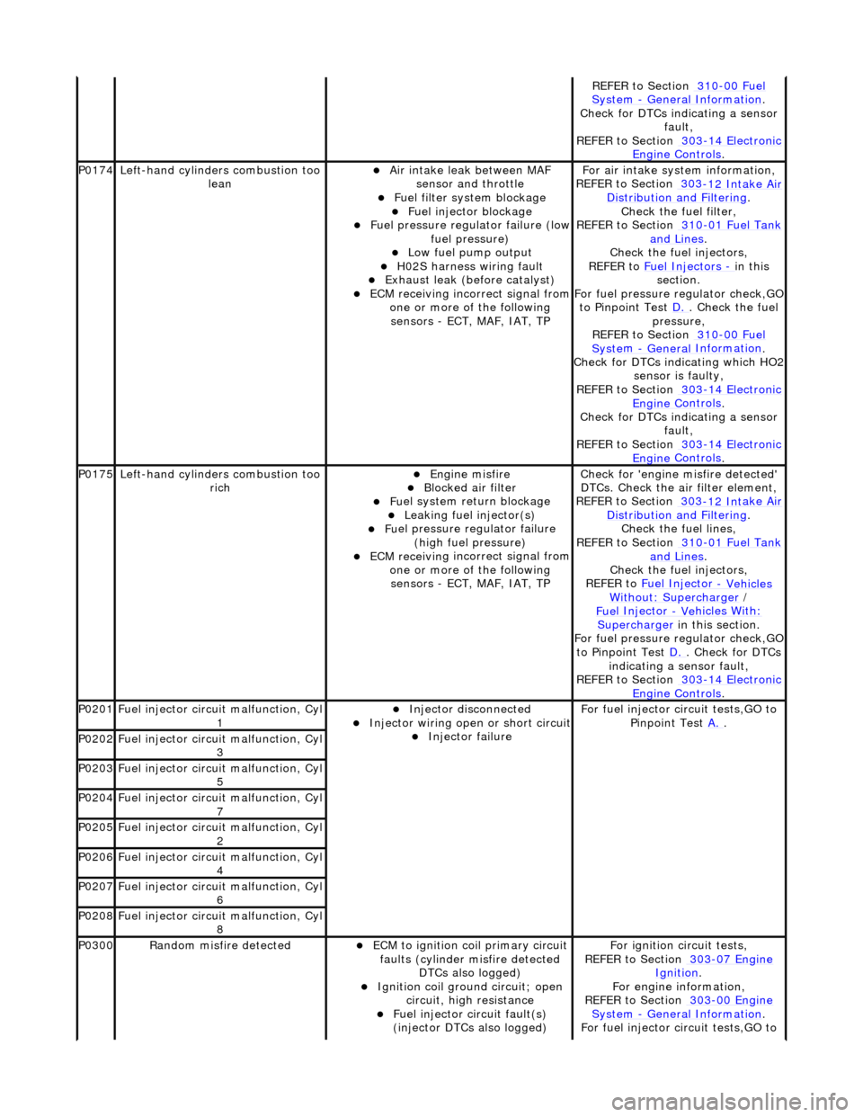
REFE
R to Section 310
-00
Fu
el
Sy
ste
m
- General
Information
.
Check f o
r DTCs indicating a sensor
fault,
REFER to Section 303
-14 El
ectronic
Engine
C
ontrols
.
P0174
Left-hand cyl i
nders combustion too
lean
Air in
take leak between MAF
sensor and throttle
F u
el filter system blockage
F
u
el injector blockage
F
u
el pressure regulator failure (low
fuel pressure)
Low f u
el pump output
H0
2S harness wiri
ng fault
E
x
haust leak (before catalyst)
ECM receivi
n
g incorrect signal from
one or more of the following sensors - ECT, MAF, IAT, TP
F o
r air intake sy
stem information,
REFER to Section 303
-12 Int
ake Air
Distribu tion and Filterin
g
.
Check the fuel fi lter,
REF
ER to Section 310
-01
Fu
el Tank
and Lines.
Chec k the
fuel injectors,
REFER to Fuel Injectors
- in t h
is
section.
For fuel pressure regulator check,GO
to Pinpoint Test D.
. Ch
eck the fuel
pressure,
REFER to Section 310
-00 Fu
el
Sy
ste
m
- General
Information
.
Check f o
r DTCs indicating which HO2
sensor is faulty,
REFER to Section 303
-14 El
ectronic
Engine
C
ontrols
.
Check f o
r DTCs indicating a sensor
fault,
REFER to Section 303
-14 El
ectronic
Engine
C
ontrols
.
P0175Left-hand cyli
nders combustion too
rich
Engine m
isfire
Bl
ocked air
filter
F
u
el system return blockage
Leak
i
ng fuel injector(s)
F
u
el pressure regulator failure
(high fuel pressure)
ECM receivi n
g incorrect signal from
one or more of the following sensors - ECT, MAF, IAT, TP
Check for 'en
gine misfire detected'
DTCs. Check the air filter element,
REFER to Section 303
-12 Int
ake Air
Distribu tion and Filterin
g
.
Chec k the
fuel lines,
REFER to Section 310
-01 Fu
el Tank
and Lines.
Chec k the
fuel injectors,
REFER to Fuel Injector
- Vehicles Wi
thout: Supercharger
/
Fue
l Injector
- Ve
hicles With
:
Supercharger
in this
section.
For fuel pressure regulator check,GO
to Pinpoint Test D.
. Check for DT
Cs
indicating a sensor fault,
REFER to Section 303
-14 El
ectronic
Engine
C
ontrols
.
P0201F
u
el injector circuit malfunction, Cyl
1
Injector discon n
ected
Inject
or wir
ing open or short circuit
Injector fail
ure
F
o
r fuel injector circuit tests,GO to
Pinpoint Test A.
.
P0202Fu
el injector circuit malfunction, Cyl
3
P0203F u
el injector circuit malfunction, Cyl
5
P0204F u
el injector circuit malfunction, Cyl
7
P0205Fu
el injector circuit malfunction, Cyl
2
P0206Fu
el injector circuit malfunction, Cyl
4
P0207F u
el injector circuit malfunction, Cyl
6
P0208F u
el injector circuit malfunction, Cyl
8
P0300Ran d
om misfire detected
ECM t
o
ignition coil primary circuit
faults (cylinder misfire detected DTCs also logged)
Ignition coil ground circuit; open
ci
rcuit, high resistance
F
u
el injector circuit fault(s)
(injector DTCs also logged)
F o
r ignition circuit tests,
REFER to Section 303
-07 En
gine
Ignition.
F or engi
ne information,
REFER to Section 303
-00 En
gine
Sy
ste
m
- General
Information
.
F o
r fuel injector circuit tests,GO to
Page 1027 of 2490

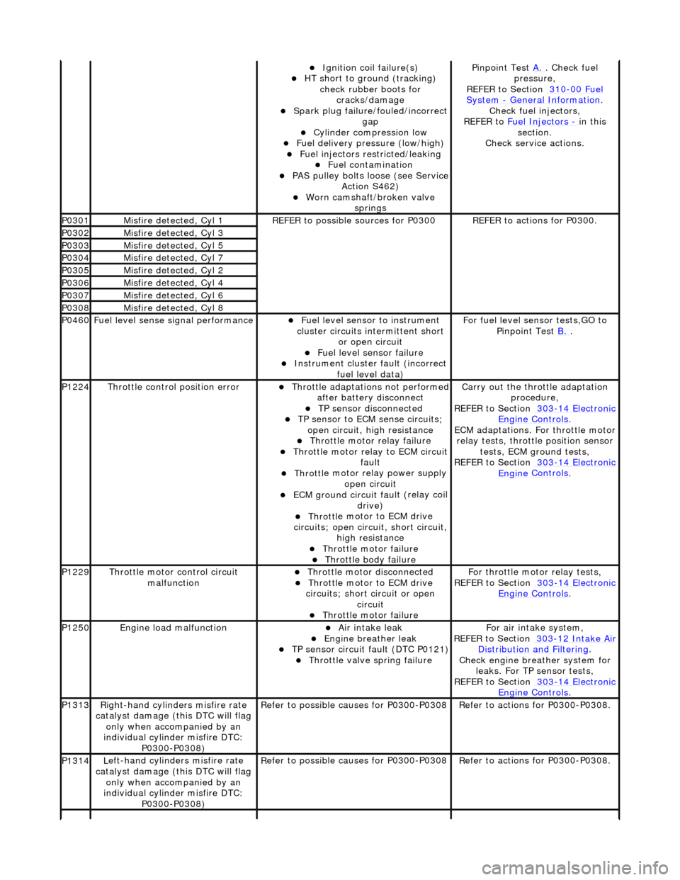
Ignition coil
failure(s)
HT sho
rt to ground (tracking)
check rubber boots for cracks/damage
Spark plug
failure/fouled/incorrect
gap
Cy
linder compression low
F
uel delivery pressure (low/high)
F
uel injectors restricted/leaking
Fuel contamination
P
AS pulley bolts loose (see Service
Action S462)
W
orn camshaft/broken valve
springs
P
inpoint Test
A.
.
Check fuel
pressure,
REFER to Section 310
-00
Fuel
Sy
stem
- General
Information
.
Chec
k fuel injectors,
REFER to Fuel Injectors
- in t
his
section.
Check service actions.
P0301Misfire
detected, Cyl 1
R
EFER to possible sources for P0300
R
EFER to actions for P0300.
P0302Misfire
detected, Cyl 3
P0303Misfire
detected, Cyl 5
P0304Misfire
detected, Cyl 7
P0305Misfire
detected, Cyl 2
P0306Misfire
detected, Cyl 4
P0307Misfire
detected, Cyl 6
P0308Misfire
detected, Cyl 8
P0460F
uel level sense signal performance
Fue
l level sensor
to instrument
cluster circuits in termittent short
or open circuit
F
uel level sensor failure
Instrument cluster
faul
t (incorrect
fuel level data)
F
or fuel level sensor tests,GO to
Pinpoint Test B.
.
P1224Throttl
e control position error
Thro
ttle adaptations not performed
after battery disconnect
TP se
nsor disconnected
TP se
nsor to ECM sense circuits;
open circuit, hi gh resistance
Throttl
e motor relay failure
Th
rottle motor relay to ECM circuit
fault
Throttl
e motor relay power supply
open circuit
ECM ground circuit faul
t (relay coil
drive)
Throttl
e motor to ECM drive
circuits; open circuit, short circuit, high resistance
Throttl
e motor failure
Throttl
e body failure
Carry
out the throttle adaptation
procedure,
REFER to Section 303
-14
Electronic
Engine
Controls
.
ECM adaptations. For
throttle motor
relay tests, throttle position sensor tests, ECM ground tests,
REFER to Section 303
-14
Electronic
Engine
Controls
.
P1229Throttl
e motor control circuit
malfunction
Throttl
e motor disconnected
Throttl
e motor to ECM drive
circuits; short circuit or open circuit
Throttl
e motor failure
Fo
r throttle moto
r relay tests,
REFER to Section 303
-14
Electronic
Engine
Controls
.
P1250Engine
load malfunction
Air
intake leak
Engine
breather leak
TP se
nsor circuit fault (DTC P0121)
Throttl
e valve spring failure
F
or air intake system,
REFER to Section 303
-12
Intake Air
Distribu
tion and Filtering
.
Chec
k engine breather system for
leaks. For TP sensor tests,
REFER to Section 303
-14
Electronic
Engine
Controls
.
P1313Right-hand cylinders misfire rate
cat
alyst damage (this DTC will flag
only when accompanied by an
individual cylinder misfire DTC: P0300-P0308)
R
efer to possible causes for P0300-P0308
R
efer to actions for P0300-P0308.
P1314L
eft-hand cylinders misfire rate
catalyst damage (this DTC will flag only when accompanied by an
individual cylinder misfire DTC: P0300-P0308)
R
efer to possible causes for P0300-P0308
R
efer to actions for P0300-P0308.
Page 1031 of 2490

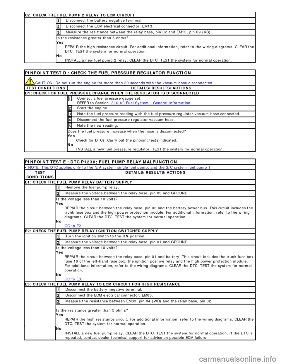
C2: CHECK THE FUEL
PUMP 2 RELAY TO ECM CIRCUIT
Di
sconnect the battery negative terminal.
1
D
isconnect the ECM electrical connector, EM13.
2
Meas
ure the resistance between the rela
y base, pin 02 and EM13, pin 09 (KB).
3
Is th
e resistance greater than 5 ohms?
Yes REPAIR the high resistance circuit. For additional information, refer to the wiring diagrams. CLEAR the
DTC. TEST the system for normal operation.
No INSTALL a new fuel pump 2 relay. CLEAR the DT C. TEST the system for normal operation.
P
INPOINT TEST D : CHECK THE FUEL PRESSURE REGULATOR FUNCTION
CAUTI
ON: Do not run the engine for more than
30 seconds with the vacuum hose disconnected.
T
EST CONDITIONS
D
ETAILS/RESULTS/ACTIONS
D
1: CHECK FOR FUEL PRESSURE CHANGE
WHEN THE REGULATOR IS DISCONNECTED
Connect a
fuel pressure gauge set,
REFER to Section 310
-00
Fuel System
-
General Informati
on
. 1
St
art the engine.
2
N
ote the fuel pressure readin
g with the fuel pressure regu lator vacuum hose connected.
3
Di
sconnect the fuel pressu
re regulator vacuum hose.
4
N
ote the new reading.
5
Doe
s the fuel pressure increase when the hose is disconnected?
Yes Check for DTCs. Carry out the pinpoint tests indicated.
No INSTALL a new fuel presssure regulator. TEST the system for normal operation.
P
INPOINT TEST E : DTC P1230;
FUEL PUMP RELAY MALFUNCTION
•
NOTE: This DTC applies only to the N/A system si
ngle fuel pump, and the S/C system fuel pump 1
TE
ST
CONDITIONS
D
ETAILS/RESULTS/ACTIONS
E1
: CHECK THE FUEL PUMP
RELAY BATTERY SUPPLY
R
emove the fuel pump relay.
1
Meas
ure the voltage between the
relay base, pin 03 and GROUND.
2
Is th
e voltage less than 10 volts?
Yes REPAIR the circuit between the rela y base, pin 03 and the battery power bus. This circuit includes the
trunk fuse box and the high power protection module . For additional information, refer to the wiring
diagrams. CLEAR the DTC. TEST th e system for normal operation.
No GO to E2
.
E2
: CHECK THE FUEL PUMP RELAY IGNITION SWITCHED SUPPLY
Turn the ignition swi
tch to the
ON position.
1
Meas
ure the voltage between the
relay base, pin 01 and GROUND.
2
Is th
e voltage less than 10 volts?
Yes REPAIR the circuit between the rela y base, pin 01 and battery. This circuit includes the trunk fuse box,
fuse 16 of the left-hand fuse box, the ignition po
sitive relay and the high power protection module.
For additional information, refer to the wiring diagrams. CLEAR the DTC. TEST the system for normal
operation.
No GO to E3
.
E3
: CHECK THE FUEL PUMP RELAY TO
ECM CIRCUIT FOR HIGH RESISTANCE
Di
sconnect the battery negative terminal.
1
D
isconnect the ECM electrical connector, EM83.
2
Meas
ure the resistance between EM83, pi
n 04 (WR) and the relay base, pin 02.
3
Is th
e resistance greater than 5 ohms?
Yes REPAIR the high resistance circuit. For additional information, refer to the wiring diagrams. CLEAR the
DTC. TEST the system for normal operation.
No
INSTALL a new fuel pump relay. CLEAR the DTC. TEST the system for normal operation. If the DTC is
repeated, contact dealer technical support for advice on possible ECM failure.
Page 1078 of 2490

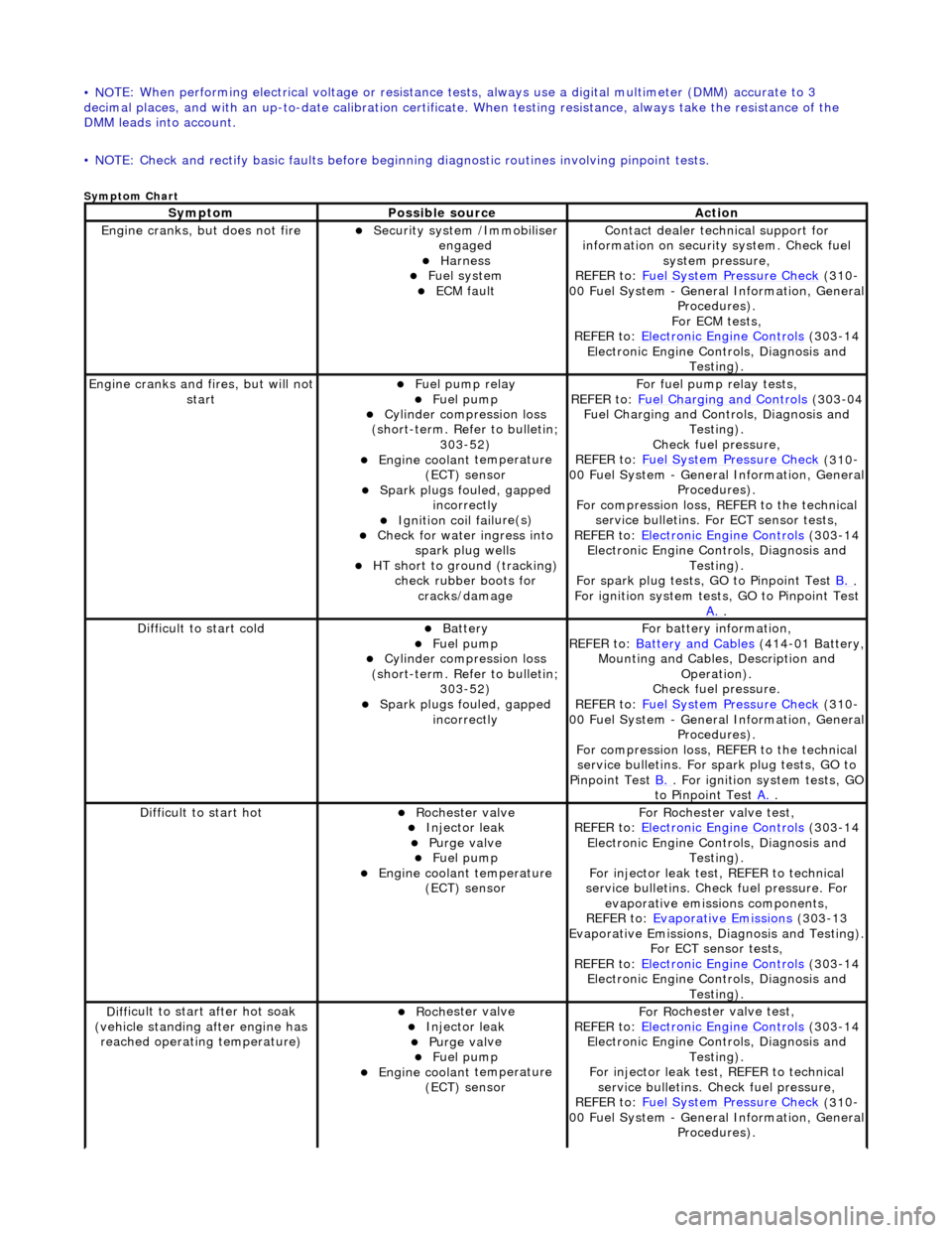
• NO
TE: When performing electrical voltag
e or resistance tests, always use a digital multimeter (DMM) accurate to 3
decimal places, and with an up-t o-date calibration certificate. When testing resistance, always take the resistance of the
DMM leads into account.
• NOTE: Check and rectify basic faults before beginning diagnostic ro utines involving pinpoint tests.
Sym
ptom Chart
Sy
m
ptom
Possib
l
e source
Acti
o
n
Engine
cranks, but does
not fire
Secu
rit
y system /Immobiliser
engaged
Harness Fue l
system
ECM fault
Contact deal er techni
cal support for
information on security system. Check fuel
system pressure,
REFER to: Fuel System Pressure Check
(310
-
00 Fuel System - Genera l Information, General
Procedures).
For ECM tests,
REFER to: Electronic Engine Controls
(303
-14
Electronic Engine Co ntrols, Diagnosis and
Testing).
Engine cranks and
fi
res, but will not
start
Fu
el pump relay
Fuel
pump
Cyl
i
nder compression loss
(short-term. Refer to bulletin; 303-52)
Engine coolan t
temperature
(ECT) sensor
Spark plugs fouled, gapp
ed
incorrectly
Ignition coil fail
ure(s)
Check f
o
r water ingress into
spark plug wells
HT sho rt to ground (tracking)
check rubber
boots for
cracks/damage
Fo
r fuel pump relay tests,
REFER to: Fuel Charging and Controls
(303
-04
Fuel Charging and Controls, Diagnosis and Testing).
Check fuel pressure,
REFER to: Fuel System Pressure Check
(310
-
00 Fuel System - Genera l Information, General
Procedures).
For compression loss, REFER to the technical service bulletins. For ECT sensor tests,
REFER to: Electronic Engine Controls
(303
-14
Electronic Engine Co ntrols, Diagnosis and
Testing).
For spark plug tests, GO to Pinpoint Test B.
.
For ign i
tion system tests, GO to Pinpoint Test
A.
.
Diff
icult to start cold
Batt
ery Fuel
pump
Cyl
i
nder compression loss
(short-term. Refer to bulletin; 303-52)
Spark plugs fouled, gapp
ed
incorrectly
F o
r battery information,
REFER to: Battery and Cables
(414
-01 Battery,
Mounting and Cables, Description and Operation).
Check fuel pressure.
REFER to: Fuel System Pressure Check
(310
-
00 Fuel System - Genera l Information, General
Procedures).
For compression loss, REFER to the technical service bulletins. For spark plug tests, GO to
Pinpoint Test B.
. For ig
nition system tests, GO
to Pinpoint Test A.
.
Diff
icult to start hot
Roc
h
ester valve
Injec
t
or leak
Purge
val
ve
Fue
l
pump
Engine coolan
t
temperature
(ECT) sensor
F or R
ochester
valve test,
REFER to: Electronic Engine Controls
(303
-14
Electronic Engine Co ntrols, Diagnosis and
Testing).
For injector leak test, REFER to technical
service bulletins. Check fuel pressure. For evaporative emissions components,
REFER to: Evaporative Emissions
(303
-13
Evaporative Emissions, Diagnosis and Testing).
For ECT sensor tests,
REFER to: Electronic Engine Controls
(303
-14
Electronic Engine Co ntrols, Diagnosis and
Testing).
D iff
icult to start after hot soak
(vehicle standing after engine has reached operating temperature)
Roc h
ester valve
Injec
t
or leak
Purge
val
ve
Fue
l
pump
Engine coolan
t
temperature
(ECT) sensor
F or R
ochester
valve test,
REFER to: Electronic Engine Controls
(303
-14
Electronic Engine Co ntrols, Diagnosis and
Testing).
For injector leak test, REFER to technical service bulletins. Check fuel pressure,
REFER to: Fuel System Pressure Check
(310
-
00 Fuel System - Genera l Information, General
Procedures).