Page 857 of 2490
Install and tighten the lower securing bolts to 18-24 Nm.
Tighten the upper securing bolts to 18-24 Nm.
16. Position the transmission cooler pipes and the clamping
bracket. Install the bolt to secu re the clamp and tighten to 7-9
Nm.
17. Connect the oil cooler pipes to the oil pan body assembly
(vehicles with engine oil cooler).
1. Remove the blanking plugs and install new O-ring seals.
2. Connect the oil cooler pipes.
3. Install the clamp and bolt which secures the oil cooler pipes. Tighten to 18-24 Nm.
18. Install the front cr ossmember. Refer to Operation 76.10.05.
19. Position the generator cooling duct to the oil pan body and
install the two bolts.
20. Install the undert ray. Refer to Operation 76.22.90.
21. Install both front wheel and tyre assemblies. Refer to
Operation 74.20.05.
22. Install the timing cover and al l associated components, as
detailed in Operation 12.65.01. Do not refill the cooling system
at this stage.
Page 880 of 2490
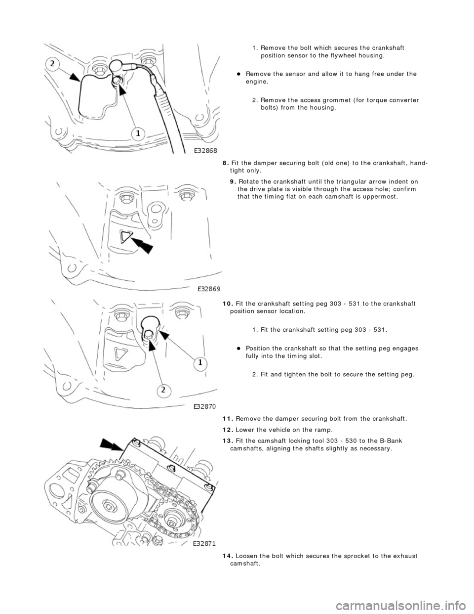
1. Remove the bolt which secures the crankshaft position sensor to the flywheel housing.
Remove the sensor and allow it to hang free under the
engine.
2. Remove the access grommet (for torque converter bolts) from the housing.
8. Fit the damper securing bolt (old one) to the crankshaft, hand-
tight only.
9. Rotate the crankshaft until the triangular arrow indent on
the drive plate is visible thro ugh the access hole; confirm
that the timing flat on ea ch camshaft is uppermost.
10. Fit the crankshaft setting peg 303 - 531 to the crankshaft
position sensor location.
1. Fit the crankshaft setting peg 303 - 531.
Position the crankshaft so that the setting peg engages
fully into the timing slot.
2. Fit and tighten the bolt to secure the setting peg.
11. Remove the damper securing bolt from the crankshaft.
12. Lower the vehicle on the ramp.
13. Fit the camshaft locking tool 303 - 530 to the B-Bank
camshafts, aligning the shafts slightly as necessary.
14. Loosen the bolt which secures the sprocket to the exhaust
camshaft.
Page 883 of 2490
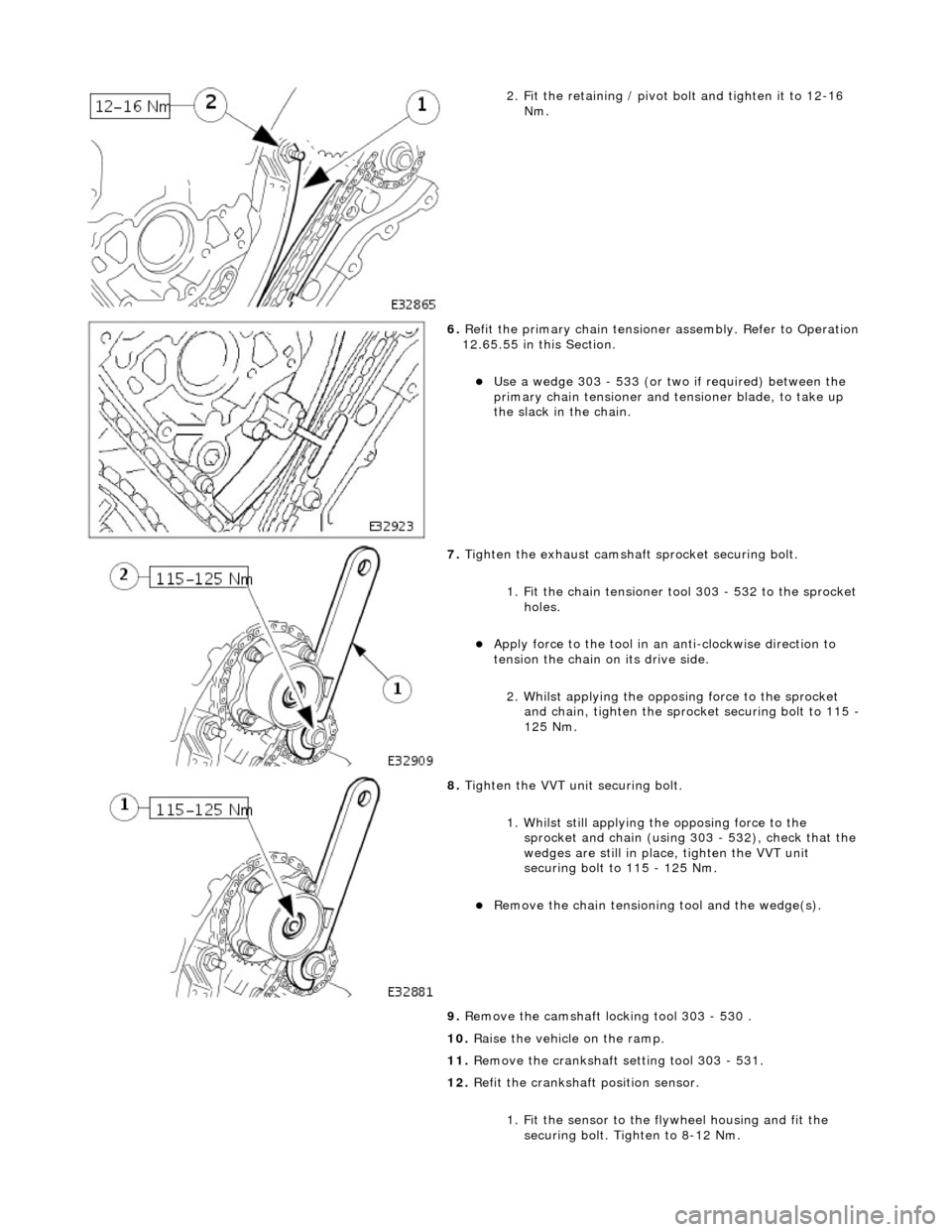
2. Fit the retaining / pivot bolt and tighten it to 12-16 Nm.
6. Refit the primary chain tensione r assembly. Refer to Operation
12.65.55 in this Section.
Use a wedge 303 - 533 (or two if required) between the
primary chain tensioner and te nsioner blade, to take up
the slack in the chain.
7. Tighten the exhaust camshaft sprocket securing bolt.
1. Fit the chain tensioner tool 303 - 532 to the sprocket holes.
Apply force to the tool in an anti-clockwise direction to
tension the chain on its drive side.
2. Whilst applying the opposing force to the sprocket and chain, tighten the sprock et securing bolt to 115 -
125 Nm.
8. Tighten the VVT unit securing bolt.
1. Whilst still applying the opposing force to the
sprocket and chain (using 303 - 532), check that the
wedges are still in place, tighten the VVT unit
securing bolt to 115 - 125 Nm.
Remove the chain tensioning tool and the wedge(s).
9. Remove the camshaft locking tool 303 - 530 .
10. Raise the vehicle on the ramp.
11. Remove the crankshaft setting tool 303 - 531.
12. Refit the crankshaft position sensor.
1. Fit the sensor to the fl ywheel housing and fit the
securing bolt. Tighten to 8-12 Nm.
Page 886 of 2490
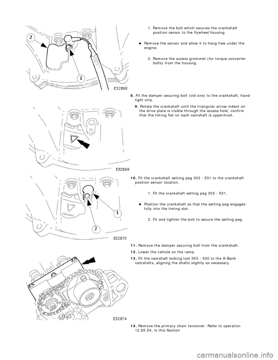
1. Remove the bolt which secures the crankshaft position sensor to the flywheel housing.
Remove the sensor and allow it to hang free under the
engine.
2. Remove the access grommet (for torque converter bolts) from the housing.
8. Fit the damper securing bolt (old one) to the crankshaft, hand-
tight only.
9. Rotate the crankshaft until the triangular arrow indent on
the drive plate is visible thro ugh the access hole; confirm
that the timing flat on ea ch camshaft is uppermost.
10. Fit the crankshaft setting peg 303 - 531 to the crankshaft
position sensor location.
1. Fit the crankshaft setting peg 303 - 531.
Position the crankshaft so that the setting peg engages
fully into the timing slot.
2. Fit and tighten the bolt to secure the setting peg.
11. Remove the damper securing bolt from the crankshaft.
12. Lower the vehicle on the ramp.
13. Fit the camshaft locking tool 303 - 530 to the A-Bank
camshafts, aligning the shafts slightly as necessary.
14. Remove the primary chain tens ioner. Refer to operation
12.65.54, in this Section
Page 889 of 2490
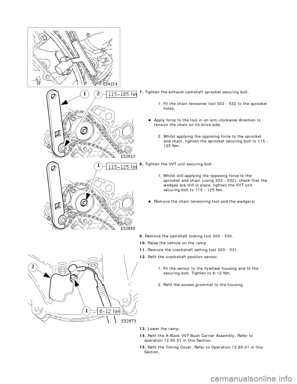
7. Tighten the exhaust camshaft sprocket securing bolt.
1. Fit the chain tensioner tool 303 - 532 to the sprocket holes.
Apply force to the tool in an anti-clockwise direction to
tension the chain on its drive side.
2. Whilst applying the opposing force to the sprocket and chain, tighten the sprock et securing bolt to 115 -
125 Nm.
8. Tighten the VVT unit securing bolt.
1. Whilst still applying the opposing force to the
sprocket and chain (using 303 - 532), check that the
wedges are still in place, tighten the VVT unit
securing bolt to 115 - 125 Nm.
Remove the chain tensioning tool and the wedge(s).
9. Remove the camshaft locking tool 303 - 530.
10. Raise the vehicle on the ramp.
11. Remove the crankshaft setting tool 303 - 531.
12. Refit the crankshaft position sensor.
1. Fit the sensor to the fl ywheel housing and fit the
securing bolt. Tighten to 8-12 Nm.
2. Refit the access grommet to the housing.
13. Lower the ramp.
14. Refit the A-Bank VVT Bush Carrier Assembly. Refer to
operation 12.65.51 in this Section.
15. Refit the Timing Cover. Refer to Operation 12.65.01 in this
Section.
Page 896 of 2490
Engine - Engine
Removal
Removal
Special Tool(s)
Engine Lifting Brackets
303-536
Quick Fit Connector Release Tool
310-044
Quick Fit Connector Release Tool
310-054
Quick Fit Connector Release Tool
303-623
Fuel Injection Pressure Test Equipment
310-058
1. Park the vehicle on a four post ramp, over which, an overhead
lifting crane is available, and set the gear selector to 'N'.
The crane should be rated at a minimum of 500 kg Safe
Working Load and have suffici ent fore and aft movement
to traverse the engine assemb ly clear of the vehicle.
Do not apply the handbrake, but use wedges to chock one
wheel to prevent movement of the vehicle.
2. Open the engine compartment and fit paintwork protection
sheets.
3. Disconnect the batt ery ground cable.
Remove the battery cover.
Page 930 of 2490
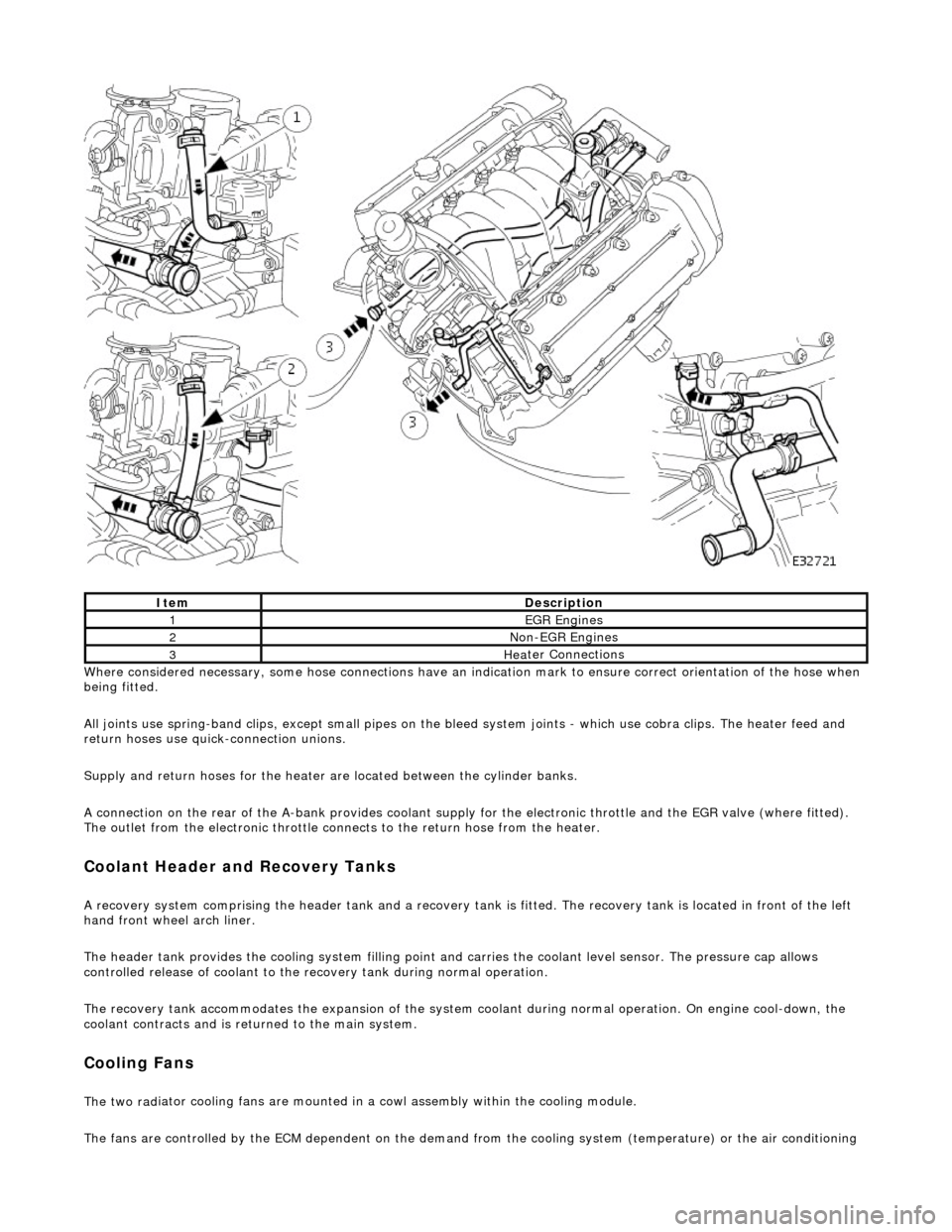
Whe r
e considered necessary, some hose conn
ections have an indication mark to ensure correct orientation of the hose when
being fitted.
All joints use spring-band clips, except small pipes on the bleed system joints - which use cobra clips. The heater feed and
return hoses use quick-connection unions.
Supply and return hoses for the heater are located between the cylinder banks.
A connection on the rear of the A-bank provides coolant supply for the electronic throttle and the EGR valve (where fitted).
The outlet from the electronic throttle connects to the return hose from the heater.
Cool
ant Header and Recovery Tanks
A recovery system comp
rising the header tank
and a recovery tank is fitted. The recove ry tank is located in front of the left
hand front wheel arch liner.
The header tank provides the cooling system filling point and carries the coolant level sensor. The pressure cap allows
controlled release of coolant to the re covery tank during normal operation.
The recovery tank accommodates the expansion of the system coolant during normal operation. On engine cool-down, the
coolant contracts and is returned to the main system.
Coo lin
g Fans
The two
rad
iator cooling fans are mounted in
a cowl assembly within the cooling module.
The fans are controlled by the ECM dependent on the demand fr om the cooling system (temperature) or the air conditioning
ItemDescrip
tion
1EGR
E
ngines
2Non
-
EGR Engines
3Hea
ter Connections
Page 1066 of 2490
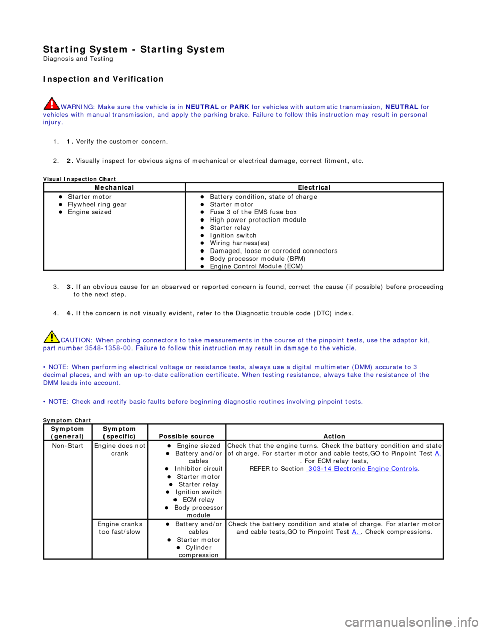
Starting System - Starting System
Diagn
osis and Testing
I
n
spection and Verification
W
A
RNING: Make sure
the vehicle is in NEUTRAL or PARK for vehicles with au tomatic transmission, NEUTRAL for
vehicles with manual transmissi on, and apply the parking brake. Failure to foll ow this instruction may result in personal
injury.
1. 1. Verify the customer concern.
2. 2. Visually inspect for obvious signs of mechanical or electrical damage, correct fitment, etc.
Vi
sual Inspection Chart
3.
3. If an obvi
ous cause for an observed or
reported concern is found, correct th e cause (if possible) before proceeding
to the next step.
4. 4. If the concern is not visually evident, refer to the Diagnostic trouble code (DTC) index.
CAUTION: When probing connectors to take measurements in the course of the pinpoint tests, use the adaptor kit,
part number 3548-1358-00. Failure to follow this in struction may result in damage to the vehicle.
• NOTE: When performing electrical voltag e or resistance tests, always use a digital multimeter (DMM) accurate to 3
decimal places, and with an up-t o-date calibration certificate. When testing resistance, always take the resistance of the
DMM leads into account.
• NOTE: Check and rectify basic faults before beginning diagnostic ro utines involving pinpoint tests.
Sym
ptom Chart
MechanicalElectrical
Starte
r motor
Flywheel
ring gear
Engine
s
eized
Batter
y condition, state of charge
Starte
r motor
F
u
se 3 of the EMS fuse box
High
power protec ti
on module
Starter relay Ignition switc
h
W
i
ring harness(es)
Damaged, loose or corroded connector
s
Body processor module (B
PM)
Engine
C
ontrol Module (ECM)
Sy
m
ptom
(
gene r
al)
Sy
m
ptom
(specific)
Possib l
e source
Acti
o
n
No
n
-Start
Engine does
not
crankEngine s
iezed
Batt
ery and
/or
cables
Inhibitor circuit St arte
r motor
Starter relay Ignition switc
h
ECM relay Body processor
modu le
Check that
the engine turns. Check the battery condition and state
of charge. For starter motor and ca ble tests,GO to Pinpoint Test A.
. For ECM relay
tests,
REFER to Section 303
-14
Electronic Engine Controls
.
Engine
c
ranks
too fast/slow
Batt ery and
/or
cables
St arte
r motor
Cy
linder
com
pression
Check the battery con
dition
and st
ate of charge. For starter motor
and cable tests,GO to Pinpoint Test A.
. Chec
k compressions.