Page 1345 of 2490

Automatic Transmission/Transaxle - 4.0L NA V8 - AJ27/3.2L NA V8 - AJ26
- Extension Housing O-Ring Seal
In-vehicle Repair
Removal
1. Select N position.
2. Raise the vehicle for access.
3. Remove the front muffler, 30.10.18.
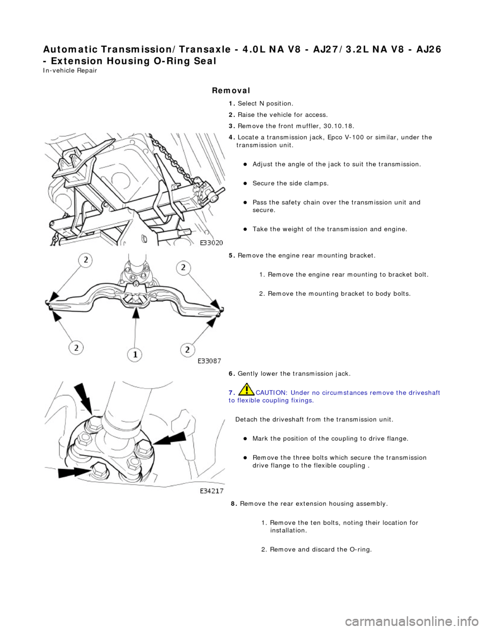
4. Locate a transmission jack, Epco V-100 or similar, under the
transmission unit.
Adjust the angle of the jack to suit the transmission.
Secure the side clamps.
Pass the safety chain over the transmission unit and
secure.
Take the weight of the transmission and engine.
5. Remove the engine rear mounting bracket.
1. Remove the engine rear mounting to bracket bolt.
2. Remove the mounting bracket to body bolts.
6. Gently lower the transmission jack.
7. CAUTION: Under no circumstan ces remove the driveshaft
to flexible coupling fixings.
Detach the driveshaft fro m the transmission unit.
Mark the position of the coupling to drive flange.
Remove the three bolts which secure the transmission
drive flange to the flexible coupling .
8. Remove the rear extension housing assembly.
1. Remove the ten bolts, noting their location for installation.
2. Remove and discard the O-ring.
Page 1377 of 2490
16. Remove the engine rear mounting bracket.
1. Remove the engine rear mounting to bracket bolt.
2. Remove the mounting bracket to body bolts.
17. Detach the driveshaft from th e transmission drive flange.
If the transmission is to be refitted, mark the position of
the coupling to drive flange.
17. CAUTION: Under no circ umstances remove the
driveshaft to flexible coupling fixings.
Remove the transmission drive flange to flexible coupling
three fixings.
18. Lower the transmission unit by carefully releasing the engine
support beam and by loweri ng the transmission jack.
19. Detach the gear selector cable from the transmission unit.
1. Remove the selector cable ball pin to selector lever nut.
2. Remove the selector cable to transmission casing bolts.
20. Disconnect the transmission harness multiplug.
1. Rotate the locking lever to release.
2. Disconnect the multiplug.
Page 1380 of 2490
31.
NOTE: Viewed from the rear of the vehicle.
Remove the six remaining transmission case to cylinder block
bolts.
32. NOTE: Do not allow the converter to detach from the
transmission.
Remove the transmission / converter assembly from the
vehicle.
Lower the transmission jack and remove the transmission,
ensuring that the torque co nverter spigot disengages
cleanly from the engine.
33. If appropriate, fit retainin g straps to the converter /
transmission assembly.
Page 1386 of 2490
13. Refit the rotary switch and tighten the two screws to the
specified torque figure. Locate the switch harness into the clips.
14. Connect the fluid cooler pipes to the transmission.
Remove the blanking plugs.
Fit new O-ring seals.
Tighten the union nuts to the specified torque figure.
15. Remove the engine support beam.
Remove both engine lifting brackets 303 - 536.
16. Refit the RH downpipe catalytic converter. Refer to Operation
17.50.09 and 17.50.10
17. Refit the front muffler. Refer to Operation 30.10.18.
18. Refit the LH downpipe catalytic converter. Refer to Operation
17.50.09
19. Lower the vehicle on the ramp.
Page 1390 of 2490

Stator, intermediate and output shafts. Three epicyclic geartrains. Six multi-disc clutch/brake packs. Two freewheels (One-way clutches). Hydraulic pump. Parking lock assembly. Electro-hydraulic control unit. Internal harness and 13 pin connector with bayonet lock.
Hydraulic pump
This engine driven pump is located at the front of the transmission casing and provides pressure for the hydraulic
functions.
Supplies fluid under pressure to the torq ue converter, geartrain, electro-hydraulic control unit and the lubrication
circuit.
Draws fluid from the fluid pa n below the transmission casing, through a filter.
Parking lock
This component prevents movement of th e vehicle by engaging a fixed pawl with the parking lock gear located on the
output shaft. The pawl is engaged by movi ng the gear selector lever to the park (P) position.
Electro-hydraulic control unit
This unit, mounted in the transmission lower case, converts signals, mechanical from the J-gate and electrical from the
TCM, into hydraulic functions.
The following components ar e assembled to the unit:
Selector valve. Shift plate. Control valve - modulating pressure. Control valve - shift pressure. Solenoid valve 1 <-> 2 and 4 <-> 5 shift. Solenoid valve 3 <-> 4 shift. Solenoid valve 2 <-> 3 shift. Solenoid valve - converter lock-up. Speed sensors (2). Temperature sensor.
Speed sensors
There are two speed sensors within the transmission assembly which provide input to the TCM. These inputs, when used in
conjunction with CAN data relative to engine speed (from ECM) and road speed (from ABS), are used to electronically
control the transmission.
Temperature sensor
The output from this sensor allows the TCM to compensate for the affect of fluid temperature on shift time and quality
Control Systems
Hydraulic Control
The selector valve is operated directly by the J-gate and directs fluid flow for P R N D.
Of the four solenoid valves, 3 control shifts and 1 controls converter lock-up. One control valve controls modulating pressure
and the other shift pressure.
Regulating valves are used to maintain/control pressure for lu brication, normal operating functions, and the supply to the
control valves and shift valves.
Page 1436 of 2490
Automatic Transmission/Transaxle - 4.0L SC V8 - AJ26 - Main Control
Valve Body
In-vehicle Repair
Removal
• NOTE: This procedure will not remove re sidual fluid from the torque converter.
1. Disconnect the battery ground lead.
2. Raise the vehicle for access.
3. Remove the RH catalytic converter; refer to Operation
17.50.10.
4. Remove the harness heatshield lower fixing.
Remove the screw heatshield / fluid pan clamp.
5. Remove the harness heatshield.
Pull the heatshield from under the clip.
6. Disconnect the transmission link harness connector.
1. Release the locking lever.
7. Release the (transmission case mounted) female connector.
Remove the (center) retaining bolt.
Page 1443 of 2490
Automatic Transmission/Transaxle - 4.0L SC V8 - AJ26 - Transmission
Internal Wiring Harness Electr ical Connector O-Ring Seals
In-vehicle Repair
Removal
1. Disconnect the batt ery ground cable.
2. Open the engine compartment and fit paint protection sheets.
3. Raise the vehicle for access.
4. WARNING: TRANSMISSION FLUID MAY CAUSE SEVERE
BURNS, ENSURE THAT ALL SAFET Y PROCEDURES ARE OBSERVED
AND THAT THE RECEPTACLE FOR WASTE HAS SUFFICIENT
CAPACITY.
Drain the transmission fluid.
Carefully remove the drain pl ug and discard the sealing
washer.
5. Remove the harness heatshield lower fixing.
Remove the screw heatshield / fluid pan clamp.
6. Remove the harness heatshield.
Pull the heatshield from under the clip.
7. Disconnect the transmission link harness connector.
1. Release the locking lever on the guide bush and disconnect the harness connector.
Page 1451 of 2490
20. Lower the transmission unit.
21. Detach the gear selector cable from the transmission unit.
1. Remove the selector cable ball pin to selector lever nut.
2. Lower the transmissi on lift for access.
3. Remove the selector cable to transmission casing bolts.
22. Release the transmission ha rness multiplug bracket.
1. Remove the two bolts which secure the bracket to the
transmission case, noting that one bolt also retains
the dipstick tube.
23. Disconnect the fluid cooler upper pipe.
Remove the bolt which secures the pipe to the cylinder
block and remove the bracket.
Remove the 'banjo' bolt.