Page 1394 of 2490

Range Selection
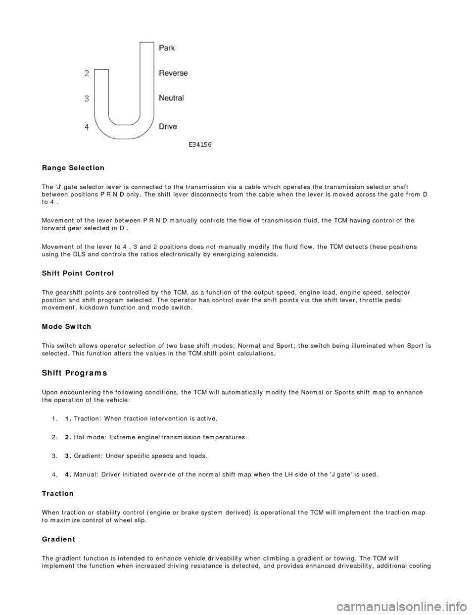
The 'J' gate selector lever is connected to the transmission via a cable which operates the transmission selector shaft
between positions P R N D only. The shift lever disconnects from the cable when the lever is moved across the gate from D
to 4 .
Movement of the lever between P R N D manu ally controls the flow of transmission fluid, the TCM having control of the
forward gear selected in D .
Movement of the lever to 4 , 3 and 2 positions does not manu ally modify the fluid flow, the TCM detects these positions
using the DLS and controls the ratios electronically by energizing solenoids.
Shift Point Control
The gearshift points are controlled by the TCM, as a function of the output speed, engine load, engine speed, selector
position and shift program selected. The operator has control over the shift points via the shift lever, throttle pedal
movement, kickdown function and mode switch.
Mode Switch
This switch allows operator selection of two base shift modes; Normal and Sport; th e switch being illuminated when Sport is
selected. This function alters the values in the TCM shift point calculations.
Shift Programs
Upon encountering the following conditions, the TCM will auto matically modify the Normal or Sports shift map to enhance
the operation of the vehicle:
1. 1. Traction: When traction intervention is active.
2. 2. Hot mode: Extreme engine/transmission temperatures.
3. 3. Gradient: Under specific speeds and loads.
4. 4. Manual: Driver initiated override of the normal shif t map when the LH side of the 'J gate' is used.
Traction
When traction or stability control (engine or brake system de rived) is operational the TCM will implement the traction map
to maximize control of wheel slip.
Gradient
The gradient function is intended to enhance vehicle drivea bility when climbing a gradient or towing. The TCM will
implement the function when increased driving resistance is de tected, and provides enhanced driveability, additional cooling
Page 1836 of 2490

System Self-test
Control Panel Interrogation Procedure
The control panel has a self-diagnosis feature, and is capable of displaying and clearing stored fault codes.
Climate control is an integrated system, therefore it is recommended that the PDU is used for fault diagnosis. The fault
codes displayed with the control panel self -diagnosis feature are not as comprehensive as those of the PDU. The PDU will
display the relevant fault code, fault co de description and information of the system peripherals at the time the fault
occurred.
Fault Code Extraction and Deletion Procedure
Error information is stored in the A/CCM up to a maximum of 5 faults. Should a sensor fault occur there will be an audible
beep and the message Er will be displayed on the control panel display for 5 seco nds after ignition on. Please note that this
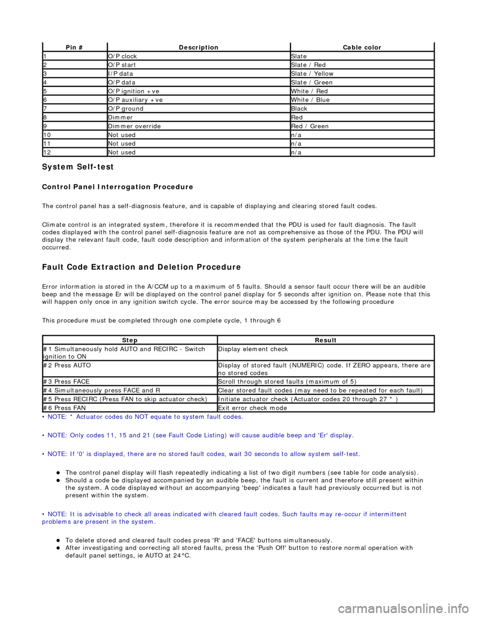
will happen only once in any ignition switch cycle. The error source may be accessed by the following procedure
This procedure must be completed through one complete cycle, 1 through 6
• NOTE: * Actuator codes do NOT equate to system fault codes.
• NOTE: Only codes 11, 15 and 21 (see Fault Code List ing) will cause audible beep and 'Er' display.
• NOTE: If '0' is displayed, there are no stored faul t codes, wait 30 seconds to allow system self-test.
The control panel display will flash repeatedly indicating a list of two digit numbers (see table for code analysis). Should a code be displayed accompanied by an audible beep, the fault is current and therefore still present within
the system. A code displayed without an accompanying 'bee p' indicates a fault had previously occurred but is not
present within the system.
• NOTE: It is advisable to check all areas indicated with cleared fault codes. Such faults may re-occur if intermittent
problems are present in the system.
To delete stored and cleared fault codes press 'R' and 'FAC E' buttons simultaneously. After investigating and correcting all stored faults, press the 'Push Off' button to restore normal operation with
default panel settings, ie AUTO at 24°C.
Pin #DescriptionCable color
1O/P clockSlate
2O/P startSlate / Red
3I/P dataSlate / Yellow
4O/P dataSlate / Green
5O/P ignition +veWhite / Red
6O/P auxiliary +veWhite / Blue
7O/P groundBlack
8DimmerRed
9Dimmer overrideRed / Green
10Not usedn/a
11Not usedn/a
12Not usedn/a
StepResult
#1 Simultaneously hold AU TO and RECIRC - Switch
ignition to ONDisplay element check
#2 Press AUTODisplay of stored fault (NUMERIC) code. If ZERO appears, there are
no stored codes
#3 Press FACEScroll through stored faults (maximum of 5)
#4 Simultaneously press FACE and RClear stored fault codes (may need to be repeated for each fault)
#5 Press RECIRC (Press FAN to skip actuator check)Initiate actuator check (Actuator codes 20 through 27 * )
#6 Press FANExit error check mode
Page 1977 of 2490

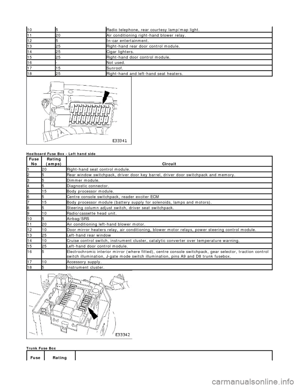
Heelboard Fuse Box - Left hand side
Trunk Fuse Box
105Radio telephone, rear courtesy lamp/map light.
1120Air conditioning right-hand blower relay.
125In-car entertainment.
1325Right-hand rear door control module.
1425Cigar lighters.
1525Right-hand door control module.
16-Not used.
1715Sunroof.
1825Right-hand and left-hand seat heaters.
Fuse NoRating
(amps)Circuit
120Right-hand seat control module.
25Rear window switchpack, driver door key ba rrel, driver door switchpack and memory.
35Dimmer module.
45Diagnostic connector.
515Body processor module.
65Centre console switchpack, reader exciter ECM
715Body processor module (battery supply for solenoids, lamps and motors).
85Steering column adjust switch, driver seat switchpack.
910Radio/cassette head unit.
105Airbag/SRS
1120Air conditioning left-hand blower motor.
1210Door mirror heaters relay, air conditioning, blow er motor relays, power steering control module.
1325Left-hand rear window
1410Cruise control switch, instrument cluster, catalytic converter over temperature warning.
1525Left-hand door control module.
165Electrochromic interior mirror (where fitted), centre console switchpack, gear selector, traction control
switch illumination, J-gate mode switch illumination, pins A9 and D8 trunk fusebox.
1710Accessory supply.
185Instrument cluster.
Fuse Rating
Page 2012 of 2490
Parts List
The Center Console Switch Module comprises the integral switches identified in the illustration above. All switches with the
exception of the Traction Control Switch are connected to BPM inputs. The Traction Control Switch is connected to an ABS
unit input.
ItemPart NumberDescription
1—Central locking switch
2—Valet switch
3—Left hand seat heater switch (where fitted)
4—Right hand seat heater switch (where fitted)
5—Traction control switch (where fitted)
6—Hazard warning switch
Page:
< prev 1-8 9-16 17-24