1998 JAGUAR X308 traction control
[x] Cancel search: traction controlPage 525 of 2490

2—Ignition ampl
ifier failure
3—Crankin
g
4—Camshaft position
5—Mass ai
r flow
6—Inta
ke air temperature
7—Coo
lant temperature
8—Exhaus
t gas oxygen content
9—Knock
sensor
10—Power supply
11—Cl
imate control compressor
12—Cli
mate control system pressure
13—Traction contr
ol
14—Park / neutral
switch
15—Throttle pedal demand
16—Thro
ttle position
17—Securi
ty mode
ECM In
puts
It
em
Par
t Number
De
scription
1—Engine
speed
Page 527 of 2490
E
ngine Management System Components
Electronic Throt
tle
The
electronic throttle assembly, in resp
onse to signals from both the driver and the ECM, adjusts idle speed, sets the
throttle valve to the position requested by the driver's accelerator / throttle pedal, cruise and traction control, power
limitation and catalyst warm-up.
Mass
Air Flow Meter
The sensor i
s located in the air flow mete
r assembly and outputs an analogue voltag e to the ECM. This sensor measures air
flow into the engine inlet system and is calibrated to measure kg / hour.
In
take Air Temperature
Th
e intake air temperature sensor is loca
ted in the air flow meter assembly and outputs an analogue voltage to the ECM.
The ECM will substitute a default value eq ual to 50°C should this sensor fail.
Fuel Injectors
The eigh
t bottom fed fuel injectors are located in the fuel rails. Th
e fuel injectors are electromagnetic solenoid valves
controlled by the ECM. The pulse time for the injector combined with the fuel pr essure determines the volume of fuel
injected to the manifold.
Fue
l Delivery
The fu
el pump provides fuel to the fuel rail where the circulat
ing pressure is controlled by a pressure regulator valve; excess
fuel is returned to the fuel tank.
The pressure regulator valve is controlled by manifold depression so that fuel delivery pressure is maintained at
approximately 3 bar above manifold pressure.
Fuel Pump
Relay
The ECM controls thi
s component for normal
engine running. The security system may disable this relay via communication
with the ECM.
Fuel Lev
el Sensing
The tank fuel
is measured by the fuel le
vel sensor . This signal is used by the ECM as an in put to certain diagnostics.
Eva
porative Valve
Excess vapour
formed in the fuel tank is
absorbed into the evaporative emission pu rge control canister. While the engine is
running, the fuel absorbed in the canister is gradually purged back into the engine. The rate of purging is governed by
engine operating conditions and vapour concentration level. Operating conditions which affect the purge rate are:
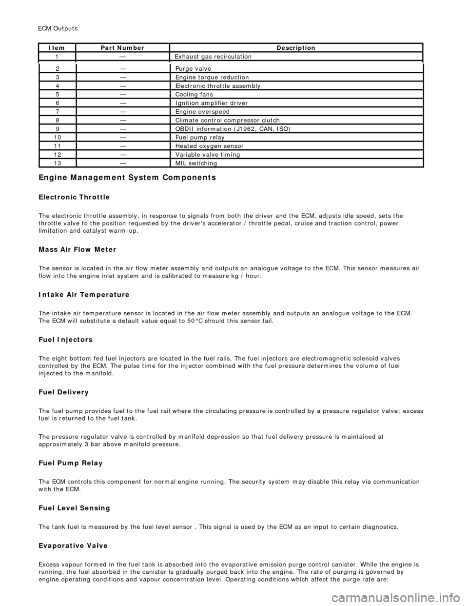
2—Purge
valve
3—Engine
torque reduction
4—E
lectronic throttle assembly
5—Coo
ling fans
6—Ignition amplifier driver
7—Engine overspeed
8—Cli
mate control compressor clutch
9—O
BDII information (J1962, CAN, ISO)
10—F
uel pump relay
11—Heat
ed oxygen sensor
12—Vari
able valve timing
13—MIL sw
itching
ECM Out
puts
It
em
Par
t Number
De
scription
1—Exhaus
t gas recirculation
Page 528 of 2490
Speed an
d load
Coo
l
ant temperature
Ti
me el
apsed from start up
Cl
osed l
oop fuelling
Determination of the vapour concentration is made by stepped opening of the EVAP valve and subsequent monitoring of the
fuelling correction. This function is performed prior to purging, so that at the onse t of purging the EVAP valve can be set to
the optimum position. Should the ECM be unable to determine the concentration before purging, a default value is
employed, which is then modified whilst purging is in progress.
When the purging process is operational th e ECM modifies the basic fuelling calculation to maintain the correct air / fuel
ratio.
Purging is inhibited during fuel cut-off and stability / traction control intervention.
Coolant Temperature Sen
sor
Th
e
sensor outputs a voltage to the ECM which decreases as temperature increases.
Cooling Fans
In response to engi
ne coolant temperat
u
re and climate control system demand, the ECM will energize the cooling fans.
Climate Control Compressor
The E
C
M will allow the compressor clutch to be engaged if th
e engine temperature and load demand are normal. Should the
driver require maximum engine powe r or the coolant temperature be high, the request will be denied.
Cranking Signal
The ECM reacts to a signal fr
om th
e Body Processor Module (BPM) when the starter motor relay is energi
zed. This signal is
used to trigger starting, fu el and ignition strategies.
Engine Speed and Cranksh
aft Position
Engine
speed and cran
k position are moni
tored by a sensor which is mounted on the cylinder block (flywheel housing)
behind the crankshaft drive plat e. It indicates rotational speed to the ECM in the form of 12 pulses per crank revolution.
Engine speed is used for synchronization of fuel an d ignition systems, as well as other functions.
Camshaft Position
The ca
mshaft position sensor is mounted at
the rear of Bank 2 cylinder head on the inlet side and provides one signal every
720 degrees of crankshaft rotation. The signal, in conjunction with the signal from the crankshaft position sensor, indicates
to the ECM that the piston of cylinder 1A is approaching TDC on the compression stroke.
Variable Valve
Timing (Where Fitted)
By energi
si
ng a solenoid to allow the pass
age of pressurized oil on each of the inle t camshaft drives, the ECM can vary by a
single stepped amount, the relati ve timing of the inlet valves.
Ign
ition
Ignit
i
on spark is produced by
individual on-plug coil units.
There are two ignition amplifiers; module #1 drives coils 1A, 2B, 3B and 4A, whilst module #2 drives coils 1B, 2A, 3A and
4B. The ECM controls the amplifiers.
Page 1110 of 2490
2.2. Cruise
3. 3. Mechanica l
guard
4. 4. Fixed idle
5. 5. Redundancy
6. 6. Full authority
7. 7. Engine shut-down
Normal mode occurs when the EC M uses the mechanical and monitoring arrangem ent of the throttle valve to control throttle
opening. The ECM does not permit driver demand to be exceeded but it can be restricted to allow for such features as
stability / traction control, or engine power limitation.
The ECM determines engine idle speed by controlling the throttle valve motor to vary the blade angle between the non-
adjustable preset limits of the mechanic al guard and the throttle valve motor.
Cruise mode is engaged as a result of the ECM calculating and controlling the required throttle valve opening via the
vacuum system. When the driver releases the throttle pedal, the input shaft disengages from the mechanical guard or the
vacuum actuator pulls the guard away from th e throttle valve. The throttle pedal will feel light should it be pushed again to
accelerate (pressing the pedal further will re-engage the input shaft with the mechanical guard and restore normal feel).
The ECM utilizes sensors to monitor the relative positions of the mechanical guard and throttle valve and adjusts them to
maintain the set cruise speed.
Mechanical guard mode permits full mechanical operation of the throttle if the ECM detects that a problem has been
encountered with the throttle valve position sensor, dc motor, associated harnesses / connecto rs or the ECM.
Fixed idle mode occurs when any two of the three sensors (two input shaft sensors and the mechanical guard sensor) fail.
The ECM will assume values which represent a blade angl e of approximately 2,5° and 1200 rpm (unloaded) maximum
engine speed.
Redundancy mode occurs when any one of the three sensors (two input shaft sensors and the mechanical guard sensor)
fails. The operational pair will be deemed to be safe to co ntinue without intervention, but cruise will be inhibited.
Full authority mode is invoked when a mech anical guard failure occurs which indicates that the guard is stuck fully open.
The red warning lamp will be lit and road speed will be li mited to 120 kph.
Engine shut-down mode will occur followin g multiple failures, such as mechanical guard mode following full authority mode
(or vice versa) or the throttle blade sticks.
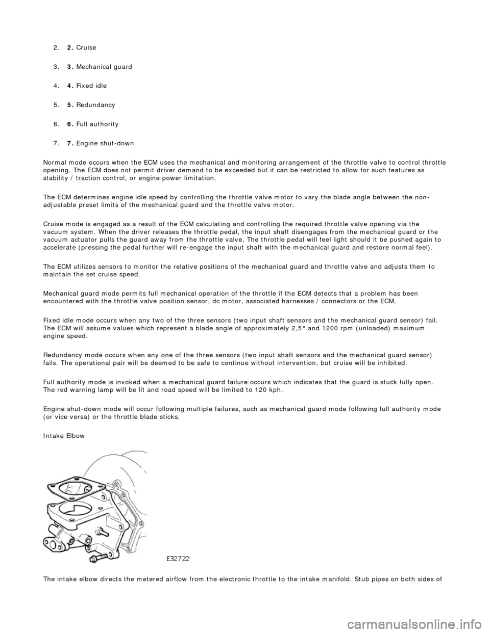
Intake Elbow
The intake elbow directs the metered airflow from the electronic throttle to the intake manifold. Stub pipes on both sides of
Page 1192 of 2490
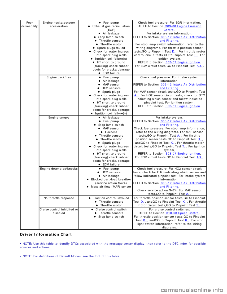
Driver Information
Chart
•
NOTE: Use this table to identify DTCs associated with the me
ssage center display, then refer to the DTC index for possible
sources and actions.
• NOTE: For definitions of Default Modes, see the foot of this table.
Poor
dr iveabilityEngine h e
sitates/poor
acceleration
Fue l
pump
Exhaus
t gas
recirculation
(EGR)
Air leakage Stop lamp swi t
ch
Throttl
e
sensors
Throttl
e
motor
Spark
plugs
fouled
Check f
o
r water ingress
into spark plug wells
Ignition coil fail
ure(s)
HT sh
o
rt to ground
(tracking) check rubber
boots for cracks/damage
ECM failu r
e
Check f
u
el pressure. For EGR information,
REFER to Section 303
-08 En gin
e Emission
Control.
F or i
ntake system information,
REFER to Section 303
-1 2
Intake Air Distribution
and F
ilt
ering
.
F or stop l
amp switch in
formation, refer to the
wiring diagrams. For throttle position sensor
tests,GO to Pinpoint Test D.
. Fo
r throttle motor
control circuit tests,GO to Pinpoint Test T.
. For
igni t
ion system,
REFER to Section 303
-07 En
gine Ignition
.
F or ECM
circuit tests,GO to Pinpoint Test
AD.
.
Engine backfiresFuel
pump
Air leakage MAF se
nsor
HO2 sensors
Spark plugs Check fo
r water ingress
into spark plug wells
HT sh o
rt to ground
(tracking) check rubber
boots for cracks/damage
Ignition coil fail
ure(s)
Chec
k fu
el pressure. For intake system
information,
REFER to Section 303
-12
Intake Air Distribution
and Filt
ering
.
F or MAF sensor ci
rcuit test
s,GO to Pinpoint Test
A.
. F or HO2 sensor
circui
t tests, check for DTC
indicating which sensor and follow indicated pinpoint test. For ignition system,
REFER to Section 303
-07 En
gine Ignition
.
Engine
s
urges
Air leakage
Fuel
pump
Stop lamp swit
ch
MAF s
e
nsor
Harness Throttl
e
sensors
Throttl
e
motor
Spark plugs
Check fo
r water ingress
into spark plug wells
HT sh o
rt to ground
(tracking) check rubber
boots for cracks/damage
ECM failu r
e
Fo
r
intake system,
REFER to Section 303
-1 2
Intake Air Distribution
and Filt
ering
.
Check fu
el pressure. For
stop lamp information,
refer to the wiring diagrams. For MAF sensor tests,GO to Pinpoint Test A.
. Fo
r throttle
position sensor tests,GO to Pinpoint Test D.
,
a n
dGO to Pinpoint Test
K.
. Fo
r throttle motor
circuit tests,GO to Pinpoint Test T.
. For ig
nition
system,
REFER to Section 303
-07 En
gine Ignition
.
F or ECM
circuit tests,GO to Pinpoint Test
AD.
.
Engine detonates/k
nocks
Fue
l
pump
HO2 sensors
Air leakage Blocked part-load breather
(s
ervice action S474)
Mass ai
r fl
ow (MAF) sensor
Chec
k fu
el pressure. Fo
r HO2 sensor circuit
tests, check for DTC indicating which sensor and
follow indicated pinpoint test. For intake system
information,
REFER to Section 303
-1 2
Intake Air Distribution
and Filt
ering
.
Check service action S474
. For MAF sensor
tests,GO to Pinpoint Test A.
.
No t
hrottle response
Traction contr
o
l invoked
Throttl
e
sensors
Throttl
e
motor
Fo
r th
rottle position sensor tests,GO to Pinpoint
Test D.
, andG O to Pinpoint
Test
K.
. Fo
r throttle
motor circuit tests,GO to Pinpoint Test T.
.
Cru i
se control inhibited or
disabled
Cru i
se control switch
Throttle
sensors
Stop lamp swit
ch
For cru
i
se control switches,
REFER to Section 310
-03
Speed Control
.
For th
rottle position sensor tests,GO to Pinpoint
Test D.
, andG O to Pinpoint
Test
K.
. For s t
op
light switch information, refer to the wiring diagrams.
Page 1271 of 2490
Controller Area Network (CAN)
The TCM is an integral part of the CAN system which facilitates the interchange of real-time data between control modules
and sensors. Please see section 303- 14 for a full description of CAN.
OBDII Interface
Data concerning OBDII related transmission failures is stored in the ECM for access via the J1962 socket.
System Functions
Range Selection
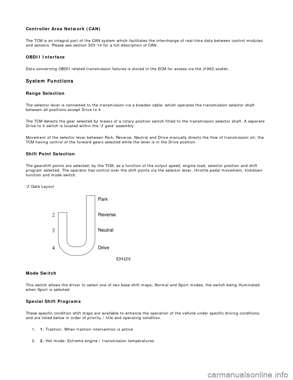
The selector lever is connected to the transmission via a bowden cable, which operates the transmission selector shaft
between all positions except Drive to 4 .
The TCM detects the gear selected by means of a rotary position switch fitted to the transmission selector shaft. A separate
Drive to 4 switch is located within the 'J' gate' assembly.
Movement of the selector lever between Park, Reverse, Neutral and Drive manually directs th e flow of transmission oil; the
TCM having control of the forward gears selected while the lever is in the Drive position.
Shift Point Selection
The gearshift points are selected, by the TCM, as a function of the output speed, engine load, selector position and shift
program selected. The operator has control over the shift points via the selector lever, throttle pedal movement, kickdown
function and mode switch.
'J' Gate Layout
Mode Switch
This switch allows the driver to select one of two base shift maps; Normal and Sport modes, the switch being illuminated
when Sport is selected.
Special Shift Programs
These specific condition shift maps are available to enhance the operation of the vehicle under specific driving conditions.
and are listed below in order of priority / title and operating condition.
1. 1. Traction: When traction intervention is active
2. 2. Hot mode: Extreme engine / transmission temperatures
Page 1272 of 2490
3.3. Gradient: Under specific speeds and loads
4. 4. Cruise: During cruise control
5. 5. Manual: Shift map when the LH side of the 'J gate' is used
Three specific condition shift maps have a higher priority than the two base shift maps and will intervene when appropriate
conditions prevail for traction, gradient or cruise.
When traction control (engine or brake system derived) is operational the TCM will implement the traction map to maximise
control of wheel slip.
The gradient maps are intended to enhance vehicle drivability when towing or climbing a gradient. The TCM will implement
the maps when increased driving resistan ce is detected and enhanced drivability, cooling and increa sed performance is
appropriate.
The cruise map is intended to minimize unwanted gearshifts and 'hunting' and is activated when cruising near to the set
speed, or resuming.
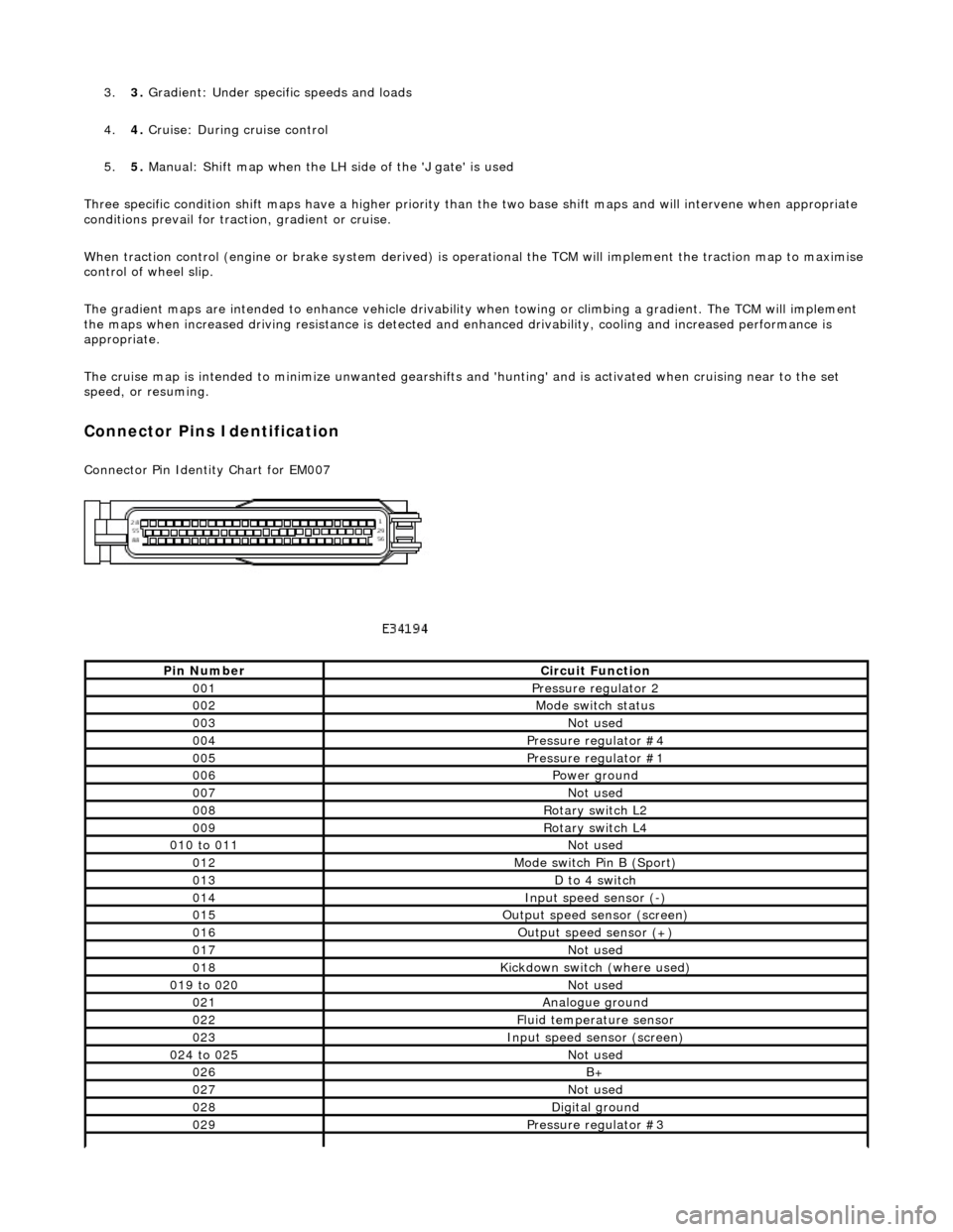
Connector Pins Identification
Connector Pin Identity Chart for EM007
Pin NumberCircuit Function
001Pressure regulator 2
002Mode switch status
003Not used
004Pressure regulator #4
005Pressure regulator #1
006Power ground
007Not used
008Rotary switch L2
009Rotary switch L4
010 to 011Not used
012Mode switch Pin B (Sport)
013D to 4 switch
014Input speed sensor (-)
015Output speed sensor (screen)
016Output speed sensor (+)
017Not used
018Kickdown switch (where used)
019 to 020Not used
021Analogue ground
022Fluid temperature sensor
023Input speed sensor (screen)
024 to 025Not used
026B+
027Not used
028Digital ground
029Pressure regulator #3
Page 1392 of 2490
CAN Input Signals
Traction status ABS malfunction ABS status Engine torque status Throttle position Accelerator pedal position Engine torque reduction confirmation Engine speed Engine coolant temperature Cruise status OBDII fault code clear request Throttle malfunction warning RED or AMBER All road wheel speeds Token for network status ECM Token for network status INST Token for network status ABS Diagnostic data in from external device (PDU)
Output Signals
Solenoid valve 1 <-> 2 and 4 <-> 5 shift Solenoid valve 2 <-> 3 shift Solenoid valve 3 <-> 4 shift Solenoid valve converter lock-up clutch Control valve - modulating pressure Control valve - shift pressure
CAN Output Signals
Engine torque reduction request MIL status (whether present DTC should operate MIL) Transmission input speed Transmission output speed Converter slip Kickdown status Gear position (actual) Gear position (selected) Gear selection fault Converter lock-up status Current selected shift map Transmission oil temperature Transmission malfunction Pecus flag (state of current TCM program) Target for next gear position Gear shift torque transfer progress at shift MIL status (response to activate the MIL relevant to a DTC) OBDII fault code clear acknowledgement Transmission DTCs (P codes) Token for network status TCM Diagnostic data out to external device (PDU)
Emergency Running (elect ronic limp-home mode)
The TCM constantly monitors the transmissi on for faults. In the event of a problem the TCM will adopt the limp-home mode, in which the gear currently held remains engaged, until P is selected. The modulati ng and shift pressures will increase to
maximum and converter lock-up will be inhibited.
Following the selection of P , the only ratios available will be 2 (irrespective of forward ratio manual selection) and R .
With the vehicle at rest, the procedure to manually select is as follows:
1. 1. Select P .