Page 1133 of 2490
Intake Air Distribution and Filtering - Su
percharger Outl
et Pipe Gasket
Re
moval and Installation
Remov
al
Installation
1.
R
emove supercharger outlet
duct; refer to 18.50.16.
1. Installation is a reversal of the removal procedure.
Page 1253 of 2490
E
lectronic Engine Controls - Knock
Sensor (KS) LH4.0L SC V8 - AJ26
Re
moval and Installation
Remov
al
Installation
1.
R
emove supercharger; refer to 18.50.15.
2. Remove knock sensor from engine.
De
tach connector and disconnect.
R
emove knock sensor.
1. Installation is a reversal of the removal procedure.
2. Tighten sensor to 31 - 41 Nm.
Page 1255 of 2490
E
lectronic Engine Controls - Knock
Sensor (KS) RH4.0L SC V8 - AJ26
Re
moval and Installation
Remov
al
Installation
1.
R
emove supercharger; refer to 18.50.15.
2. Remove knock sensor from engine.
De
tach connector and disconnect.
R
emove knock sensor.
1. Installation is a reversal of the removal procedure.
2. Tighten sensor to 31 - 41 Nm.
Page 1804 of 2490
Air Conditioning - Air Conditioning (A/C) Compressor
Removal and Installation
Removal
1. Disconnect battery ground cable (IMPORTANT, see SRO
86.15.19 for further information).
2. Recover refrigerant from air co nditioning system; refer to
82.30.30.
3. Remove supercharger drive belt (where fitted); refer to
18.50.08.
4. Remove front end accessory dr ive belt; refer to 12.10.40 or
(SC) 12.10.40.
5. NOTE: A commercially availa ble brake pipe clamp is
recommended. Do not over tighten.
Clamp power steering reservoir to pump feed hose.
6. Raise vehicle for access
7. NOTE: Position drain tin to collect the fluid when union nut is
released.
Disconnect steering rack hose from pump. 1. Release union nut.
2. Discard O-ring.
3. Install suitable blanking plugs.
8. Disconnect clutch harness connector from compressor.
1. Disconnect connector.
9. Disconnect lines from compressor.
Discard O-rings.
Install suitable blanking plugs.
Page 1894 of 2490

Generator and Regulator - Generator4.0L SC V8 - AJ26
Removal and Installation
Removal
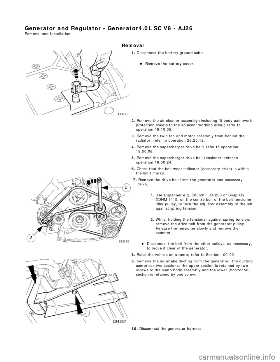
1. Disconnect the batt ery ground cable.
Remove the battery cover.
2. Remove the air cleaner assembly (including fit body paintwork
protection sheets to the adja cent working area); refer to
operation 19.10.05.
3. Remove the twin fan and moto r assembly from behind the
radiator; refer to operation 26.25.12.
4. Remove the supercharger drive belt; refer to operation
18.50.08.
5. Remove the supercharger driv e belt tensioner; refer to
operation 18.50.24.
6. Check that the belt wear indica tor (accessory drive) is within
the limit marks.
7. Remove the drive belt from the generator and accessory
drive,
1. Use a spanner e.g. Churchill JD-230 or Snap On XDHM 1415, on the centre bo lt of the belt tensioner
idler pulley, to turn the adju ster assembly to the left
against spring tension.
2. Whilst holding the tensioner against spring tension, remove the drive belt from the generator pulley.
Release the tensioner sl owly and remove the
spanner.
Disconnect the belt from the ot her pulleys, as necessary,
to move it clear of the generator.
8. Raise the vehicle on a ramp; refer to Section 100-02
9. Remove the air intake ducting fr om the generator. The ducting
comprises two sections; the upper section is retained by two
screws to the sump body assembly and the lower (horizontal)
section is retained by one screw.
10. Disconnect the generator harness.
Page:
< prev 1-8 9-16 17-24