Page 848 of 2490

Engine - Upper Oil Pan4.0L SC V8 - AJ26, 4.0L, Vehicles With:
Supercharger
In-vehicle Repair
Removal
Special Tool(s)
Installer/remover, Oil Filter
303-752
1. Disconnect the batt ery ground cable.
Remove the battery cover.
2. Open the engine compartment and fit paintwork protection
sheets.
3. Remove the engine compartmen t cover. Refer to Operation
76.16.01.
4. Remove the twin fan and motor assembly. Refer to Operation
26.25.12.
5. Remove the coolant outlet pipe . Refer to Operation 26.31.08.
6. Remove the supercharger driv e belt. Refer to Operation
18.50.08.
7. Remove the supercharger drive belt idler pulley. Refer to
Operation 18.50.09.
8. Remove the supercharger idle r pulley mounting bracket.
1. Remove the three bolts which secure the mounting
bracket.
2. Remove the mounting bracket.
9. Remove the supercharger driv e belt tensioner. Refer to
Operation 18.50.24.
10. Remove the timing cover and al l associated components, as
detailed in Operation 12.65.01.
11. Remove both front wheel and tyre assemblies. Refer to
Operation 74.20.05.
Page 1007 of 2490
W
ater Pump Pulley Vehicles Without: Supercharger
26.50.05
Removal
1. Open the engine compartment and fit paintwork protection sheets.
2
. Slacken the three screws which secure the water pump pulley.
3
.
C
AUTION:
When releasing the belt tension, never apply any torque in a clockwise direction to the pulley
centre bolt (left hand thread) as it could subsequently loosen.
Remove the drive belt from the generator and accessory drive. 1. Use a spanner e.g. Churchill JD-230 or Snap On XDHM 1415, on the centre bolt of the belt tensioner idler pulley, to turn the adjuster assembly to the left against spring tension.
Page 1009 of 2490
W
ater Pump Pulley Vehicles With: Supercharger
26.50.05
Removal
1. Open the engine compartment and fit paintwork protection sheets.
2. Remove the supercharger drive belt. Refer to Operation <<18.50.08>>.
3
. Slacken the three screws which secure the water pump pulley.
4
.
C
AUTION:
When releasing the belt tension, never apply any torque in a clockwise direction to the pulley
centre bolt (left hand thread) as it could subsequently loosen.
Page 1056 of 2490
Accessory Drive - Accessory Drive Belt
Idler Pulley4.0L SC V8 - AJ26
Re
mo
val and Installation
I
n
stallation
1.
Op
en the engine compartment and fit paintwork protection
sheets.
2. Remove the supercharger driv e belt, for access. Refer to
operation 18.50.08.
3. Remove the accessory drive belt for access. Refer to Operation
(12.10.40)
4. Re
move the idler pulley.
1. Remove the securing bolt from the idler pulley.
2. Remove the idler pulley.
1. Installation is the reverse of the removal procedure. Tighten
the pulley securing bolt to 53-69 Nm. Ensure that the belt is
correctly and squarely lo cated on each pulley.
2. Refit the supercharger drive belt. Refer to operation 18.50.08.
Page 1058 of 2490
Accessory Drive - Accessory
Drive Belt Tensioner4.0L SC V8 - AJ26
Re
mo
val and Installation
I
n
stallation
1.
Op
en the engine compartment and fit paintwork protection
sheets.
2. Remove the supercharger driv e belt, for access. Refer to
operation 18.50.08.
3. Remove the accessory drive belt for access. Refer to Operation
(12.10.40)
4. Remove t
he tensioner assembly, which includes the tensioner
pulley..
1. Remove the bolt whic h secures the tensioner
assembly to the engine.
2. Remove the tensioner assembly.
1. Installation is the reverse of the removal procedure. Tighten
the tensioner assembly securing bolt to 38-48 Nm. Ensure that
the belt is correctly and squa rely located on each pulley.
2. Refit the supercharger drive belt. Refer to operation 18.50.08.
Page 1059 of 2490

Ac
cessory Drive - Supercharger Belt
Re
moval and Installation
Remov
al
Installation
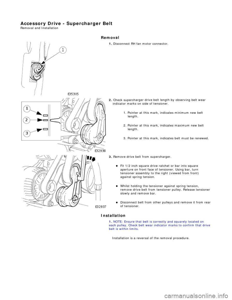
1.
Di
sconnect RH fa
n motor connector.
2. Check superch
arger dr
ive belt length by observing belt wear
indicator marks on side of tensioner.
1. Pointer at this mark, indicates minimum new belt length.
2. Pointer at this mark, indicates maximum new belt length.
3. Pointer at this mark, indi cates belt must be renewed.
3. R
emove drive belt from supercharger.
F
it 1/2 inch square drive ratchet or bar into square
aperture on front face of tensioner. Using bar, turn
tensioner assembly to the right (viewed from front)
against spring tension.
Wh
ilst holding the tensione
r against spring tension,
remove drive belt fr om tensioner pulley. Release tensioner
slowly and remove bar.
D
isconnect belt from
other pulleys and remove it from rear
of tensioner.
1. NOTE: Ensure that belt is correctly and squarely located on
each pulley. Check belt wear indicator marks to confirm that drive
belt is within limits.
Installation is a reversal of the removal procedure.
Page 1060 of 2490
Access
ory Drive - Supercharger Belt Idler Pulley
Re
mo
val and Installation
Remov
a
l
Installation
1.
Re
move supercharger drive belt; refer to 18.50.08.
2. Re
move supercharger drive belt idler pulley.
Re
mo
ve bolt .
R
e
move idler pulley.
1. Installation
is a reversal
of the removal procedure.
Page 1128 of 2490

Intake Air Distribution and Filtering - Supercharger
Remo
val and Installation
Remov
a
l
Installation
1. Disc onne
ct battery ground cable (IMPORTANT, see SRO
86.15.19 for further information).
2. Drain radiator coolant; refer to 26.10.01.
3. Remove air cleaner cover / intake assembly; refer to 19.10.30.
4. Remove throttle body; refer to 19.70.04.
5. Remove exhaust gas re-circulation valve (EGR) if installed;
refer to 17.45.01.
6. Remove throttle intake elbo w; refer to (SC) 19.70.28.
7. Remove supercharger outlet duct; refer to 18.50.16.
8. Remove coolant outlet pipe; refe r to operation (SC) 26.31.08.
9. Remove supercharger drive belt; refer to 18.50.08.
10. Disconnect remaining coolant hoses from charge air coolers.
Position pipes to facilitate removal
of supercharger.
Inst
al
l suitable blanking plugs.
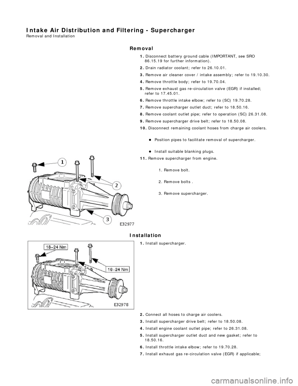
11 .
R
emove supercharger from engine.
1. Remove bolt.
2. Remove bolts .
3. Remove supercharger.
1. Inst al
l supercharger.
2. Connect all hoses to charge air coolers.
3. Install supercharger driv e belt; refer to 18.50.08.
4. Install engine coolant outlet pipe; refer to 26.31.08.
5. Install supercharger outlet du ct and new gasket; refer to
18.50.16.
6. Install throttle intake elbow; refer to 19.70.28.
7. Install exhaust gas re-circulation valve (EGR) if applicable;