1998 JAGUAR X308 fuel pressure
[x] Cancel search: fuel pressurePage 1013 of 2490
Fuel Ch
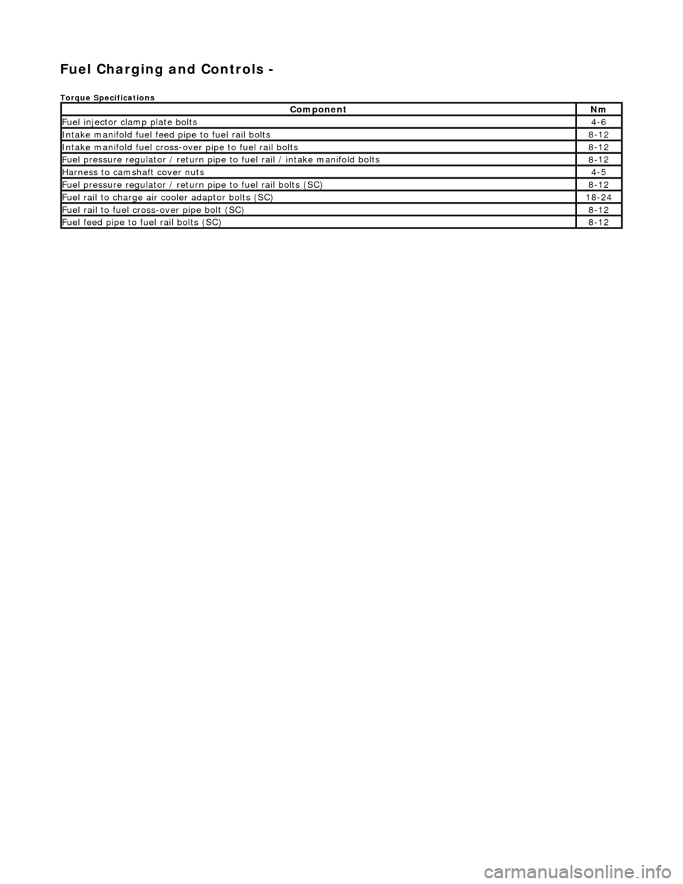
arging and Controls -
Torque Specific
ations
Com
ponent
Nm
Fue
l injector cl
amp plate bolts
4-
6
Inta
ke manifold fuel feed pipe to fuel rail bolts
8-
12
Inta
ke manifold fuel cross-over pipe to fuel rail bolts
8-
12
F
uel pressure regulator /
return pipe to fuel rail / intake manifold bolts
8-
12
Harness to
camshaft cover nuts
4-
5
F
uel pressure regulator / return
pipe to fuel rail bolts (SC)
8-
12
F
uel rail to charge air cooler adaptor bolts (SC)
18
-24
F
uel rail to fuel cross-over pipe bolt (SC)
8-
12
F
uel feed pipe to fuel rail bolts (SC)
8-
12
Page 1014 of 2490
Fuel Char
ging and Controls - Fuel Charging and Controls
Description an
d Operation
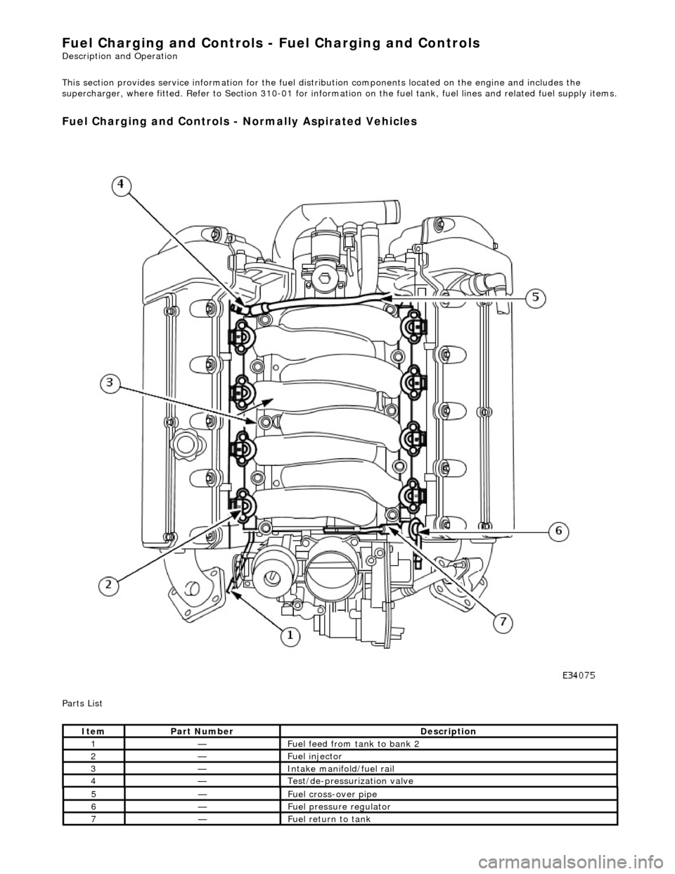
This section provides service informatio n for the fuel distribution components located on the engine and includes the
supercharger, where fitted. Refer to Section 310-01 for informatio n on the fuel tank, fuel lines and related fuel supply items.
Fuel Charging and Controls -
Normally Aspirated Vehicles
P
a
rts List
It
e
m
Par
t
Number
De
scr
iption
1—F
u
el feed from tank to bank 2
2—Fue
l
injector
3—Inta
k
e manifold/fuel rail
4—Te
st
/de-pressurization valve
5—F
u
el cross-over pipe
6—F
u
el pressure regulator
7—F
u
el return to tank
Page 1015 of 2490
Fuel D
istribution
Fuel is supplied to th
e engine
via eight fuel injectors (one pe r cylinder). The injectors are located in two fuel rails which r un
the length of each cylinder bank and ar e integral with the air intake manifold.
Fuel pumped from the tank enters a feed pipe at the rear of bank 2. Fuel flow is along bank 2 fuel rail, across the top front
of the engine (cross-over pipe) and through bank 1 fuel rail, the unused fuel re turning to the tank via a pressure regulator.
The fuel injectors are each controlled electrically from the engine control module (ECM).
A test valve is fitted to the cross-over pipe connecting the fu el rails at the front of the intake manifold. This valve allows the
fuel system to be depr essurized during servicin g and troubleshooting.
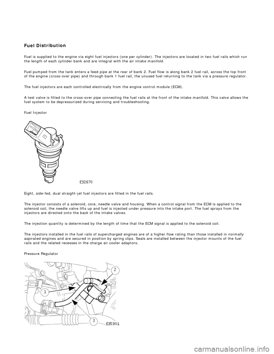
Fuel Injector
Eight, side-fed, dual straight-jet fuel injectors are fi tted in the fuel rails.
The injector consists of a solenoid, core, needle valve and ho using. When a control signal from the ECM is applied to the
solenoid coil, the needle valve lifts up and fuel is injected under pressure into the intake port. The fuel sprays from the
injectors are directed onto the back of the intake valves.
The injection quantity is determined by the length of time that the ECM signal is applied to the solenoid coil.
The injectors installed in the fuel rails of supercharged engines are of a higher flow rating than those installed in normally
aspirated engines and are secured in position by spring clips. Seals are instal led between the injector mounts of the fuel
rails and the related re cesses in the charge air cooler adaptors.
Pressure Regulator
Page 1016 of 2490
Pa
rts List
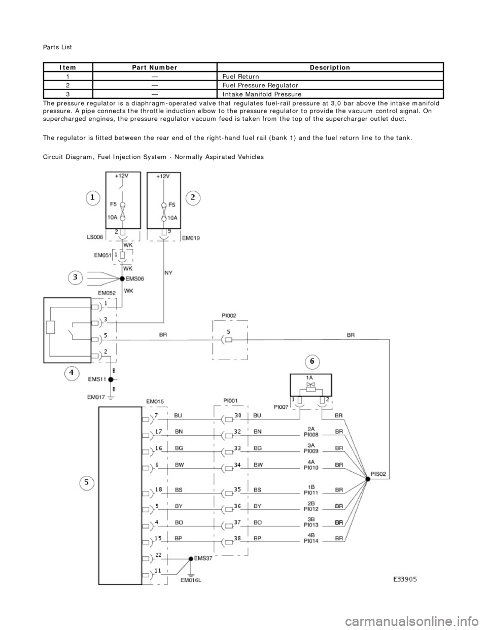
The pressure regulator is a diap hragm-operated valve that regula tes fuel-rail pressure at 3,0 bar above the intake manifold
pressure. A pipe connects the throttle induction elbow to the pressure regulator to provide the vacuum control signal. On
supercharged engines, the pressure regulator vacuum feed is taken from the top of the supercharger outlet duct.
The regulator is fitted between the rear end of the right-hand fuel rail (bank 1) and the fuel return line to the tank.
Circuit Diagram, Fuel Injection Syst em - Normally Aspirated Vehicles
Ite
m
Par
t
Number
De
scr
iption
1—F
u
el Return
2—F
u
el Pressure Regulator
3—Inta
k
e Manifold Pressure
Page 1019 of 2490
C
harge Air Cooler Adaptors
The charge
air cooler adaptors:
provi
de the interface between the charge air coolers and the cylinder heads
l
ocate the fuel ra
ils and injectors
For removal and installation refer to section 303-01.
Fuel R
ails
The plasti
c fuel rails locate in
the charge air cooler adaptors:
Bank 2 fuel rai
l has the fuel feed pipe attached at the rear
of the engine and the fuel cross-over pipe at the front
Bank 1 fuel rai
l connects to
the other side of the cross-over pipe at the front of the engine and the fuel return pipe /
pressure regulato r at the rear
Fuel C
ross-over Pipe
The fu
el cross-over pipe connects the fuel rails together but is not interchangeable between the normally aspirated engine
and the supercha rged version.
Page 1021 of 2490
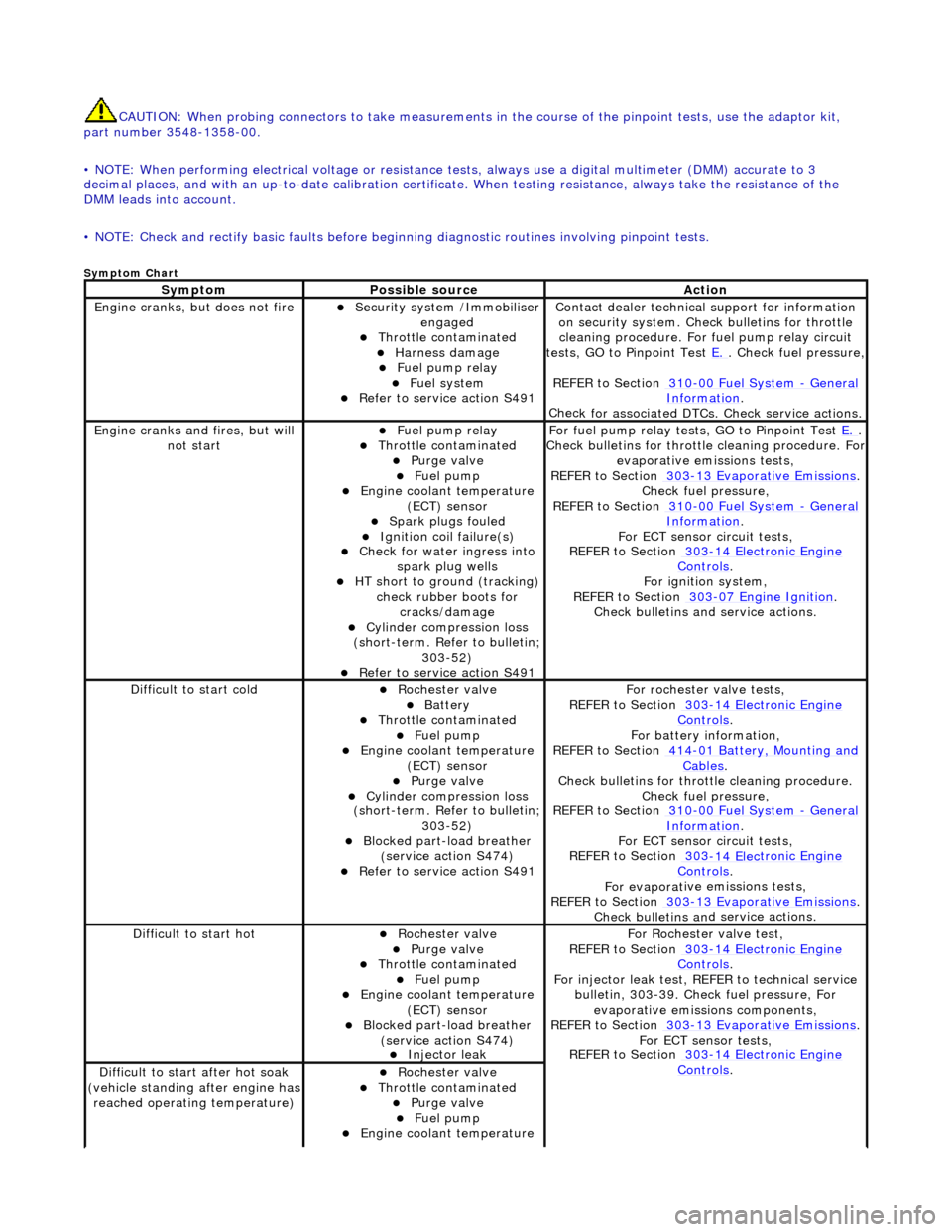
CAUTI
ON: When probing connectors to take
measurements in the course of the pinpoint tests, use the adaptor kit,
part number 3548-1358-00.
• NOTE: When performing electrical voltag e or resistance tests, always use a digital multimeter (DMM) accurate to 3
decimal places, and with an up-t o-date calibration certificate. When testing resistance, always take the resistance of the
DMM leads into account.
• NOTE: Check and rectify basic faults before beginning diagnostic ro utines involving pinpoint tests.
Sy
mptom Chart
Sy
mptom
Possib
le source
Acti
on
Engine
cranks, but does not fire
Secu
rity system /Immobiliser
engaged
Thr
ottle contaminated
Harness damage
F
uel pump relay
Fue
l system
R
efer to service action S491
Contact dealer techn
ical
support for information
on security system. Chec k bulletins for throttle
cleaning procedure. For fuel pump relay circuit
tests, GO to Pinpoint Test E.
.
Check fuel pressure,
REFER to Section 310
-00
Fuel System
- Gen
eral
Informati
on
.
Chec
k for associated DTCs
. Check service actions.
Engine
cranks and fires, but will
not start
F
uel pump relay
Thr
ottle contaminated
Purge
valve
Fue
l pump
Engine coolan
t temperature
(ECT) sensor
Spark plugs
fouled
Ignition coil
failure(s)
Check f
or water ingress into
spark plug wells
HT sho
rt to ground (tracking)
check rubber boots for cracks/damage
Cyl
inder compression loss
(short-term. Refer to bulletin;
303-52)
R
efer to service action S491
F
or fuel pump relay tests,
GO to Pinpoint Test E.
.
Check bull
etins for throttle cleaning procedure. For
evaporative emissions tests,
REFER to Section 303
-1
3 Evaporative Emissions
. Chec
k fuel pressure,
REFER to Section 310
-00
Fuel System
- Ge
neral
Informati
on
.
F
or ECT sensor circuit tests,
REFER to Section 303
-14 Elec
tronic Engine
Controls.
For ign
ition system,
REFER to Section 303
-07
Engine Ignition
.
Check bulletins an d service
actions.
D
ifficult to start cold
Roc
hester valve
Batt
ery
Thr
ottle contaminated
Fue
l pump
Engine coolan
t temperature
(ECT) sensor
Purge
valve
Cyl
inder compression loss
(short-term. Refer to bulletin;
303-52)
Blocked part-load breather (
service action S474)
R
efer to service action S491
F
or rochester valve tests,
REFER to Section 303
-14 Elec
tronic Engine
Controls.
F
or battery information,
REFER to Section 414
-0
1 Battery, Mounting and
Cables.
Check bull
etins for throttle cleaning procedure.
Check fuel pressure,
REFER to Section 310
-00
Fuel System
- Ge
neral
Informati
on
.
F
or ECT sensor circuit tests,
REFER to Section 303
-14 Elec
tronic Engine
Controls.
For evaporat
ive emissions tests,
REFER to Section 303
-1
3 Evaporative Emissions
. Check bulletins an
d
service actions.
D
ifficult to start hot
Roc
hester valve
Purge
valve
Thr
ottle contaminated
Fue
l pump
Engine coolan
t temperature
(ECT) sensor
Blocked part-load breather (
service action S474)
Injec
tor leak
F
or Rochester
valve test,
REFER to Section 303
-14 Elec
tronic Engine
Controls.
Fo
r injector leak test, REFER to technical service
bulletin, 303-39. Check fuel pressure, For evaporative emissions components,
REFER to Section 303
-1
3 Evaporative Emissions
. F
or ECT sensor tests,
REFER to Section 303
-14 Elec
tronic Engine
Controls. D
ifficult to start after hot soak
(vehicle standing after engine has
reached operating temperature)
Roc
hester valve
Thr
ottle contaminated
Purge
valve
Fue
l pump
Engine coolan
t temperature
Page 1022 of 2490
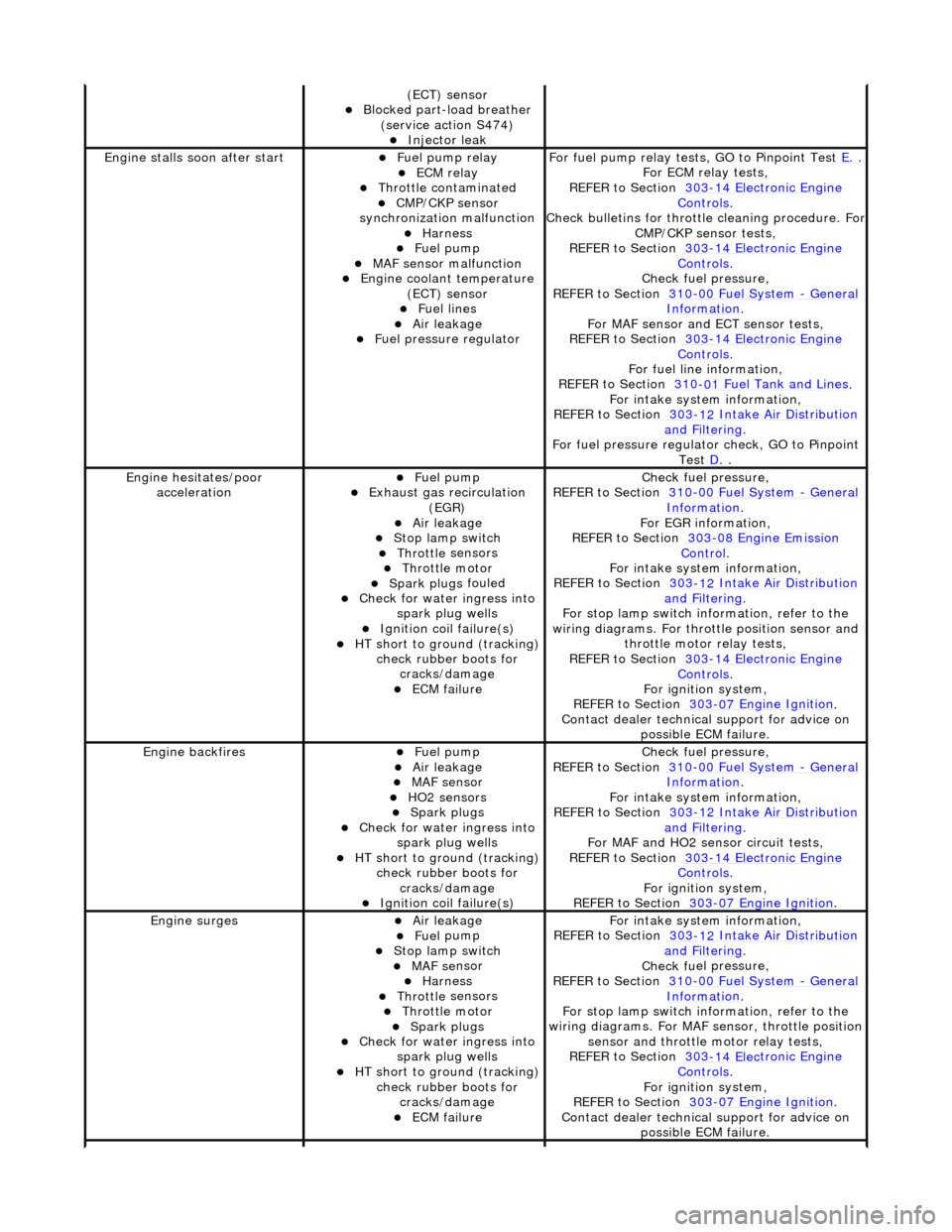
(ECT) se
nsor
Blocked part-load breather
(s
ervice action S474)
Injec
t
or leak
Engine stalls
soon
after start
F
u
el pump relay
ECM relay Thr
o
ttle contaminated
CMP/CKP sen
s
or
synchronization malfunction
Harness Fuel
pump
MAF
s
ensor malfunction
Engine coolan
t
temperature
(ECT) sensor
Fue l
lines
Air leakage Fu
el pressure regulator
F
o
r fuel pump relay tests,
GO to Pinpoint Test E.
.
F or ECM
relay tests,
REFER to Section 303
-14 Elec tronic En
gine
Controls.
Check bull etins for throttl
e cleaning procedure. For
CMP/CKP sensor tests,
REFER to Section 303
-14 Elec tronic En
gine
Controls.
Chec k fu
el pressure,
REFER to Section 310
-00 Fu
el System
- Ge
n
eral
Informati
o
n
.
F or MAF sensor and
ECT sensor tests,
REFER to Section 303
-14 Electronic En
gine
Controls.
For fuel l
ine information,
REFER to Section 310
-01
Fuel Tank and Lines
.
F or i
ntake system information,
REFER to Section 303
-1 2
Intake Air Distribution
and F
ilt
ering
.
F o
r fuel pressure regulato
r check, GO to Pinpoint
Test D.
.
Engine h e
sitates/poor
acceleration
Fue l
pump
Exhaus
t gas
recirculation
(EGR)
Air leakage Stop lamp swi t
ch
Throttl
e
sensors
Throttl
e
motor
Spark plugs
fouled
Check f
o
r water ingress into
spark plug wells
Ignition coil fail
ure(s)
HT sho
rt to ground (tracking)
check rubber
boots for
cracks/damage
ECM failu r
e
Chec
k fu
el pressure,
REFER to Section 310
-00 Fu
el System
- Ge
n
eral
Informati
o
n
.
F o
r EGR information,
REFER to Section 303
-08 En gin
e Emission
Control.
F or i
ntake system information,
REFER to Section 303
-1 2
Intake Air Distribution
and F
ilt
ering
.
F or stop l
amp switch in
formation, refer to the
wiring diagrams. For throttle position sensor and throttle motor relay tests,
REFER to Section 303
-14 Elec tronic En
gine
Controls.
For ign i
tion system,
REFER to Section 303
-07 En
gine Ignition
.
Contact dealer techn i
cal
support for advice on
possible ECM failure.
Engine ba ckfiresFuel
pump
Air leakage MAF s
e
nsor
HO2 sensors Spark plugs
Check fo
r water ingress into
spark plug wells
HT short to ground (tracking) check rubber
boots for
cracks/damage
Ignition coil fail
ure(s)
Chec
k fu
el pressure,
REFER to Section 310
-00 Fu
el System
- Ge
n
eral
Informati
o
n
.
F or i
ntake system information,
REFER to Section 303
-1 2
Intake Air Distribution
and F
ilt
ering
.
For MAF and HO2
sensor circuit tests,
REFER to Section 303
-14 Electronic En
gine
Controls.
For igni
tion system,
REFER to Section 303
-07 En
gine Ignition
.
Engine
s
urges
Air leakage Fue
l
pump
Stop lamp swi
t
ch
MAF s
e
nsor
Harness Throttl
e
sensors
Throttl
e
motor
Spark plugs
Check fo
r water ingress into
spark plug wells
HT sho rt to ground (tracking)
check rubber
boots for
cracks/damage
ECM failu r
e
F
or i
ntake system information,
REFER to Section 303
-1 2
Intake Air Distribution
and F
ilt
ering
.
Chec k fu
el pressure,
REFER to Section 310
-00 Fu
el System
- Gen
e
ral
Informati
o
n
.
F or stop l
amp switch in
formation, refer to the
wiring diagrams. For MAF se nsor, throttle position
sensor and throttle motor relay tests,
REFER to Section 303
-14 Elec tronic En
gine
Controls.
For ign i
tion system,
REFER to Section 303
-07 En
gine Ignition
.
Contact dealer techn i
cal
support for advice on
possible ECM failure.
Page 1023 of 2490
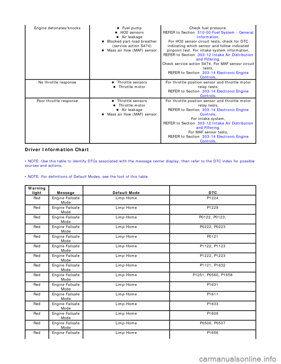
Driver Informa
tion Chart
•
NOTE: Use this table to identify DTCs associated with the me
ssage center display, then refer to the DTC index for possible
sources and actions.
• NOTE: For definitions of Default Modes, see the foot of this table.
Engine deton
ates/knocks
Fue
l pump
HO2 sensors Air leakage Blocked part-load breather
(
service action S474)
Mass ai
r flow (MAF) sensor
Chec
k fuel pressure.
REFER to Section 310
-00
Fuel System
- Gen
eral
Informati
on
.
F
or HO2 sensor circuit
tests, check for DTC
indicating which sensor and follow indicated
pinpoint test. For intake system information,
REFER to Section 303
-1
2 Intake Air Distribution
and F
iltering
.
Check service
action S474. For MAF sensor circuit
tests,
REFER to Section 303
-14 Elec
tronic Engine
Controls.
No
throttle response
Throttl
e sensors
Throttl
e motor
F
or throttle position se
nsor and throttle motor
relay tests,
REFER to Section 303
-14 Elec
tronic Engine
Controls.
Poor throttle responseThrottl
e sensors
Throttl
e motor
Air leakage Mass ai
r flow (MAF) sensor
F
or throttle position se
nsor and throttle motor
relay tests,
REFER to Section 303
-14 Elec
tronic Engine
Controls.
Fo
r intake system,
REFER to Section 303
-1
2 Intake Air Distribution
and F
iltering
.
For MAF
sensor tests,
REFER to Section 303
-14 Elec
tronic Engine
Controls.
Warning
lightMess
age
De
fault Mode
DT
C
Re
d
Engine
Failsafe
Mode
Lim
p-Home
P1224
Re
d
Engine
Failsafe
Mode
Lim
p-Home
P1229
Re
d
Engine
Failsafe
Mode
Lim
p-Home
P01
22, P0123,
Re
d
Engine
Failsafe
Mode
Lim
p-Home
P02
22, P0223
Re
d
Engine
Failsafe
Mode
Lim
p-Home
P0121
Re
d
Engine
Failsafe
Mode
Lim
p-Home
P11
22, P1123
Re
d
Engine
Failsafe
Mode
Lim
p-Home
P12
22, P1223
Re
d
Engine
Failsafe
Mode
Lim
p-Home
P11
21, P1632
Re
d
Engine
Failsafe
Mode
Lim
p-Home
P12
51, P0560, P1658
Re
d
Engine
Failsafe
Mode
Lim
p-Home
P1631
Re
d
Engine
Failsafe
Mode
Lim
p-Home
P1611
Re
d
Engine
Failsafe
Mode
Lim
p-Home
P1633
Re
d
Engine
Failsafe
Mode
Lim
p-Home
P1609
Re
d
Engine
Failsafe
Mode
Lim
p-Home
P05
06, P0507
Re
d
Engine
Failsafe
Lim
p-Home
P1656