1998 JAGUAR X308 Air Vent Cover
[x] Cancel search: Air Vent CoverPage 1768 of 2490
Climate Control System - General Infor
mation - Refrigerant System Tests
Gen
e
ral Procedures
WARNING: USE EXTREME CARE AND OBSERVE ALL SAFETY PRECAUTIONS RELATED TO THE USE OF REFRIGERANTS.
FAILURE TO FOLLOW THIS INSTRUCTION MAY RESULT IN PERSONAL INJURY.
CAUTION: The A/C refrigerant analyzer mu st be used before the recovery of any vehicle' s A/C refrigerant. Failure to
do so puts workshop bulk refrigerant at risk of contamination. If the vehicle A/C refrigerant is contaminated, refer the
customer to return to the repair facility that carried out the last A/C repair. If the customer wishes to pay the additional
cost, use the A/C recovery equipment that is designated for recovering contaminated A/C refrige rant. All contaminated A/C
refrigerant must be disposed of as hazardous waste. To prevent possible pe rsonal injury, for all equipment, follow the
equipment manufacturer's procedures and instructions.
• NOTE: Jaguar Cars Ltd. supports the effi cient usage, recovery and recycling of the refrigera nt used in passenger car air
conditioners. Jaguar Cars Ltd. recommend s the use of UL-approved recovery/recycling equipment during any A/C system
repair and recharge procedure which requ ires that the system be evacuated.
1. Us
e UL-approved recovery/recycling equipment to evacuate
and recover the A/C system.
Follow t h
e equipment manufacturer's procedures and
instructions for use of equipment.
Page 1777 of 2490
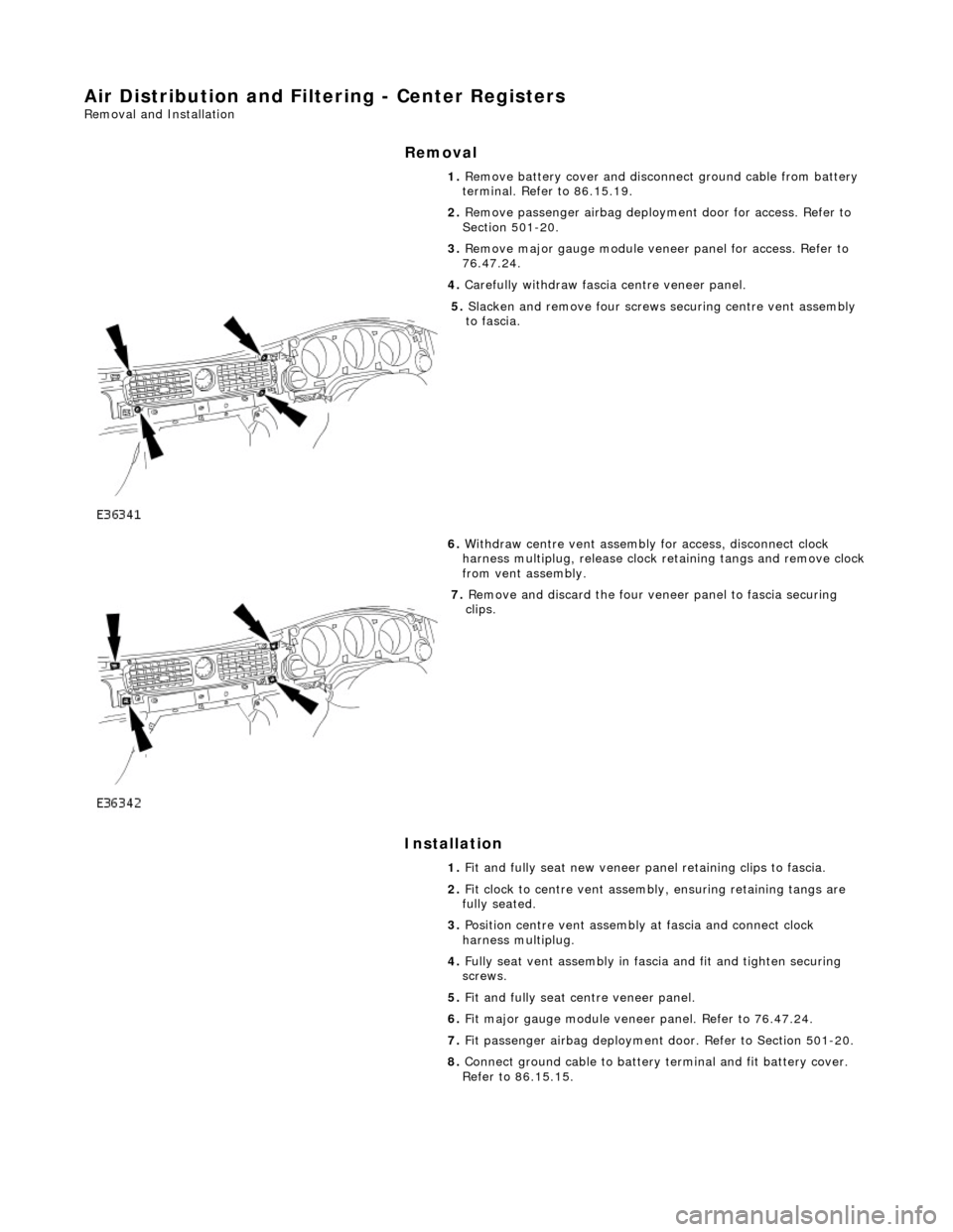
Air Distribution and Filtering - Center Registers
Removal and Installation
Removal
Installation
1.
Remove battery cover and disconnect ground cable from battery
terminal. Refer to 86.15.19.
2. Remove passenger airbag deployment door for access. Refer to
Section 501-20.
3. Remove major gauge module veneer panel for access. Refer to
76.47.24.
4. Carefully withdraw fascia centre veneer panel.
5. Slacken and remove four screws securing centre vent assembly
to fascia.
6. Withdraw centre vent assembly for access, disconnect clock
harness multiplug, release clock retaining tangs and remove clock
from vent assembly.
7. Remove and discard the four veneer panel to fascia securing
clips.
1. Fit and fully seat new veneer panel retaining clips to fascia.
2. Fit clock to centre vent assemb ly, ensuring retaining tangs are
fully seated.
3. Position centre vent assembly at fascia and connect clock
harness multiplug.
4. Fully seat vent assembly in fascia and fit and tighten securing
screws.
5. Fit and fully seat centre veneer panel.
6. Fit major gauge module veneer panel. Refer to 76.47.24.
7. Fit passenger airbag deployment door. Refer to Section 501-20.
8. Connect ground cable to battery terminal and fit battery cover.
Refer to 86.15.15.
Page 1788 of 2490
Heating and Ventilation - Heater Core and Evaporator Core Housing
Removal and Installation
Removal
1. Disconnect battery ground cable (IMPORTANT, see SRO
86.15.19 for further information).
2. Recover refrigerant from air co nditioning system; refer to
82.30.30.
3. Drain radiator coolant only; refer to 26.10.01 or (SC)
26.10.01.
4. Remove instrument panel for access, refer to 76.46.01.
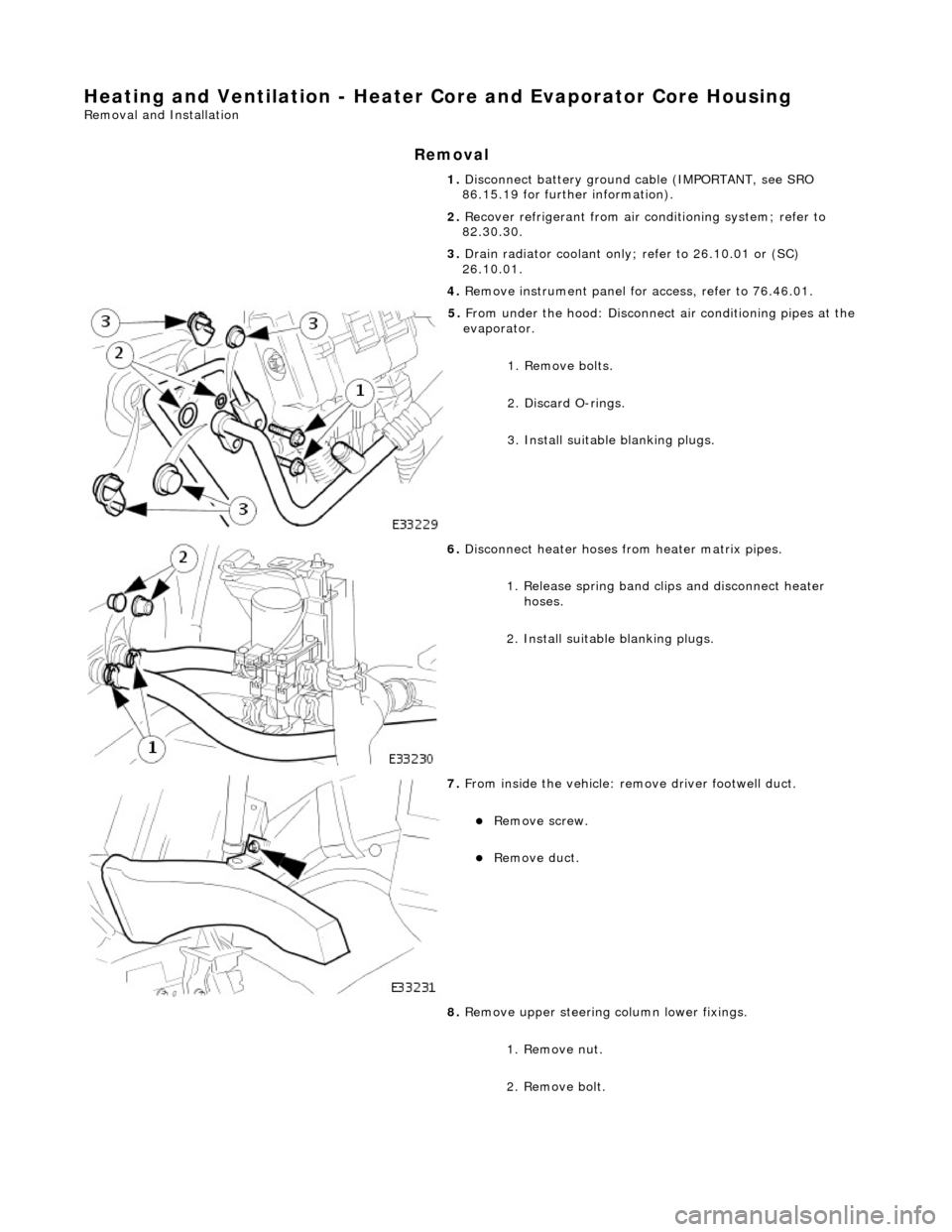
5. From under the hood: Disconnect air conditioning pipes at the
evaporator.
1. Remove bolts.
2. Discard O-rings.
3. Install suitable blanking plugs.
6. Disconnect heater hoses from heater matrix pipes.
1. Release spring band clips and disconnect heater hoses.
2. Install suitable blanking plugs.
7. From inside the vehicle: re move driver footwell duct.
Remove screw.
Remove duct.
8. Remove upper steering column lower fixings.
1. Remove nut.
2. Remove bolt.
Page 2002 of 2490
Repair Procedure
• CAUTIONS: Do not use crimping pliers, insulation strippers, butt splice connectors, heat sh rink sleeves or pre-terminated wiring
harness(s) that are not supplied with the Jagu ar wiring harness repair kit. Each part has been designed to be used only with
the other parts in this wiri ng harness repair kit.
Where the repair procedure indicates that a glue lined heat shrink sleeve should be applied, apply sufficient heat to
the glue lined heat shrink to melt the glue in order to provide a water tight seal. Do not
over heat the glue lined heat shrink sleeve so that the wiring harness insulation becomes damaged.
It is not correct to make more than five repair joints on the wiring harness to any electrical connector and if more damage is
found at the same electrical connector then a new wiring harness must be installed.
Remove the faulty terminal from the elec trical connector using the extractor tool and correct tip. Make sure that any
anti-backout device is released befo re trying to remove the terminal.
CAUTION: : A number of electrical connector terminals ar e gold plated or gold flashed. When defective, they
must be installed with a gold pre-terminated wiring harnes s(s) from the wiring harness repair kit. It is not always
easy to identify the female as gold but the male pins are visually easier, therefore always check both male and
female terminals to identify those which are gold. Under no circumstances are gold and tin terminals to be mixed as
this will lead to early failur e of the electrical contact.
• NOTE: Never use a harness lead with a smalle r diameter than the original harness lead.
Select the correct size and ty pe of pre-terminated wiring harness and butt splice connector from the wiring harness
repair kit.
Using the wire cutter on the stripping tool, cut the pre-terminated wiring harness and the harness cable to the
required length.
• NOTE: See illustration: Stripping Insulation
From the Relationship Table, find the correct length of insulation to be stripped from the pre-terminated wiring
harness and set the adjustable cable length stop to the correct length. Place the pre-terminated wiring harness in
the wire stripper and remove the insulation.
Put the cable identification sleeve(s) on to the wiring harness with the main cable colour nearest to the terminal. During this next step do not overtighten. Place the selected butt splice connector in the crimping tool, matching the
aperture and the butt connector colours. Make sure that the window indentation in the butt connector is resting over
the guide bar on the lower jaw. Partially close the grip until the butt connec tor is securely held in the aperture. This
will give support to the butt conn ector while the pre-terminated wiring harness is inserted into it.
• NOTE: See illustration: Spice Correctly Located
Insert the pre-terminated wiring harnes s into the butt connector and make sure that the wire is against the wire
stop. Close the grip firmly, crimping the lead to the butt connector. When the handles have been completely closed
the butt connector will be fre ed from the tool as the handles are released. If the handles have not been completely
closed then the jaws will hold the butt connector and it cannot be removed from the tool until the crimp is fully made
by closing the handles completely. Make sure that the harness cable has been squarely cut and the correct length of insulation removed. If more than
one splice is needed the butt connectors must be not be crimped to the wiring harness at the same distance from
the connector. The splices must be staggered to prevent a bulk of splices in the same area of the wiring harness.
It is preferable to cover the butt splice joint with heat shrink sleeve. This is desirable not essential, except where the
electrical connector is a sealed electrical connector. Use the smaller diameter sleeve for red and blue pre-terminated
wiring harness(s) and the large diameter sleeve for the yellow pre-terminated wiring harnes s(s). It is advisable to
place the heat shrink over the completed joint but in some instances the sleeve will not pass over the terminal.
Check, and if required, place the correct size sleeve onto the harness cable or pre-terminated wiring harness before
crimping the butt splice to the wiring harness.
Place the harness cable into the butt splice with the spli ce window over the guide bar. Make sure that the cable
harness wire is agains t the stop in the butt splice, crimp the butt splice connector to the wiring harness.
Gently pull the harness cables each side of the butt sp lice to make sure that a secure joint has been made.
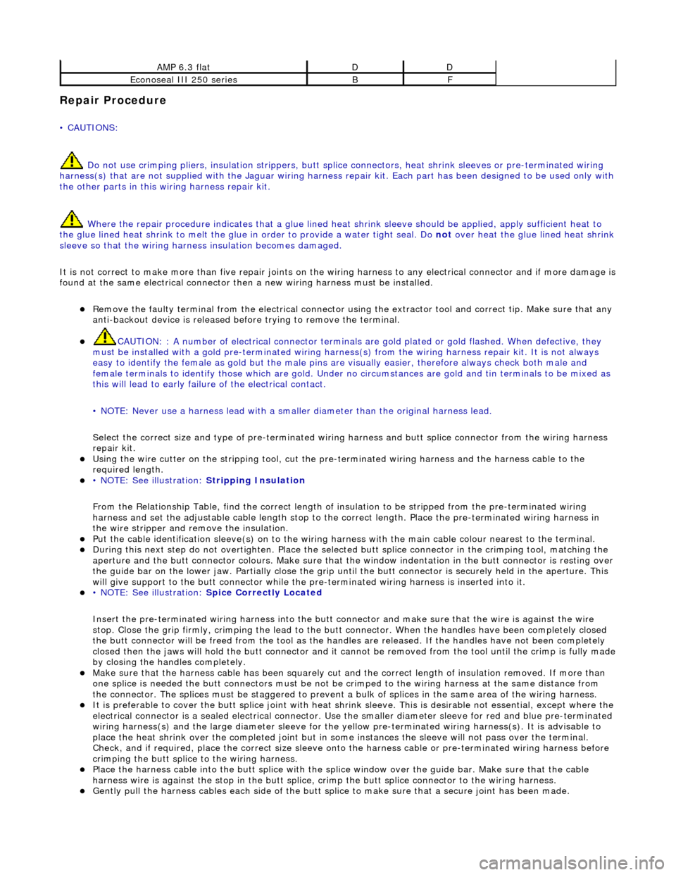
AMP 6.3 flatDD
Econoseal III 250 seriesBF
Page 2023 of 2490
sliding roof finisher and clips. Carpet covered trims line the trunk and are secured by fir tree fasteners to the sides and fro nt inner panel.
Rear View Mirrors
The.interior rear view mirror is an electrochromic unit that automatically da rkens to prevent glare from following vehicle
lights. This automatic function is selected by pressing the switch at the bottom of the mirror. Pressing the switch again
cancels this function. An LED then illuminates when automatic dipping is operative. The light sensing unit for the Night
Sentinel automatic lamp operating system is also incorporated in the mirror casing.
The door mirrors are cheater mounted, colo r-keyed units, remote electrically adjustable and heated. Adjustment of both
mirrors is carried out from the driver's door switchpack.A slider switch selects the mirror to be adjusted, and a disc switch
adjusts the selected mirror to the required position. Mirror ad justment can only be made when the ignition switch is in
position I or II or the driver's door is open, and the selector switch is moved from the central position. The door mirrors also
automatically darken under control of the electrochromic interior rear view mirror. Mirror heating elements operate on
selection of backlight heating.
Automatic dipping of passenger door mirror for kerb view when reversing, is fitted as part of the memory pack. With the
ignition switch in position II, the mirror selector switch in the left or right position and reverse gear selected, automatic
dipping is initiated by moving the mirror toggle switch rearwards and releasing. On receipt of the dip signal, the passenger
door mirror is driven downwards either 7 degrees, bottom of travel, or 4,5 to 5,5 seconds, whichever occurs first.
Subsequent rearward movement of the toggle switch achieves further dipping of the mirror in the same increments and
sequence. The mirror can be manu ally returned to the normal memorised positi on by moving the toggle switch forward with
reverse gear selected. The mirror will auto matically return to memorised position on deselection of reverse gear, or moving
ignition switch from position II.
Door mirror fold-back where fitted, to facilitate parking in conf ined spaces, can be initiated when the ignition switch is in
position I or II, the mirror selector switch is in the centra l position and vehicle speed is below 19 km/h (12 mph). Mirror
fold-back is then initiated by moving the toggle switch rear wards and releasing it. The door mirrors are returned to the
normal driving position by agai n moving toggle switch rearwards. There is no speed constraint on this operation. In the
event of a fold-back mirror becoming 'out of position' due to acci dental impact, it must only be re-positioned by initiating
the fold-back sequence.
Loss of power supplies will result in loss of mirror fold-back memory. In the event of such a memory loss with mirrors in the
normal position, fold-back will operate on second movement of the toggle swit ch. On loss of memory with mirrors in the
fold-back position, they will return to the no rmal position on next fold-back operation.
Bumpers
Each bumper comprises a beam mounted to the body via two strut assemblies, and a moulded polypropylene cover
incorporating side armatures and chrome plated blades. Each strut is secured to the BIW by three bolts and supports the
beam on a single bolt/height adjuster. The front bumper cover which is moulded to form a lo wer air intake for the cooling
pack, also incorporates left and right handed twin fog lamps, brake coolin g ducts. Side marker lamps fitted for some
markets serve only as reflectors for UK and Europe. A plastic undertray secured to the lower edge of the front bumper,
improves airflow and minimises the ingres s of road grime in that area. Standard bumpers have glass mat thermoplastic
(GMT) beams mounted on GMT struts. For certain markets, aluminium bumper beams are installed on menasco energy
absorbing struts. Whilst both types of front bumper provide a fu lly integrated 'soft front end' that satisfies bumper impact
requirements, the energy absorbing front and rear bumpers are further designed to withstand 5mph (8kph) impacts with no
visible damage sustained. Side markers/re flectors, and direction indicators are designed for ease of ac cess from the outside
of the bumper. For adjustment and bulb change, the fog lamps are accessed from th e bumper interior. The bumper covers
are body coloured and matched. Replacement covers are supplied complete with side armatures and are finished in primer
Trunk
The trunk houses the spare wheel, the battery, an electrical carrier containing electrical fuses, relays and modules and a
compact disc auto-changer attached to body bracketry. The trun k is fitted with push-fit liners to the sides and front inner
panel.The carpet covered floor is in two removable sections, one covering the spare wheel and wheel changing equipment,
the other covering the battery and electrical carrier. The front and rear edges of the floor board loca te in blocks on the fuel
tank backboard and the rear of the body , which provide two height settings to accommodate the difference in thickness
between the space saver and full sized spare wheels. A moulded finisher covering the rear of the trunk below the sill is
secured to the rear panel by tabs and fir tree fasteners. Finisher panels fitted over the rear lamp units provide for access
from the trunk. Finisher panels fitted to the rear lamp units provide trunk inte rior access to the lamps. The trunk lid
underside is fitted with a removable mo ulded liner and two trunk illumination light s. Trunk locking is based on a central
latch and striker, operated electrically through the central lo cking system by an adjacent actuator or by key in a barrel lock
Page 2024 of 2490
located behind the trunk lid badge.
Occupant Restraints
Inertia reel seat belts with electronically controlled pre-tensioners are installed at the front seats. Supplementary occupant
restraint is provided for driver and front seat passenger by front airbags, and side air bags installed in the outer wing of
each front seat. Standard inertia reel type belts are fitted to all three rear seat positions. The front seat belts are provide d
with height adjuster units which are attached one to each of the 'B' posts. Where emergency locking retractor/automatic
locking retractor seat belts are provided, the belts have two operating modes.The inertia reel mode with emergency locking
retractor is for adult passenge r use only and operates to allow the occupant some freedom of tors o movement under normal
travel conditions.. The static reel mode which prevents belt payout and must be used when a ch ild seat is installed, is
activated by fully extending the belt to engage the ratchet me chanism,.then releasing the belt. Operation of the ratchet will
then be felt and the belt w ill become locked in that position. To revert to in ertia reel (adult passenger) mode, pay the belt
back into the reel to th e fully retracted position.
Body Structure
The XJ8 sedan body is produced in monocoque standard and lo ng wheelbase form. 70% of the body panels are zinc coated
to achieve optimum corrosion protection and a further 8% are constructed in high st rength steels to provide high torsional
strength and passenger impact protection.
Doors
Each front and rear door consists of a we lded, mild steel inner frame and an outer panel. The outer panel is welded to the
waist rail and cheater of the inner frame, then bonded and clinched to fo rm the door assembly. Cosmetic PVC bead is
applied to all clinch joints
Hood
The hood consists of one piece inner an d outer panels clinched and bonded toge ther, with cosmetic bead PVC sealant
applied to all clinch joints. The hood pivo ts at the front on two hinges each secured by bolts to the hood front underside and
the BIW front upper crossmember. Two gas struts secured to the hood by pi vot pins and snap-on couplings, support the
hood in the open position.
Trunk
The trunk lid is of similar construction to the hood, consisting of inner and outer panels clinched and bonded together and
PVC bead sealed. The trunk accommodates the spare wheel, the battery, an electrical carrier containing electrical fuses,
relays and modules and where premium ICE is fitted, a compac t disc auto-changer mounted on body bracketry. Carpet
covered trims line the trunk sides and front inner panel and a po lyurethane rear finisher is secured to the rear panel by
spring clips and fir tree fasteners.
B and C Post Reinforcement
Page 2038 of 2490
Body Closures - Door
Removal and Installation
Removal
Installation
WARNING: FOLLOWING REPAIR OR RENEWAL OF A FRONT DOOR, IT MUST BE ENSURED THAT A SIDE AIRBAG
WARNING LABEL IS AFFIXED TO THE REAR FACE OF THE DOOR.
• NOTE: The hinges are set during manufacture to achieve correct door fitment. This setting should on ly require adjustment
in the event of damage at the body or door hinge locations. 1.
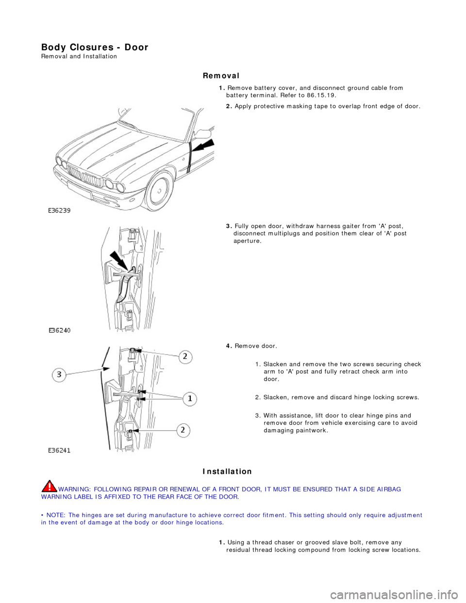
Remove battery cover, and di sconnect ground cable from
battery terminal. Refer to 86.15.19.
2. Apply protective masking tape to overlap front edge of door.
3. Fully open door, withdraw harness gaiter from 'A' post,
disconnect multiplugs and posi tion them clear of 'A' post
aperture.
4. Remove door.
1. Slacken and remove the two screws securing check
arm to 'A' post and fully retract check arm into
door.
2. Slacken, remove and di scard hinge locking screws.
3. With assistance, lift d oor to clear hinge pins and
remove door from vehicle exercising care to avoid
damaging paintwork.
1. Using a thread chaser or gr ooved slave bolt, remove any
residual thread locking compound from locking screw locations.
Page 2054 of 2490
Interior Trim and Ornamentation - Interior Trim
Description and Operation
Carpets
The passenger compartment carpet is a one piece moulded constr uction with integral sound deadening material, heel mats
and driver's footrest. The carpet is attach ed to the vehicle floor by plastic clips fitted below the door treadplates. Removal of the carpet necessitates re moval of the front seats, lifting of the centre console rear extens ion and removal of the heelboard
carpet.
Fascia
The full width, slush moulded, soft feel PVC fascia is mounted on an injection moulded armature and is faced with wood
veneer. In addition to the air conditioning and central, outer and demisting vents, it accepts instrument packs dedicated to
market requirements and a centrally mounted analogue clock.
Doors
The one-piece door casings are trimmed in UEV to match the seating, with wood veneer at the waistline and a carpet insert
at the front lower corner. Each casing is secured to the door inner panel by fir tree press fast eners along the lower section,
two armrest fixings at the centre and vene er panel dowels and fixings at the top. The armrests which are common to front
and rear doors, are trimmed in matching leather or UEV according to specification. The door switchpacks, dedicated to
driver and front or rear passenger, are in corporated in the armrests. A speaker is in stalled in the lower section of each door
and a tweeter is incorporated behind each interior door handle escutcheon. Where premium ICE is fitted, the front tweeters
are installed in the upper A posts.
A, B, C and D Posts
On each side,a grained UEV finisher trimmed to match the headlining is secured to the 'A' post and cantrail by fir tree
fasteners locating in BIW apertures. The upper 'D' post finisher is trimmed and secured in the same manner. The single
piece'B/C' post finishers, also finished in grained matching UEV, each have a front se at belt exit aperture and are secured to
the BIW by four spring clips and two fir tree fasteners.
Headlining
The one-piece headlining consists of a 6mm thick polyurethane foam membrane covered with suede effect knitted polyester. The headlining is secured to the BIW roof by body tangs, the roof console, sun visors, combined grab handles and coat
hooks, the cantrail finishers and where fitt ed, the sliding roof finisher and clips.
Trunk
Carpet covered trims line the trunk and are secured by fir tr ee fasteners to the sides and front inner panel. The carpet
covered, two-section, removable trunk fl oor provides access to the spare wheel and wheel changing equipment, the battery
and electrical carrier. The floor board rests on the spare wheel, with the front and rear edges locating in blocks on the fuel
tank backboard and the rear of the body. The support blocks provide for two floor he ight settings to accommodate either a
space saver or full size spare wheel.A moulded finisher covering the rear of the trunk below the sill is secured to the rear
panel by tabs and fir tree fasteners. Finish er panels fitted to the rear lamp units provide trunk interior access to the lamps.
The trunk lid underside is fitted with a removabl e moulded liner and two trunk illumination lights.